14
10-V1011
Z3200
Z3200
10-V1011
15
–
English
–
Deutsch
–
English
–
Deutsch
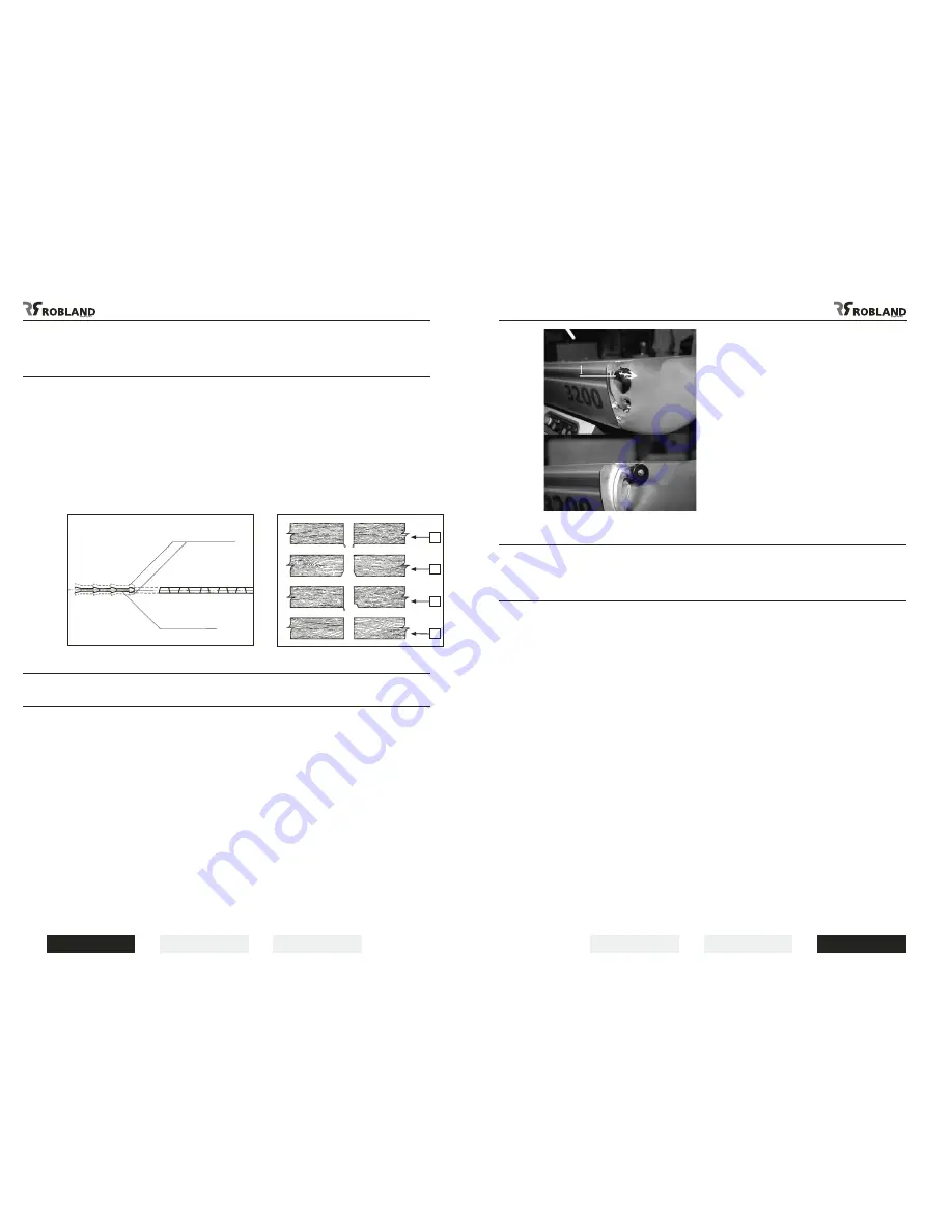
Lateral adjustment
of the scoring blade
(Fig.13-14)
Each time the main sawblade is replaced by a new one, or even a newly sharpened sawblade, the
scorer has to be adjusted to match the main sawblade teeth width. It is very important that this is done
in the correct way to ensure a clean cut, free of splintering.
The use of two piece scoring saws is best because they can easily be adjusted using spacer rings.
The lateral movement of the scorer sawblade is achieved by turning the knob (fig. 11,5) and the locking
(fig. 11,6).
After the lateral adjustment is done the scale (fig. 11,7) has to be set at “0”.
Figures 13 and 14 show the different possibilities :
1) Without the use of a scorer saw
2) Correct setting of the scorer saw but too deep
3) Too much to the right side
4) Correct setting of the scorer saw.
Blocking the sliding table
(Fig.15)
Blocking the sliding table (Fig.14)
-
The sliding table can be blocked in two positions and with one block-system. This is vital for
example by loading of the boards or cutting along the parallel guide. The system is located on the
front-side of the sliding table. Pull the button (1) in your direction and turn to the right to liberate the
table. Pull the sliding table till end, the table will be blocked automatically when arriving in the exact
position. Continue this way to start working.
-
When several movements are repeated consecutively, it is possible that the bearing cage between
the two profiles moves a little bit. We can note this as well by a reducing travelling distance of the
sliding table. To proceed and achieve the normal travelling distance of the sliding table, you can
adapt the position of the bearing cage: simply push the table with a few short, light pushes against
the buffer stop at the end of the sliding table until the position of the ball carrier is adjusted and the
table can be moved again along its full stroke.
Attention: cleaning and maintenance of the sliding table
It is vital to regularly blow away the saw- and other dust, collected between the sliding table
and the bearing cage. Push the sliding table to the end, to get a better reach towards the rails,
the bearing cage and gliding tracks. Oil serves to lubricate the sliding rails and is an extra
guarantee of good use and function.
Maintenance and lubrication
of the sliding table
It is highly recommended to clean the sliding table once a week, and to remove all sawdust and chips
which gradually slow down the sliding table. From both sides of the sliding table blow out the dust
accumulated between the two sections and on the ball carrier.
This can be done more easily and efficiently when the upper part of the sliding table is slid to the rear,
and must then be repeated with the upper part at the front end.
After all dust has been blown out, a thin oil with a teflon base or plain diesel oil should be sprayed onto
the steel V-liner strips on both the upper and lower part of the sliding table. Never use a thick oil or
grease ! This maintenance job will only take 10 minutes of your time, and will ensure the
machine gives full satisfaction.
1
2
3
4
NOT CORRECT
CORRECT
Fig.13
Fig.15
Fig.14


