background image

- 2 -

ASSEMBLY

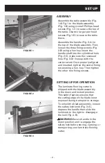
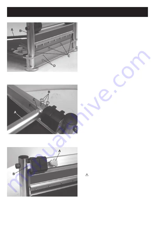
Assemble the table assembly (Fig. 

1-A) Fig.1 to the blade assembly 

(Fig. 1-B) using 4 small Phillips head 

screws (Fig. 1-C) to secure the top of 

the table. Use two larger pan head 

screws (Fig.1-D) to secure the table 

brace.
Assemble the handle (Fig. 2-A) to 

the top of the blade assembly. First, 

loosen the three fixing screws (Fig. 

2-B) using a hex key. Insert the 

handle shaft into the cylindrical hole 

(Fig. 2-C), make sure the recessed 

hole (Fig. 3-D) lines up with the 

center screw. Once properly aligned 

and inserted, tighten the center fixing 

screw using a hex. key. Then tighten 

the other two fixing screws. 

SETTING UP FOR OPERATION

The laminate flooring cutter is 

shipped with the blade assembly 

in the down and locked position. 

This safety feature ensures that 

the cutting edge of the blade is not 

exposed during transport or storage. 

To unlock the blade assembly, loosen 

the safety lock knob (Fig. 3-A), 

depress the handle then slide the 

lock knob to the right to disengage 

the lock (Fig. 3-B).
    WARNING Secure handle in the 

down position and re-engage the 

safety lock before storing, carrying or 

transporting your laminate flooring 

cutter.

SET UP

FIGURE 1

FIGURE 2

FIGURE 3

Содержание 10-63

Страница 1: ...sult in serious bodily injury SAVE THESE INSTRUCTIONS FOR FUTURE REFERENCE AVERTISSEMENT Lire et comprendre toutes les directives Le non respect des directives peut causer des blessures graves VEUILLE...

Страница 2: ...secure Operate only on a firm substrate or solid stand 8 Use the right tool Do not force the 13 Multi Floor Cutter or use it for a job for which it was not designed use only on approved materials 9 Ke...

Страница 3: ...properly aligned and inserted tighten the center fixing screw using a hex key Then tighten the other two fixing screws SETTING UP FOR OPERATION The laminate flooring cutter is shipped with the blade a...

Страница 4: ...chment Fig 5 and hold the material with foot then push handle down to complete a cut WARNING Maintain control of the handle Do not allow handle to slam back after making cut 45 CUTTING Swing the angle...

Страница 5: ...w is 125mm The adjustment on both plates must be the same 3 Cut a piece of paper to ensure the tool is set correctly Fig 8 CUT GUIDE Your tool cuts a wide variety of products Please refer to this cut...

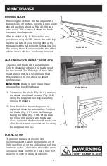
Страница 6: ...d that this operation be done by a qualified professional WARNING Blade is very sharp Wear gloves when handling blade 1 To remove the blade Fig 10 A remove the seven allen head screws Fig 10 B using t...

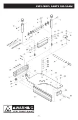
Страница 7: ...6 EXPLODED PARTS DIAGRAM...

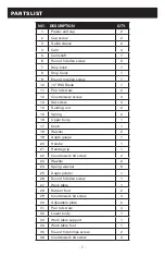
Страница 8: ...3 Set screw 4 14 Guiding rod 2 15 Spring 2 16 Upper body 1 17 Knob 1 18 Washer 2 19 Angle guage 1 20 Handle 1 21 Handle grip 1 22 Countersunk hd screw 2 23 Washer 2 24 Spring washer 8 25 Angle pointer...

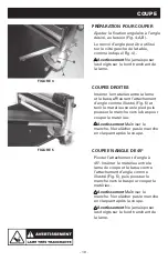
Страница 9: ...pas le Coupeuse planchers multiples de 330mm ou ne l utilisez pas pour une tache pour laquelle il n a pas t con u utilisez uniquement sur des mat riaux approuv s 9 Maintenir la lame aiguis e Une lame...

Страница 10: ...align et ins r serrez la vis de fixation du centre Finalement serrez les deux autres vis de fixation SETTING UP FOR OPERATION Le coupe de sol stratifi est exp di avec l ensemble de couteau abaiss et...

Страница 11: ...tenir le mat riau sous le pied puis pousser le manche vers le bas pour couper le mat riau Avertissement Ma triser le manche Ne rel cher pas le manche en claquant apr s la coupe COUPE EN ANGLE DE 45 Pi...

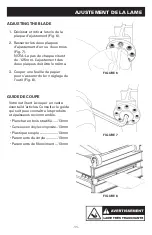
Страница 12: ...es deux plaques doit tre le m me 3 Couper une feuille de papier pour s assurer du bon r glage de l outil Fig 8 GUIDE DE COUPE Votre outil sert couper un vaste ventail d articles Consulter le guide qui...

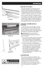
Страница 13: ...ualifi Avertissement Le couteau est tr s tranchant Avant de manipuler le couteau portez des gants 1 Pour retirer le couteau Fig 10 A d vissez et retirez les sept vis t te hexagonaux Fig 10 B en utilis...

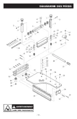
Страница 14: ...13 DIAGRAMME DES PI CES...

Страница 15: ...ns t te 4 14 Tige de guide 2 15 Ressort 2 16 Corps sup rieur 1 17 Bouton 1 18 Rondelle 2 19 Jauge d angle 1 20 Manche 1 21 Poign e du manche 1 22 Vis t te frais e 2 23 Rondelle 2 24 Rondelle ressort 8...

Страница 16: ...erficie firme o soporte solido 8 Use la herramienta adecuada No fuerce el Cortador para m ltiples pisos de 330mm o ni lo utilice para un trabajo para el cual no fue dise ado utilizar s lo en materiale...

Страница 17: ...do e insertado apropiadamente ajuste el tornillo fijador central utilizando una llave hexagonal Despu s ajuste los otros dos tornillos fijadores ALIST NDOLO PARA SU OPERACI N El cortador para pisos la...

Страница 18: ...a Fig 5 y mantenga el material con el pie y luego empuje la palanca hacia abajopara completar un corte Advertencia Mantenga el control de la palanca No permita que la palanca regrese despu s de hacer...

Страница 19: ...el mismo 3 Corte un pedazo de papel para asegurarse que la herramienta haya sido ensamblada correctamente Fig 8 GU A DE CORTE Su herramienta corta una gran variedad de productos Por favor refi rase a...

Страница 20: ...la realice alguien del personal especializado Advertencia La cuchilla es muy filuda Utilice guantes cuando se encuentre utilizando la cuchilla 1 Para remover la cuchilla Fig 10 A remueva los siete to...

Страница 21: ...20 DIAGRAMA DE LAS PARTES...

Страница 22: ...justar 4 14 Varilla gu a 2 15 Resorte 2 16 Cuerpo superior 1 17 Perno 1 18 Arandela 2 19 Calibrador del ngulo 1 20 Manija 1 21 Mango de la manija 1 22 Tornillo con cabeza avellanada 2 23 Arandela 2 24...

Страница 23: ...22 NOTES NOTES NOTAS...

Страница 24: ...www robertsconsolidated com Roberts Consolidated Industries Inc Boca Raton FL 33487 Made in China Fabriqu au Chine Hecho en China N2717 10718 CUSTOMER SERVICE 1 866 435 8665...

Отзывы: