UHD L
OW
P
ROFILE
D
UCT
F
URNACE
I
NSTALLATION
O
PERATION
AND
S
ERVICE
M
ANUAL
14 of 47
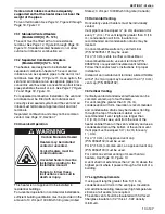
7.7.1 Maximum Vent Len
g
ths
7.
8
Vent Material
V
ent material may be single
w
all 26 ga. (minim
u
m)
galvanized steel or eq
u
al thickness stainless steel.
Completely seal all joints, refer to
Page 12, Section
7.3
.
If penetrating a comb
u
stible
w
all or roof, a listed
thimble
w
ith 2" (5 cm) clearance m
u
st be
u
sed.
Where local codes permit, a single section of type
B-1 vent material may be
u
sed at the roof or
w
all
penetration instead of a thimble. Ens
u
re vent
man
u
fact
u
rer's clearance from vent material is
maintained. Seal ann
u
lar space of the type B-1 vent
as
w
ell as all joints in the remaining vent.
7.9 Replacin
g
an Existin
g
Heater in a Ventin
g
System
When replacing an existing heater in a venting
system, the venting system may not be properly
sized to vent the ne
w
heater. The follo
w
ing steps
m
u
st be follo
w
ed
w
ith each appliance connected to
the venting system placed in operation,
w
hile any
other appliances connected to the venting system
are not in operation.
1. Seal any
u
n
u
sed openings in the venting
system.
2. Inspect the venting system for proper size and
horizontal pitch, as req
u
ired by the NFPA 54/
ANSI Z223.1 - latest revision, National F
u
el
Gas Code (US) or Standard CSA B149.1
Nat
u
ral Gas and Propane Installation Code
(Canada) and these instr
u
ctions. Determine
that there is no blockage or restriction, leakage,
corrosion and other deficiencies
w
hich co
u
ld
ca
u
se an
u
nsafe condition.
3. Close all b
u
ilding doors and
w
indo
w
s and all
doors bet
w
een the space in
w
hich the
appliance(s) connected to the venting system
are located and other spaces of the b
u
ilding.
T
u
rn on clothes dryers and any exha
u
st fans,
s
u
ch as range hoods and bathroom exha
u
sts
so that they shall operate at maxim
u
m speed.
Do not operate a s
u
mmer exha
u
st fan. Close
fireplace dampers.
4. Follo
w
the lighting instr
u
ctions. Place the
appliance being inspected in operation.
Adj
u
st thermostat so that the appliance
w
ill
operate contin
u
o
u
sly.
5. For any appliance having a draft hood, test for
draft hood appliance spillage at the draft hood
relief opening after five min
u
tes of main b
u
rner
operation. Use the flame of a match or candle.
6. After it has been determined that each
appliance connected to the venting system
properly vents
w
hen tested as o
u
tlined above,
ret
u
rn doors,
w
indo
w
s, exha
u
st fans, fireplace
dampers and any other gas-b
u
rning appliances
to their previo
u
s conditions of
u
se.
7. If improper venting is observed d
u
ring any of
the above tests, the venting system m
u
st be
corrected by a contractor q
u
alified in the
installation and service of gas-fired eq
u
ipment
or yo
u
r local gas s
u
pplier. If the venting m
u
st be
resized,
u
se appropriate tables in (US)
Appendix G of NFPA 54/ANSI Z223.1 - latest
revision, National F
u
el Gas Code (US) or
Standard CSA B149.1 Nat
u
ral Gas and
Propane Installation Code (Canada) to
determine minim
u
m size. All vent corrections
m
u
st be in accordance
w
ith the appropriate
local codes and the NFPA 54/ANSI Z223.1 -
latest revision, National F
u
el Gas Code (US) or
Standard CSA B149.1 Nat
u
ral Gas and
Propane Installation Code (Canada).
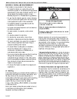
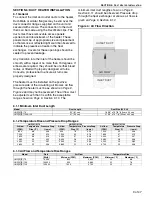
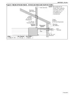
Fi
g
ure
8
: Vent and Roof Detail
Model UHD[X][S] 75, 100, 125
Number of Elbows
40 ft (12.2 m)
1
35 ft (10.7 m)
2
30 ft (9.1 m)
3
25 ft (7.6 m)
4
20 ft (6.1 m)
5
Содержание Combat UHDXS 100
Страница 2: ......
Страница 4: ......
Страница 6: ......
Страница 8: ......
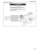
Страница 29: ...SECTION 9 GAS PIPING 21 of 47 Figure 14 Gas Connection ...
Страница 43: ...SECTION 14 TROUBLESHOOTING 35 of 47 14 1 General ...
Страница 54: ...UHD LOW PROFILE DUCT FURNACE INSTALLATION OPERATION AND SERVICE MANUAL 46 of 47 ...
Страница 56: ......
Страница 57: ......
Страница 58: ......
Страница 59: ......
Страница 60: ......


