background image

9

© 2019 Robern, Inc. 701 N. Wilson Ave. Bristol, PA  19007  U.S.A.

800.877.2376      

www.robern.com


Installation instructions 

Part no. 209-1311-rA   rev. 06/13/19

Uplift Tech Cabinet

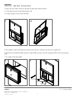
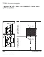
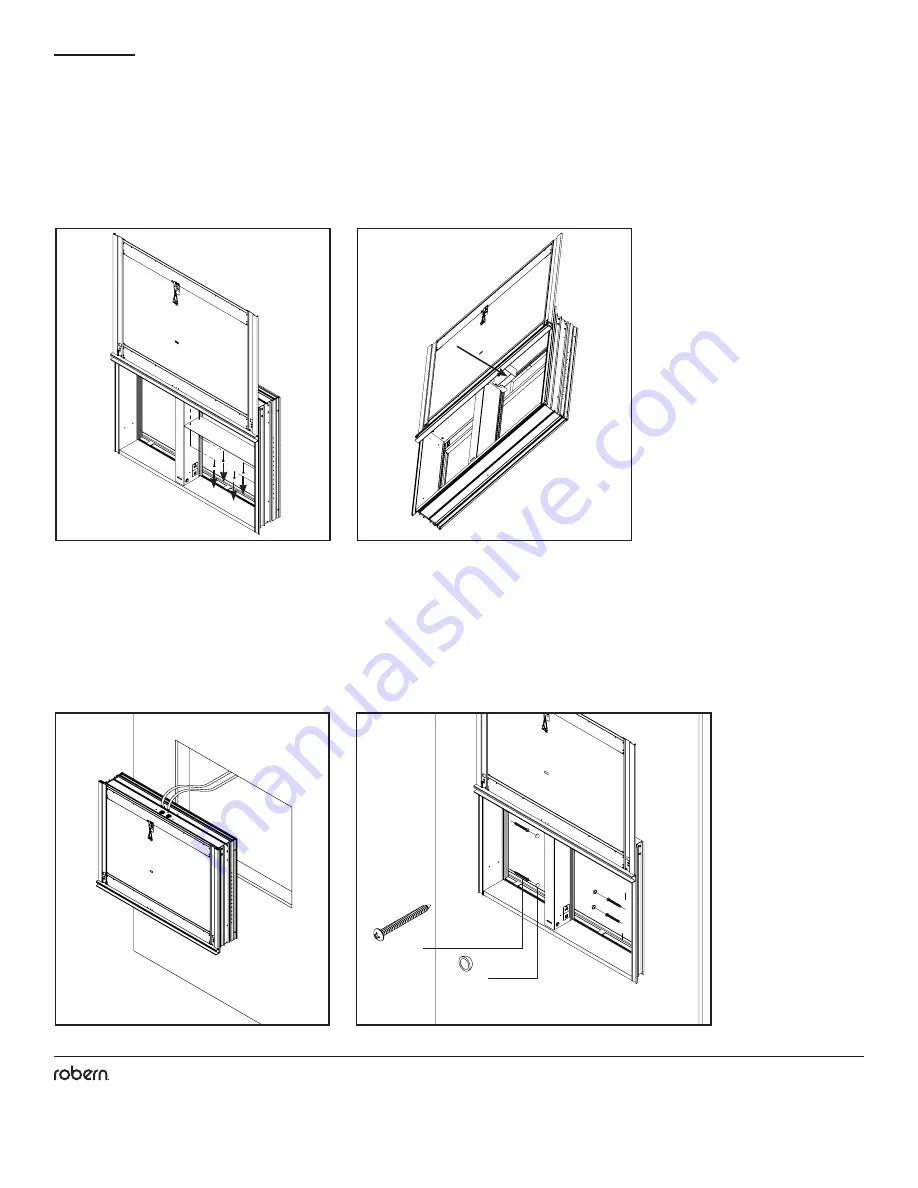
STEP 1C - SEMI-RECESS MOUNTING

5

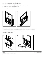
3. Remove the four screws to lower the right hand top ceiling panel inside the cabinet. 

3a. This will give access to the electrical connection box.

4. Continue to page 10 for Electrical Connections.

3

3a

5. Place cabinet in rough-in and make sure cabinet is plumb and level. If cabinet is not plumb, use supplied shims.

6. Install four screws (SS674) followed by the screw caps (SS672) as shown. 

7. Go to page 12 for final assembly.

6

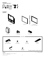
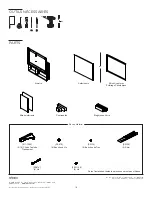
CB-211-1305

QTY: 6

CB-SS672

QTY: 6

CB-SS134

QTY: 6

CB-SS136

QTY: 2

CB-203-1349

QTY: 12

CB-SS674

QTY: 12

CB-SS712

QTY: 8

CB-203-1126

QTY: 6

CB-216-1188 HARDWARE BAG

CB-211-1305

QTY: 6

CB-SS672

QTY: 6

CB-SS134

QTY: 6

CB-SS136

QTY: 2

CB-203-1349

QTY: 12

CB-SS674

QTY: 12

CB-SS712

QTY: 8

CB-203-1126

QTY: 6

CB-216-1188 HARDWARE BAG

[SS672]

[SS674]

Содержание Uplift Tech

Страница 1: ...ion for how your cabinet s will be mounted The cabinets can be surface mounted recess mounted and semi recess mounted Electrical options may be provided with your cabinet s Save these instructions for...

Страница 2: ...ARDWARE BAG CB 211 1305 QTY 6 CB SS672 QTY 6 CB SS134 QTY 6 CB SS136 QTY 2 CB 203 1349 QTY 12 CB SS674 QTY 12 CB SS712 QTY 8 CB 203 1126 QTY 6 CB 216 1188 HARDWARE BAG CB 211 1305 QTY 6 CB SS672 QTY 6...

Страница 3: ...permanent wiring system or an equipment grounding conductor must be run with the circuit conductors and connected to the equipment grounding terminal or lead on the product CAUTION The cabinet must b...

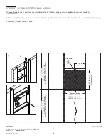
Страница 4: ...ame on all sides Find the speci c model dimensions in the diagram below to make the rough opening 2 Allow 24 610mm of electric wire STEP 1A RECESS MOUNTING 1 6 153mm 48 1 2 1232mm MINIMUM FROM FINISHE...

Страница 5: ...hims 6 Install four screws SS674 followed by the screw caps SS672 as shown Insert the hole plugs SS134 into the remaining four holes 7 Go to page 12 for final assembly STEP 1A RECESS MOUNTING 3 5 3a 6...

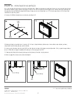
Страница 6: ...ting bar into the wall Be sure the mounting bar is level Make sure Z mounting bar is centered 3 Use four 10 X 2 screws SS674 provided to attach the Z bar mounting strip to the wall You can pre drill a...

Страница 7: ...ere is a strong resistance Do not overtighten 4 Lift the cabinet and place the cabinet onto the Z mounting bar 5 Pull bottom of cabinet away from the wall by about 1 2 and attach 4 lower mounting clip...

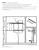
Страница 8: ...de kit USMK27D6SR 1 Make a rough opening and frame on all sides Find the speci c model dimensions in the diagram below to make the rough opening 2 Allow 24 610mm of electric wire 1 48 1 2 1232mm MINIM...

Страница 9: ...ectrical Connections 3 3a 5 Place cabinet in rough in and make sure cabinet is plumb and level If cabinet is not plumb use supplied shims 6 Install four screws SS674 followed by the screw caps SS672 a...

Страница 10: ...uct but have not been tested or verified It s recommended that the dimmer be within reach of your mirror so you can adjust the brightness For on off no dimmer operation a standard wall switch may be s...

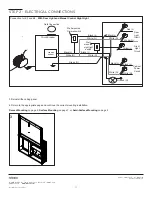
Страница 11: ...nting on page 5 Surface Mounting on page 7 or Semi Surface Mounting on page 9 STEP 2 ELECTRICAL CONNECTIONS Connection for E2 and E4 With Door Light and Manual Control Night Light 120 VAC 20A GFI Circ...

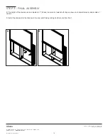
Страница 12: ...ng door mirror on door frame 3 Make door electrical connections to door mirror if equipped depends on model 4 Secure door mirror to door frame by installing 4 screws 203 1126 on the inside lower edge...

Страница 13: ...tall back mirrors in cabinet 7a Remove 4 screws securing right hand ceiling and place aside 7b Position right hand mirror into cabinet and reinstall ceiling Note for 24 cabinets skip to step 8 shelf c...

Страница 14: ...t no 209 1311 rA rev 06 13 19 Uplift Tech Cabinet 8 The height of the shelves can be adjusted in 1 25mm increments Install shelf clips as shown in channels holes in interior side of cabinet 9 Install...

Страница 15: ...n off This will not affect your programming Optional Manual night light operation using external wall switch A wall switch for the night light eliminates the need for the programming button However th...

Страница 16: ...ther than those authorized by Robern At the expiration of the one year warranty period Robern shall be under no further obligation under any warranty expressed or implied including the implied warrant...

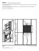
Страница 17: ...es pour savoir comment votre armoire sera mont e Les armoires peuvent tre mont es en surface encastr es et semi encastr es Des options lectriques peuvent tre fournies avec votre ou vos armoires Conser...

Страница 18: ...203 1126 QTY 6 CB 216 1188 HARDWARE BAG CB 211 1305 QTY 6 CB SS672 QTY 6 CB SS134 QTY 6 CB SS136 QTY 2 CB 203 1349 QTY 12 CB SS674 QTY 12 CB SS712 QTY 8 CB 203 1126 QTY 6 CB 216 1188 HARDWARE BAG CB 2...

Страница 19: ...manent m tallique mis la terre ou un conducteur de mise la terre de l quipement doit tre branch avec les conducteurs du circuit et connect la borne de mise la terre de l quipement ou au fil sur le pro...

Страница 20: ...ouverture brute et encadrez de tous les c t s Trouvez les dimensions sp cifiques du mod le dans le diagramme ci dessous pour effectuer l ouverture brute 2 Pr voyez 24 610mm de fil lectrique TAPE 1A M...

Страница 21: ...oire n est pas d aplomb utilisez les cales fournies 6 Installez quatre vis SS674 suivies des bouchons vis SS672 comme indiqu Ins rez les bouchons de trous SS134 dans les quatre trous restants 7 Allez...

Страница 22: ...e de retrait de la barre de montage dans le mur Assurez vous que la barre de montage est niveau Assurez vous que la barre de montage Z est centr e 3 Utilisez quatre vis n 10 X 2 SS674 fournies pour fi...

Страница 23: ...es vis n 10 et serrez jusqu ce qu il y ait une forte r sistance Ne pas trop serrer 4 Soulevez le bo tier et placez le sur la barre de montage en Z 5 loignez le bas du meuble du mur d environ 1 2 et fi...

Страница 24: ...kit lat ral semi encastr USMK27D6SR 1 Faites une ouverture brute et encadrez de tous les c t s Trouvez les dimensions sp cifiques du mod le dans le diagramme ci dessous pour effectuer l ouverture bru...

Страница 25: ...e 26 pour les connexions lectriques 3 3a 5 Placez l armoire dans le bo tier et assurez vous que l armoire est l aplomb et niveau Si l armoire n est pas d aplomb utilisez les cales fournies 6 Installez...

Страница 26: ...onctionner avec ce produit mais n ont pas t test s ou v rifi s Il est recommand de laisser le variateur la port e de votre miroir afin de pouvoir r gler la luminosit Pour le fonctionnement marche arr...

Страница 27: ...de montage correcte Montage Encastr la page 20 Montage en Surface la page 22 ou Montage Semi Encastr la page 24 TAPE 2 CONNECTIONS ELECTRIQUES Connexion pour E2 et E4 Avec Lumi re de Porte et Veilleus...

Страница 28: ...soigneusement le r troviseur au cadre de la porte 3 tablissez les connexions lectriques de la porte au r troviseur le cas ch ant cela d pend du mod le 4 Fixez le r troviseur au dormant en installant 4...

Страница 29: ...llez les r troviseurs dans l armoire 7a Retirez les 4 vis fixant le plafond droit et placez les de c t 7b Positionnez le miroir droit dans l armoire et r installez le plafond Remarque pour les armoire...

Страница 30: ...ev 06 13 19 Uplift Tech Cabinet Uplift Tech Cabinet 8 La hauteur des tag res peut tre ajust e par incr ments de 1 25mm Installez les attaches d tag re comme indiqu dans les rainures trous de la face i...

Страница 31: ...e Cela n affectera pas votre programmation Op ration manuelle de la veilleuse en option l aide d un commutateur mural externe Un interrupteur mural pour la veilleuse limine la n cessit du bouton de pr...

Страница 32: ...elles autoris es par Robern l expiration de la p riode de garantie d un an Robern n aura plus aucune obligation sous aucune garantie implicite ou explicite y compris la garantie implicite de qualit ma...

Страница 33: ...re c mo se montar n sus gabinetes Los armarios pueden montarse en superficie empotrar y semi empotrar Las opciones el ctricas pueden proporcionarse con su s gabinete s Guarde estas instrucciones para...

Страница 34: ...3 1126 QTY 6 CB 216 1188 HARDWARE BAG CB 211 1305 QTY 6 CB SS672 QTY 6 CB SS134 QTY 6 CB SS136 QTY 2 CB 203 1349 QTY 12 CB SS674 QTY 12 CB SS712 QTY 8 CB 203 1126 QTY 6 CB 216 1188 HARDWARE BAG CB 211...

Страница 35: ...cableado permanente de metal con conexi n a tierra o un conductor de conexi n a tierra del equipo debe ejecutarse con los conductores del circuito y conectado al terminal de conexi n a tierra del equ...

Страница 36: ...un marco en bruto en todos los lados Encuentre las dimensiones del modelo espec fico en el diagrama a continuaci n para hacer la apertura aproximada 2 Permita 24 610mm de cable el ctrico PASO 1A MONT...

Страница 37: ...no est a plomo use las calzas suministradas 6 Instale cuatro tornillos SS674 seguidos de los tapones de los tornillos SS672 como se muestra Inserte los tapones de los orificios SS134 en los cuatro ori...

Страница 38: ...nea de muesca en la barra de montaje en la pared Aseg rese de que la barra de montaje est nivelada Aseg rese de que la barra de montaje Z est centrada 3 Use los cuatro tornillos 10 X 2 SS674 provisto...

Страница 39: ...s hasta que haya una resistencia fuerte No apriete demasiado 4 Levante el gabinete y col quelo en la barra de montaje Z 5 Retire la parte inferior del gabinete de la pared aproximadamente 1 2 y coloqu...

Страница 40: ...lateral semi empotrado USMK27D6SR 1 Hacer una abertura y un marco en bruto en todos los lados Encuentre las dimensiones del modelo espec fico en el diagrama a continuaci n para hacer la apertura apro...

Страница 41: ...conexiones el ctricas 3 3a 5 Coloque el gabinete dentro de la preparaci n y aseg rese de que el gabinete est vertical y nivelado Si el gabinete no est a plomo use las calzas suministradas 6 Instale cu...

Страница 42: ...ste producto pero no se han probado ni verificado Se recomienda que el regulador est al alcance de su espejo para que pueda ajustar el brillo Para la operaci n de encendido apagado sin regulador se pu...

Страница 43: ...aje Empotrado en la p gina 36 Montaje en Superficie en la p gina 38 o Montaje Semi Empotrado en la p gina 40 PASO 2 CONEXIONES EL CTRICAS Conexi n para E2 y E4 Con Luz de Puerta y Luz de Control Manua...

Страница 44: ...nte colgar el espejo de la puerta en el marco de la puerta 3 Haga las conexiones el ctricas de la puerta al espejo de la puerta si est equipado depende del modelo 4 Fije el espejo de la puerta al marc...

Страница 45: ...iores en el gabinete 7a Retire los 4 tornillos que sujetan el techo de la mano derecha y col quelos a un lado 7b Coloque el espejo derecho en el gabinete y vuelva a instalar el techo Nota para gabinet...

Страница 46: ...rA rev 06 13 19 Uplift Tech Cabinet Uplift Tech Cabinet 8 La altura de los estantes se puede ajustar en incrementos de 1 25mm Instale los clips para estantes como se muestra en los canales agujeros en...

Страница 47: ...ncender apagar la luz nocturna Esto no afectar su programaci n Opcional Operaci n de luz nocturna manual con interruptor de pared externo Un interruptor de pared para la luz nocturna elimina la necesi...

Страница 48: ...ado o reparaciones que no sean las autorizadas por Robern Al vencimiento del per odo de garant a de un a o Robern no tendr ninguna obligaci n adicional bajo ninguna garant a expresa o impl cita inclui...

Отзывы: