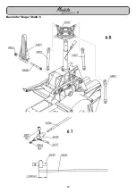
Baustufe: 4
Stage: 4
Stade: 4
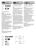
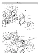
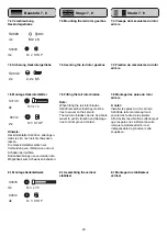
4.0 Assembling the top and bottom
chassis sections, fueltank, silencer
and/or exhaust manifold
Note:
The exhaust outlet may be on the right
side depending on the type of silencer
you are using. If you intend to fit a
tuned pipe the manifold (header)
should be installed at this stage.
The tuned pipe itself is installed during
the very last stage of assembly.
Tip:
We recommend that you connect the
fuel feed line to the carburettor now,
before the top and bottom chassis
sections are assembled, while access
is still good.
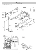
Note (sketch A):
Note that the travel „GB“ of the
bellcrank should be about 13 mm.
Select a linkage hole on the
carburettor arm which provides this,
as this arrangement provides optimum
travel adjustment for the throttle servo.
Adjust the pushrod length „GA“ to the
point where the bellcrank is at right-
angles to the chassis when the
carburettor arm is vertical.
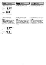
Note:
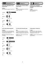
Place front structure extension S1029
in the bottom section S4012. Drill 1.5
mm Ø holes in the bottom section for
the self-tapping screws S1005.
4.0 Assemblage de la partie
supérieure, de la partie inférieure,
du réservoir et du silencieux et du
coude-collecteur
A noter:
En fonction du silencieux utilisé, la
sortie d‘échappement peut être
orientée vers la droite.
Avec un résonateur on installe au
cours de ce stade de montage
l‘adaptateur ou le coude-collecteur
approprié au lieu du silencieux.
Le résonateur sera monté tout à la fin.
Un conseil:
Pour améliorer l‘accessibilité, il est
possible dès maintenant, avant
d‘assembler la partie inférieure et la
partie supérieure du châssis, de
raccorder déjà le branchement du
carburateur au carburateur.
À noter: (cf. schéma A)
Pour obtenir un réglage efficace de la
course du servo des gaz, il faut choisir
le point d‘asservissement du palonnier
des gaz de telle manière que la
course „GB“ du palonnier de renvoi
soit de 13 mm environ. La longueur de
la tringle „GA“ doit être réglée de telle
manière que lorsque le palonnier des
gaz se trouve à la verticale de
palonnier de renvoi forme un angle
droit avec le châssis.
À noter :
installer la rallonge de superstructure
avant S1029 dans la partie inférieure
S4012. Porter les alésages pour les
vis autotaraudeuses
S1005 à Ø 1,5 mm dans la partie
inférieure.
19
4.0 Zusammenbau Oberteil,
Unterteil, Tank und Schalldämpfer
bzw. Krümmer
Hinweis:
Je nach verwendetem Schalldämpfer
sollte die Auslaßöffnung nach rechts
zeigen. Bei Verwendung eines
Resonanzrohres wird in dieser
Baustufe anstatt des Schalldämpfers
der passende Adapter bzw. Krümmer
angeschraubt.
Das Resonanzrohr wird ganz zum
Schluß montiert.
Tip:
Aufgrund der besseren Zugänglichkeit
kann vor Zusammenbau des Chassis-
Ober- und Unterteils der
Vergaseranschlußschlauch
bereits jetzt auf den Vergaser
aufgesteckt werden.
Hinweis: (Skizze A)
Um eine optimale Wegeinstellung für
das Gasservo zu erreichen, sollte der
Anlenkpunkt amVergaserhebel so
gewählt werden, daß der Weg “GB“
des Umlenkhebels ca. 13mm beträgt.
Die Gestängelänge “GA“ ist so
einzustellen, daß bei senkrecht
stehendem Vergaserhebel der
Umlenkhebel rechtwinklig zum
Chassis steht.
Hinweis:
Vorbauverlängerung S1029 in das
Unterteil S4012 einsetzen. Die
Bohrungen für die PT-Schrauben
S1005 mit Ø 1,5 mm im Unterteil
bohren.
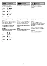
S0036
M 3 x 20
S0012
M 3 STOP
S0037
M 3 x 25
S3078
M 4 x 10
2x
2x
2x
4x
S0001
3.2 x 7 x 0.5
4x
S1005
PT 2.5 x 6.5
2x
Содержание Moskito Sport II
Страница 1: ...S 2884 II ...
Страница 8: ...Baustufe Stage Stade 1 8 II S1393 ...
Страница 10: ...Baustufe Stage Stade 1 10 II ...
Страница 12: ...Baustufe Stage Stade 1 12 II ...
Страница 14: ...Baustufe Stage Stade 2 14 II ...
Страница 16: ...Baustufe Stage Stade 3 16 II ...
Страница 18: ...Baustufe Stage Stade 4 18 II ...
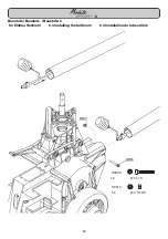
Страница 20: ...Baustufe Stage Stade 4 5 20 II ...
Страница 22: ...Baustufe Stage Stade 6 22 II ...
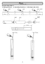
Страница 24: ...Baustufe Stage Stade 6 24 II 6 2 Montage Heckrohr 6 2 Assembling the tail boom 6 2 Montage du tube arrière ...
Страница 26: ...Baustufe Stage Stade 7 26 II ...
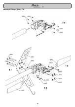
Страница 28: ...Baustufe Stage Stade 7 8 28 II ...
Страница 30: ...Baustufe Stage Stade 8 9 30 II ...
Страница 32: ...Baustufe Stage Stade 10 32 II ...
Страница 34: ...Baustufe Stage Stade 10 34 II ...
Страница 36: ...Baustufe Stage Stade 11 12 36 II ...
Страница 38: ...Baustufe Stage Stade 12 38 II S4536 ...
Страница 40: ...Baustufe Stage Stade 12 40 II ...
Страница 42: ...Baustufe Stage Stade 12 42 II ...
Страница 46: ...Baustufe Stage Stade 14 46 6 4 1 2 3 5 7 8 9 11 mm 14 0 II S3879 ...
Страница 48: ...48 Baustufe Stage Stade 14 P E N C G C G C G TAPE A 14 2 14 1 II ...
Страница 50: ...50 Baustufe Stage Stade 15 15 A II ...
Страница 52: ...Baustufe Stage Stade 15 52 P A Pmax 9 0 PC GD Gmax 9 0 15 1 PC 8 5 mm GD 10 14 mm PA 63mm II PA ...
Страница 56: ...56 Baustufe Stage Stade 15 HB Re 9 0 HA Li Re 15 3 HA 11 mm HB 20 mm II ...
Страница 58: ...Baustufe Stage Stade 16 58 B A 16 0 II ...

