background image


66 

User's Guide Fireface 400   

© RME


Back to AN1/2. Now you can change all the faders of all inputs and playback channels just as 
you like, thus making any input and playback signals audible via the outputs AN1/2. The pano-
rama can be changed too. Click into the area above the fader and drag the green bar in order to 
set the panorama between left and right. The level meters of the third row display the level 
changes in real-time. 
 
You see, it is very easy to set up a specific submix for whatever output: select output channel, 
set up fader and pans of inputs and playbacks – ready! 
 
For advanced users sometimes it makes sense to work without Submix View. Example: you 
want to see and set up some channels of different submixes simultaneously, without the need 
to change between them all the time. Switch off the Submix View by a click on the green button. 
Now the black routing fields below the faders no longer show the same entry (AN1/2), but com-
pletely different ones. The fader and pan position is the one of the individually shown routing 
destination. 
 
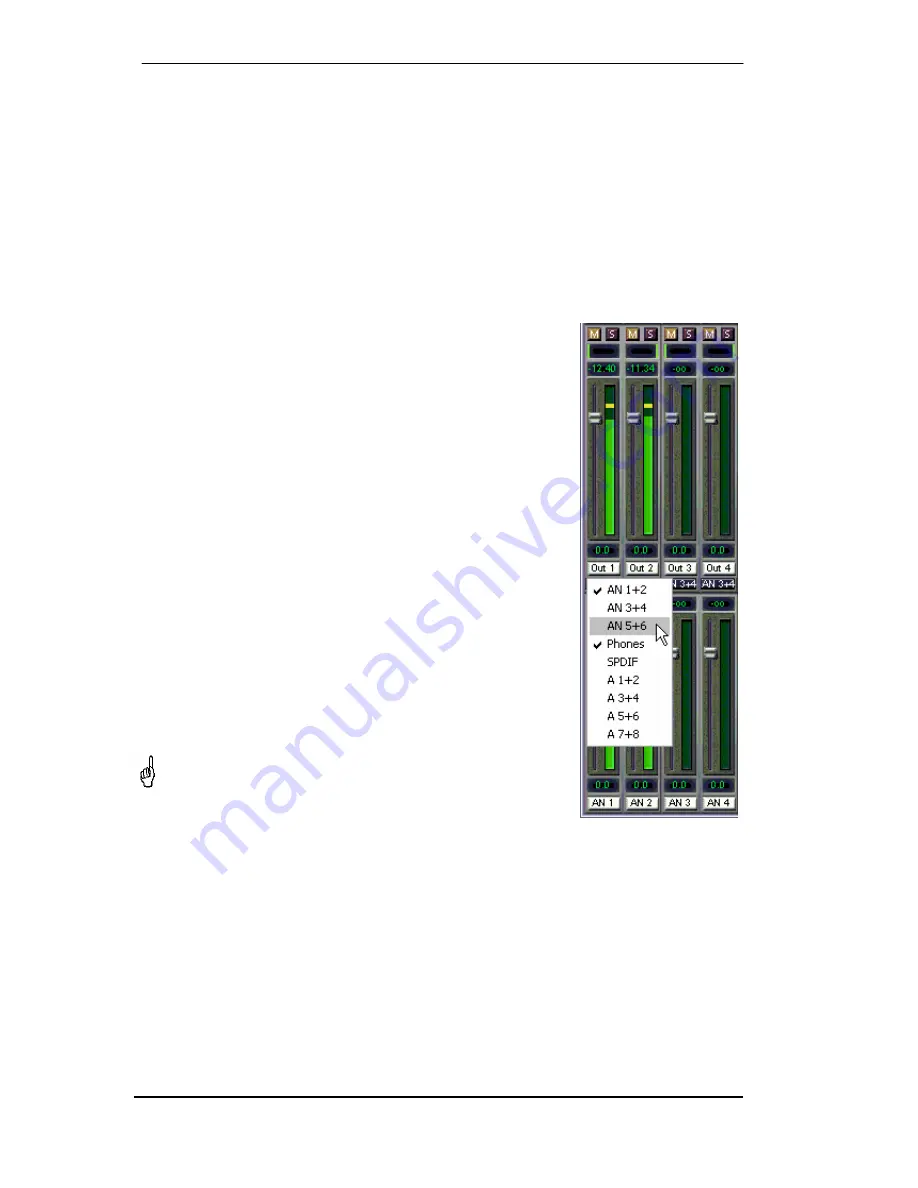
In playback channel 1 (middle row), labeled Out 1, click onto the 
routing field below the label. A list pops up, showing a checkmark in 
front of 'AN 1+2' and 'Phones'. So currently playback channel 1 is 
sent to these two routing destinations. Click onto 'AN 5+6'. The list 
disappears, the routing field no longer shows 'AN1+2', but 'AN 5+6'. 
Now move the fader with the mouse. As soon as the fader value is 
unequal m.a., the present state is being stored and routing is acti-
vated. Move the fader button to around 0 dB. The present gain value 
is displayed below the fader in green letters. 
 
In the lower row, on channel 5, you can see the level of what you 
are hearing from output 5. The level meter of the hardware output 
shows the outgoing level. Click into the area above the fader and 
drag the mouse in order to set the panorama, in this case the rout-
ing between channels 5 and 6. The present pan value is also being 
displayed below the fader. 
 
Please carry out the same steps for Out 2 now, in order to route it to 
output 6 as well. 
 
In short: While editing the Submix AN5/AN6 you have direct access 
to other submixes on other channels, because their routing fields 
are set to different destinations. And you get a direct view of how 
their faders and panoramas are set up. 
 

This kind of visual presentation is a mighty one, but for many 
users it is hard to understand, and it requires a deep under-
standing of complex routing visualizations. Therefore we usu-
ally recommend to work in Submix View

 
Often signals are stereo, i. e. a pair of two channels. It is therefore helpful to be able to make 
the routing settings for two channels at once. Hold down the Ctrl-key and click into the routing 
field of Out 3. The routing list pops up with a checkmark at 'AN 3+4'. Select 'AN 5+6'. Now, Out 
4 has already been set to 'AN 5+6' as well. 
 
When you want to set the fader to exactly 0 dB, this can be difficult, depending on the mouse 
configuration. Move the fader close to the 0 position and now press the Shift-key. This activates 
the fine mode, which stretches the mouse movements by a factor of 8. In this mode, a gain 
setting accurate to 0.1 dB is no problem at all. 


Содержание Fireface 400

Страница 1: ...400 Digital I O System 8 8 2 Channels Analog ADAT SPDIF Interface 24 Bit 192 kHz Digital Audio 36 x 18 Matrix Router MIDI I O Stand Alone Operation MIDI Remote Control Stand Alone MIDI Controlled Operation TotalMix 24 Bit 192 kHz 9 SyncAlign ZLM SyncCheck SteadyClock ...

Страница 2: ...nput Gain 19 11 3 Settings dialog DDS 19 11 4 Clock Modes Synchronization 21 11 5 Limit Bandwidth 22 12 Operation and Usage 12 1 Playback 23 12 2 DVD Playback AC 3 DTS 24 12 3 Low Latency under MME 25 12 4 Notes on WDM 26 12 5 Multi client Operation 27 12 6 Digital Recording 28 12 7 Analog Recording 29 13 Operation under ASIO 2 0 13 1 General 29 13 2 Known Problems 30 14 Operation under GSIF 30 15...

Страница 3: ...26 3 2 channel Mic Preamp 53 26 4 Monitor Mixer 53 26 5 Digital Format Converter 53 26 6 Analog digital Routing Matrix 53 27 Analog Inputs 27 1 Line Rear 54 27 2 Microphone Line Front 54 27 3 Instrument Line Front 55 28 Analog Outputs 28 1 Line 56 28 2 Phones 7 8 56 29 Digital Connections 29 1 ADAT 57 29 2 SPDIF 57 29 3 MIDI 58 30 Word Clock 30 1 Word Clock Input and Output 59 30 2 Technical Descr...

Страница 4: ...Mapping 81 34 3 Setup 82 34 4 Operation 82 34 5 Simple MIDI Control 83 34 6 Loopback Detection 83 34 7 Stand Alone MIDI Control 84 Technical Reference 35 Tech Info 88 36 Technical Specifications 36 1 Analog 89 36 2 MIDI 90 36 3 Digital 90 36 4 Digital Inputs 90 36 5 Digital Outputs 91 36 6 Transfer Modes Resolution Bits per Sample 91 36 7 General 91 37 Technical Background 37 1 Lock and SyncCheck ...

Страница 5: ...User s Guide Fireface 400 RME 5 User s Guide Fireface 400 General ...

Страница 6: ... 3 PPC or Intel 1 OHCI compatible FireWire Port 400 1394a or 800 1394b Pentium III 866 MHz or better G4 Dual 867 or better Note Examples and detailed descriptions of suitable audio desktop systems can be found in the Tech Info RME Reference PCs Hardware recommendations Information on compatibility and performance of notebooks laptops is included in RMEs Tech Infos about notebooks HDSP System Noteb...

Страница 7: ...tting up the monitor volume Pushing the knob changes the encoder from CHANNEL to LEVEL mode and back Pushing the knob for more than a second activates either the single channel or stereo setup mode The State LEDs WC SPDIF ADAT indicate a valid input signal separately for each digital input Additionally RME s exclusive SyncCheck indicates if one of these inputs is locked but not synchronous to the ...

Страница 8: ... allows to activate internal termination 75 Ohms When termination is activated the yellow LED besides the switch lights up MIDI I O Provides two MIDI inputs and outputs via the included break out cable FW 400 6 pin FireWire sockets for connection to the computer The second socket provides hub func tionality to connect another Fire Wire device POWER switch The Fireface 400 can be powered by an exte...

Страница 9: ...using the rotary encoder This output is a very low impedance type which can also be used to con nect headphones The function Store in Flash Memory Settings dialog and Flash current mixer state TotalMix allow to store the current settings into the Fireface 400 The unit then remembers all settings and loads these automatically when switched on With this the Fireface 400 can be used stand alone after...

Страница 10: ...ered or otherwise are the property of their respective owners RME DIGI96 SyncAlign ZLM SyncCheck DIGICheck and Hammerfall are registered trademarks of RME Intelligent Audio Solutions TMS TotalMix SteadyClock and Fireface are trademarks of RME Intelligent Audio Solutions Alesis and ADAT are registered trademarks of Alesis Corp ADAT optical is a trademark of Alesis Corp Microsoft Windows and Windows...

Страница 11: ...particular installation If this equipment does cause harmful interference to radio or television reception which can be de termined by turning the equipment off and on the user is encouraged to try to correct the inter ference by one or more of the following measures Reorient or relocate the receiving antenna Increase the seperation between the equipment and receiver Connect the equipment into an ...

Страница 12: ...12 User s Guide Fireface 400 RME ...

Страница 13: ...User s Guide Fireface 400 RME 13 User s Guide Fireface 400 Installation and Operation Windows ...

Страница 14: ...tion the green arrow symbol appears in the task bar dialog Remove hardware because Windows has detected an external hardware Insert the RME Driver CD into your CD ROM drive and follow further instructions which appear on your computer screen The driver files are located in the directory Fireface W2k on the RME Driver CD Windows now installs the driver of the Fireface 400 and registers it as a new ...

Страница 15: ...ialog and the registration of the ASIO driver These entries can be re moved from the registry by a software deinstallation request This request can be found like all deinstallation entries in Control Panel Software Click on the entry RME Fireface 10 4 Firmware Update The Flash Update Tool updates the firmware of the Fireface 400 to the latest version It requires an already installed driver Start t...

Страница 16: ... immediately confirmation e g by clicking on OK or exiting the dialog is not required However settings should not be changed during playback or record if it can be avoided as this can cause unwanted noises Also please note that even in Stop mode several programs keep the recording and playback devices open which means that any new settings might not be applied imme diately The status displays at t...

Страница 17: ...phono plug After selecting Optical it is also routed to the optical TOSLINK out put For further details about the settings Professional Emphasis and Non Audio please refer to chapter 29 2 SPDIF Freq Displays the sample rate of the sig nal at the SPDIF input Input Level 5 8 Defines the reference level for the rear analog inputs 5 8 Output Level 1 6 Defines the reference level for the rear analog ou...

Страница 18: ...he desired clock source If the selected source isn t available the unit will change to the next available one The current clock source and sample rate is displayed in the AutoSync Ref display The automatic clock selection checks and changes between the clock sources Word Clock ADAT and SPDIF Word Clock Out The word clock output signal usu ally equals the current sample rate Selecting Single Speed ...

Страница 19: ...p in case both channels shall have the same set ting values The current gain is displayed in dB below the fader Further information is found in chapter 27 3 11 3 Settings dialog DDS Usually soundcards and audio interfaces generate their internal clock master mode by a quartz Therefore the internal clock can be set to 44 1 kHz or 48 kHz but not to a value in be tween SteadyClock RME s sensational L...

Страница 20: ...on the faders A mouse click within the fader area above or below the fader know will move the fader with the smallest step size up or down Holding the Ctrl key while clicking will cause the fader to jump to its center 0 Application examples DDS allows for a simultaneous change of speed and tune during record and playback From alignment to other sources up to creative effects everything is possible...

Страница 21: ...e Fireface s clock mode is set to Master all other devices must be set to Slave The Fireface s ADAT optical and SPDIF inputs operate simultaneously Because there is no input selector however the Fireface 400 has to be told which of the signals is the sync refer ence a digital device can only be clocked from a single source Via Pref Sync Ref preferred synchronization reference a preferred input can...

Страница 22: ...lows any frequency between 28 kHz and 200 kHz At 88 2 or 96 kHz If the ADAT input has been selected in Pref Sync Ref the sample frequency shown in the SPDIF Freq field differs from the one shown in AutoSync Ref The unit automati cally switches to S MUX mode here because ADAT optical inputs and outputs are only speci fied up to 48 kHz Data from to a single input output is spread over two channels t...

Страница 23: ...g or digital ADAT SPDIF port depending on which has been selected as play back device Increasing the number and or size of audio buff ers may prevent the au dio signal from breaking up but also increases latency i e output is de layed For synchronized playback of audio and MIDI or similar be sure to activate the checkbox Get position from audio driver The Fireface s ADAT optical interface supports...

Страница 24: ...00 has to be selected in Control Panel Sounds and Multimedia Audio Also check use preferred device only PowerDVD s audio properties now lists several multichannel modes If one of these is selected PowerDVD sends the decoded analog multichannel data to the Fireface The option Interleaved in the Settings dialog has to be activated Certain MME playback devices of the Fireface support multichannel pla...

Страница 25: ...ll show a higher basic CPU load then Therefore we rec ommend to use at least 64 samples Please note that this setting only defines the buffer size of the hardware The true and effective latency is configured within the MME application Attention the DMA buffers must not be larger than the application s buffers Playback will be stuttering and audio will be distorted Example when you set the Fireface...

Страница 26: ...d therefore will operate better when using a WDM device Please note that selecting the Fireface to be used as system playback device is against our recommendations as professional interfaces should not be disturbed by system events The program Sonar from Cakewalk is unique in many ways Sonar uses the so called WDM Kernel Streaming bypassing the WDM mixer thus achieves a similar performance as ASIO...

Страница 27: ...able to analyse and display playback data from any software no matter which format the software uses Multi Client and Multi Channel using WDM The WDM Streaming devices of our driver can operate as usual stereo devices or as 8 channel devices The option Interleaved in the Settings dialog determines the current mode Interleaved not active The WDM devices operate as usual stereo devices The multi cli...

Страница 28: ...dio attributes or similar dialog The screenshot on the right shows a typical dia log used for changing basic parameters such as sample frequency and resolution in an audio ap plication Any bit resolution can be selected providing it is supported by both the audio hardware and the software Even if the input signal is 24 bit the application can still be set to record at 16 bit reso lution The lower ...

Страница 29: ...ation Fireface 400 supports ASIO Direct Monitoring ADM Please note that at the time of writing this manual Nuendo Cubase and Logic either do not support ADM completely or not fully error free Using emulated MIDI drivers can cause a drift and delay between au dio and MIDI Try the non emulated MME MIDI ports in such a case or use an ad vanced setting like Sys tem Timestamp When the sample frequency ...

Страница 30: ...Gigasampler Interface Windows 2000 XP The GSIF interface of the Fireface 400 allows direct operation with Gigastudio with up to 28 channels 96 kHz and 24 bit The new GSIF 2 0 is also supported with both audio and MIDI Gigastudio requires a lot of a computer s CPU performance Optimum performance is achieved with a stand alone GSIF PC The GSIF latency of the Fireface 400 can be set between 48 and 25...

Страница 31: ... some channels Using more than one Fireface 4000 together with a FireWire hard drive hub functionality can cause audio problems More information about numbers of channels and bus load can be found in chapter 37 4 The driver takes care of the numbering of all Firefaces so that it doesn t change The unit with the lowest serial number is always Fireface 1 Please note If the Fireface 1 is switched off...

Страница 32: ...figurable causing near zero CPU load because calculated from the Fireface hardware Vector Audio Scope World wide unique Goniometer showing the typical afterglow of a oscilloscope tube Includes Correlation meter and level meter Spectral Analyser World wide unique 10 20 or 30 band display in analog bandpass filter technology 192 kHz capable Bit Statistics Noise Shows the true resolution of audio sig...

Страница 33: ...de to Master Crackle during record or playback Increase the number and size of buffers in the Settings dialog or in the application Try different cables coaxial or optical to rule out any defects here Check that cables devices have not been connected in a closed loop If so set the system s clock mode to Master Increase the buffer size of the hard disk cache Activate Busmaster mode for the hard dis...

Страница 34: ...on of the card do not attempt to install the drivers manually An installation of drivers for non recognized hardware will cause a blue screen when booting Windows Possible causes for a Fireface not found automatically The FireWire port is not active in the system drivers of the FireWire PCI or CardBus card have not been installed The FireWire cable is not or not correctly inserted into the socket ...

Страница 35: ...l paths in ASIO double speed mode 88 2 96 kHz The devices available via the ASIO driver have been designed to avoid conflicts in normal operation Chan nels 5 6 7 and 8 of the ADAT port have no function anymore but are used by the hardware to transmit data at double sample rate Record and playback are identical ...

Страница 36: ...in MME double speed mode 88 2 96 kHz The devices available via the MME wave driver have been designed to avoid conflicts in normal operation Channels 5 6 7 and 8 of the ADAT port have no function anymore but are used by the hard ware to transmit data at double sample rate Record and playback are identical ...

Страница 37: ...User s Guide Fireface 400 RME 37 User s Guide Fireface 400 Mac OS X Installation and Operation ...

Страница 38: ...t driver version from the RME website If done the procedure is as follows Double click onto fireface_xx gz to expand the archive file to fireface_xx tar and the folder Fireface which includes the driver file fireface mpkg Installation works automatically by a double click on this file During driver installation the programs Settings dialog and Fireface mixer TotalMix will also be installed Both pr...

Страница 39: ...ther it needs an update or not If so simply press the Update but ton A progress bar will indicate when the flash process is finished Verify Ok If more than one Fireface is installed all units can be flashed by changing to the next tab and repeating the process After the update the unit needs to be reset This is done by powering down the Fireface for a few seconds A reboot of the computer is not ne...

Страница 40: ...applied immediately confirmation e g by exiting the dialog is not required However settings should not be changed during playback or record if it can be avoided as this can cause un wanted noises The upper part of the dialog config ures the analog inputs and outputs the lower part controls the digital setup The status displays at the bottom of the dialog box give the user precise information about...

Страница 41: ...the opti cal TOSLINK input SPDIF Out The SPDIF output signal is constantly available at the phono plug After selecting Optical it is also routed to the optical TOSLINK output For further details about the settings Professional Emphasis and Non Audio please refer to chapter 29 2 SPDIF Freq Displays the sample rate of the SPDIF or AES input signal Clock Mode The unit can be configured to use its int...

Страница 42: ...er using its own clock or Slave AutoSync Ref Limit Bandwidth Allows to reduce the amount of bandwidth used on the FireWire bus See chapter 22 4 All channels default activates all 18 input and output channels Analog SPDIF activates all 10 analog channels plus SPDIF Analog 1 8 activates only the first eight analog channels Read Flash Memory A click on this button causes all settings to change to the...

Страница 43: ...he reference level for the rear analog inputs 5 8 22 3 Settings dialog DDS Usually soundcards and audio interfaces generate their internal clock master mode by a quartz Therefore the internal clock can be set to 44 1 kHz or 48 kHz but not to a value in be tween SteadyClock RME s sensational Low Jitter Clock System is based on a Direct Digital Synthesizer DDS This superior circuitry can generate ne...

Страница 44: ...n the faders A mouse click within the fader area above or below the fader know will move the fader with the smallest step size up or down Holding the Ctrl key while clicking will cause the fader to jump to its center 0 Application examples DDS allows for a simultaneous change of speed and tune during record and playback From alignment to other sources up to creative effects everything is possible ...

Страница 45: ...eface s clock mode is set to Master all other devices must be set to Slave The Fireface s ADAT optical and SPDIF inputs operate simultaneously Because there is no input selector however the Fireface 400 has to be told which of the signals is the sync refer ence a digital device can only be clocked from a single source Via Pref Sync Ref preferred synchronization reference a preferred input can be d...

Страница 46: ...between 28 kHz and 200 kHz At 88 2 or 96 kHz If the ADAT input has been selected in Pref Sync Ref the sample frequency shown in the SPDIF Freq field dif fers from the one shown in AutoSync Ref The unit automatically switches to S MUX mode here because ADAT optical inputs and outputs are only specified up to 48 kHz Data from to a single input output is spread over two channels the internal frequenc...

Страница 47: ...es Nonetheless this driver file can be removed by simply dragging it to the trash bin This can be helpful in case a driver installation fails An incomplete installation can currently 10 3 2 only be detected indirectly The installation routine does not open a message window with a note about a restart of the computer This indicates that the driver file was not copied and the driver was not installe...

Страница 48: ...ny FireWire port found on Apple Mac com puters This is not true for older models like the G3 Pismo as their FireWire controller is not OHCI compatible Although we tested compatibility with lots of models total compatibility can not be guaranteed In case of trouble please contact RME 23 6 Various Information The driver has been tested under 10 3 only Older versions of OS X are not and will not be s...

Страница 49: ... The ADAT playback devices are still us able by routing and mixing them in TotalMix to other outputs Playback works but record doesn t Check that there is a valid signal at the input If so the current sample frequency is dis played in the Settings dialog Check whether the Fireface 400 has been selected as recording device in the audio applica tion Check whether the sample frequency set in the audi...

Страница 50: ...Hz This diagram shows the signal paths in double speed mode 88 2 96 kHz Channels 5 6 7 and 8 of the ADAT port have no function anymore in Core Audio but are used by the hardware to transmit data at double sample rate Signal routing is identical for record and playback ...

Страница 51: ...User s Guide Fireface 400 RME 51 User s Guide Fireface 400 Stand Alone Operation Connections and TotalMix ...

Страница 52: ...tes to the Fireface s MIDI output To activate this mode first activate MIDI control in TotalMix Enable MIDI control then transfer this state via Flash current mixer state into the unit Turning this mode off is done in the same way but with MIDI control deacti vated 26 1 Front Panel Operation The knob on the front a so called rotary encoder serves to set the input gains and output vol umes directly...

Страница 53: ...puts This turns the Fireface 400 into a 2 channel microphone preamp The AD and DA conversion will cause a small delay of the signals of around 0 35 ms at 192 kHz see chapter 37 2 But this is not really relevant as it is the same delay that would be caused by changing the microphone s posi tion by about 12 centimeter 5 inches 26 4 Monitor Mixer TotalMix allows ANY configuration of all I Os of the F...

Страница 54: ... dBu 13 dBu 9 dB 10 dBV 2 dBV 12 dB With 4 dBu selected the according headroom meets the latest EBU recommendations for Broadcast usage At 10 dBV a headroom of 12 dB is common practice each mixing desk op erating at 10 dBV is able to send and receive much higher levels Lo Gain is best suited for professional users who prefer to work balanced and at highest levels Lo Gain provides 15 dB headroom at...

Страница 55: ... dBu Inst Pad Instrument The main difference between a line and instrument input is the input s impedance Via the op tion Inst 3 and Inst 4 in the Settings dialog the input impedance changes from 10 kOhm to 470 kOhm At the same time the input sensitivity rises to 10 dBV Using active instruments this setting can already cause overloads Therefore the option Pad is still available reducing the sensit...

Страница 56: ... suited for professional users who prefer to work balanced and at highest levels Lo Gain provides 15 dB headroom at 4 dBu nominal level The above levels are also found in our ADI 8 series of AD DA converters the Multiface and even in our Mic Preamps QuadMic and OctaMic Therefore all RME devices are fully compati ble to each other 28 2 Phones 7 8 Channels 7 8 of the Fireface are available on the fr...

Страница 57: ...Speed signal this port carries channels 1 to 4 29 2 SPDIF The SPDIF input is configured in the Settings dialog available by a click on the fire symbol in the Task Bar s system tray The Fireface 400 accepts all commonly used digital sources as well as SPDIF and AES EBU Channel status and copy protection are ignored To receive signals in AES EBU format an adapter cable is required Pins 2 and 3 of a ...

Страница 58: ...ected to the Fireface 400 thanks to the trans former balanced coaxial outputs and the Professional format option with doubled output volt age Output cables should have the same pinout as those used for input see above but with a male XLR plug instead of a female one Note that most consumer HiFi equipment with optical or phono SPDIF inputs will only accept signals in Consumer format The audio bit i...

Страница 59: ...and care fully push the blue switch so that it snaps into its lock position The yellow LED will be lit when termination is active Another push will release it again and de activate the termination Output The word clock output of the Fireface is constantly active providing the current sample fre quency as word clock signal As a result in Master mode the provided word clock is defined by the current...

Страница 60: ... also has some disadvantages The word clock is based on a fraction of the really needed clock For example SPDIF 44 1 kHz word clock a simple square wave signal has to be multiplied by 256 inside the device using a spe cial PLL to about 11 2 MHz This signal then replaces the one from the quartz crystal Big disadvantage because of the high multiplication factor the reconstructed clock will have grea...

Страница 61: ...e built into the device and cannot be switched off In this case the network load is often 2 x 75 Ohms and the user is forced to buy a special word clock distributor Note that such a device is generally recommended for bigger studios The Fireface s word clock input can be high impedance or terminated internally ensuring maximum flexibility If termination is necessary e g because the Fireface is the...

Страница 62: ...e most complete implementation of the ADM functions Integration of external devices Use TotalMix to insert external effects devices be it in the playback or in the record path Depending on the current application the functionality equals insert or effects send and effects return for example as used during real time monitoring when adding some reverb to the vocals Every single input channel playbac...

Страница 63: ...User s Guide Fireface 400 RME 63 ...

Страница 64: ...n from an Inline desk so that the row Software Playback equals the Tape Return of a real mixing desk Top row Hardware inputs The level shown is that of the input signal i e fader independ ent Via fader and routing field any input channel can be routed and mixed to any hardware output bottom row Middle row Playback channels playback tracks of the audio software Via fader and routing field any playb...

Страница 65: ...ix This chapter is a practical guide and introduction on how to use TotalMix and on how TotalMix works Starting up TotalMix the last settings are recalled automatically When executing the application for the first time a default file is loaded sending all playback tracks 1 1 to the corresponding hardware outputs with 0 dB gain and activating phones monitoring Hold down Ctrl and click on preset but...

Страница 66: ...and routing is acti vated Move the fader button to around 0 dB The present gain value is displayed below the fader in green letters In the lower row on channel 5 you can see the level of what you are hearing from output 5 The level meter of the hardware output shows the outgoing level Click into the area above the fader and drag the mouse in order to set the panorama in this case the rout ing betw...

Страница 67: ...n the routing window pull the fader down open the routing window again the checkmark is gone The number of ADAT channels is reduced automatically when entering Double Speed mode 96 kHz The display is adjusted accordingly and all fader settings remain stored Changing into Quad Speed mode 192 kHz all ADAT channels vanish TotalMix then displayes a total of only 10 channels 31 5 Submix View Such a wid...

Страница 68: ...ignal distribution complete input monitoring a stereo and mono mix and various submixes without any problem Also here RME s love for details can be seen If any parameter is being altered after loading a preset e g moving a fader the preset display flashes in order to announce that something has been changed still showing which state the pre sent mix is based on If no preset button is lit another p...

Страница 69: ...ix active Note This preset is Default offering the standard functionality of a I O system Preset 2 Description All channels routed 1 1 input and playback monitoring via Phones As Preset 1 plus submix of all inputs 0 dB to channels 7 8 Phones Preset 3 Description All channels routed 1 1 input and playback monitoring via Phones and outputs As Preset 2 but all inputs set to 0 dB 1 1 monitoring Preset...

Страница 70: ...ed with the channel s input fader Monitor Phones 1 2 3 Use the drop down menu to select the hardware outputs where the submixes are sent to These submixes are usually phones mixdowns for the musicians A click on the button allows to hear the specific submix via the Monitor Main outputs So when setting up or modifying the submix for the musician this process can be monitored easily and any time Or ...

Страница 71: ...right mouse click on the white name field brings up the dialog box Enter Name Any name can be entered in this dialog Enter Return closes the dialog box the white label now shows the first letters of the new name ESC cancels the process and closes the dialog box Moving the mouse above the label brings up a tool tip with the complete name The hardware outputs third row can be edited in the same way ...

Страница 72: ...otalMix also supports combinations of these keys If you press Ctrl and Alt at the same time clicking with the mouse makes the faders jump to 0 dB pairwise and they can be set pairwise by Shift Alt in fine mode Also very useful the faders have two mouse areas The first area is the fader button which can be grabbed at any place without changing the current position This avoids unwanted changes when ...

Страница 73: ...obally de activated Link Faders Selecting this option all faders will be treated as stereo pairs and moved pair wise Hotkey L MS Processing Macro for a quick configuration of routing and phase for Mid Side encoding and decoding See chapter 33 7 Level Meter Setup Configuration of the Level Meters Hotkey F2 See chapter 31 14 Preferences Opens a dialog box to configure several functions like Pan Law ...

Страница 74: ...adout is usually corrected by 3 dB so that a full scale sine signal shows 0 dBFS on both Peak and RMS meters This setting also yields directly readable signal to noise values Otherwise the value shown with noise is 3 dB better than it actually is because the reference is not 0 dB but 3 dB For example in WaveLab The value displayed in the text field is independent of the setting 40 60 dB it represe...

Страница 75: ...reen 0 0 dB field Standard 1 1 routing Black gain field Shows the current gain value as dB Orange gain field This routing is muted Blue field Phase 180 inverted To maintain overview when the window size has been reduced the left and upper labels are floating They won t left the visible area when scrolling 32 3 Operation Using the Matrix is a breeze It is very easy to indentify the current crosspoi...

Страница 76: ... unity gain Plus two rows vertically all at the same level setting You just need 2 seconds to be sure no unwanted routing is active anywhere and that all levels match precisely Example 2 The Matrix allows you to set up routings which would be nearly impossible to achieve by fiddling around with level and pan Let s say you want to send input 1 to output 1 at 0 dB to output 2 at 3 dB to output 3 at ...

Страница 77: ...pen the menu Edit It shows Copy In 1 Now select the desired new input for example In 8 The menu now shows Paste In 1 to In 8 Click on it done If you are familiar with this functionality just use Ctrl C and Ctrl V Else the self updating menu will always let you know what actually will happen Tip Have the Matrix window open as second window when doing this It will show the new rout ings immediately ...

Страница 78: ...nding channel is no longer sent to the recording software but still passed through to TotalMix Therefore TotalMix can be used to route this input signal to any hardware output Using the subgroup recording the input can still be recorded on a different channel As each of the 18 hardware outputs can be routed to the record software and none of these hardware inputs get lost TotalMix offers an overal...

Страница 79: ...d the panorama fully to the right Adjust the input level at the reverb unit to an optimal setting Next the output of the reverb unit is connected to a free stereo input for example 5 6 Use the To talMix level meters to adjust a matching output level at the reverb unit Now click on channels 7 8 in the bottom row and move the fader of inputs 5 6 until the reverb effect gets a bit too loud in the hea...

Страница 80: ...e channel represents L R During record the monitoring needs to be done in conventional stereo As TotalMix can invert the phase it also offers the functionality of a M S decoder The menu Options includes a macro to simplify the setup First select the two input channels in the picture to the right Analog In 3 and 4 having the current routing destination Analog Out 1 2 Now the string MS Processing In...

Страница 81: ...lements Element Meaning in TotalMix Channel faders 1 8 volume Master fader Main Monitor channel s faders SEL 1 8 DYNAMICS reset fader to Unity Gain V Pots 1 8 pan pressing V Pot knobs pan center CHANNEL LEFT or REWIND move one channel left CHANNEL RIGHT or FAST FORWARD move one channel right BANK LEFT or ARROW LEFT move eight channels left BANK RIGHT or ARROW RIGHT move eight channels right ARROW ...

Страница 82: ...feature causes heavy overload of the MIDI port when ganging more than 2 faders In such a case or when using the Behringer BCF2000 turn off this option When Full LC Display Support is turned off only a brief information about the first fader of the block channel and row is sent This brief information is also available on the LED display of the Behringer BCF2000 Tip for Mac OS X users LC Xview www o...

Страница 83: ... 3 Monitor Phones 2 40 64 E 3 Monitor Phones 3 41 65 F 3 Preset 1 36 54 F 2 Preset 2 37 55 G 2 Preset 3 38 56 G 2 Preset 4 39 57 A 2 Preset 5 3A 58 A 2 Preset 6 3B 59 B 2 Preset 7 3C 60 C 3 Preset 8 3D 61 C 3 An example of a small MIDI controller covering such MIDI functionality and even some more is the Behringer BCN44 This little box has 4 pots and 8 buttons for all the above functions for less ...

Страница 84: ...of the routing destination i e the current submix Sending of LED and display data to the MIDI controller The second row software playback is skipped in stand alone operation The Fireface 400 sends display data as brief information enabling an easy navigation through lines and rows Other data like PAN and miscellaneous status LEDs are supported as well In stand alone mode the unit always operates i...

Страница 85: ...l Change Pan CC 10 With this the most important volume settings of the Fireface are controlable from nearly any MIDI equipped hardware device The faders are controlled via differrent MIDI channels Hardware Output equals third row volume only Analog Out 9 10 Phones MIDI channel 1 Analog Out 1 2 MIDI channel 16 Hardware Input equals first row volume and pan Input channel 1 MIDI channel 2 Input chann...

Страница 86: ...86 User s Guide Fireface 400 RME ...

Страница 87: ...User s Guide Fireface 400 RME 87 User s Guide Fireface 400 Technical Reference ...

Страница 88: ...logy in theorie and operation DIGICheck Analysis tests and measurements with RME audio hardware A description of DIGICheck including technical background information HDSP System TotalMix Hardware and Technology Background information on the digital mixer of the Hammerfall DSP Fireface Synchronization II DIGI96 series Digital audio synchronization technical background and pitfalls Installation prob...

Страница 89: ...ary encoder 0 up to 18 dB Maximum input level Gain 0 dB 19 dBu Maximum input level Gain 18 dB Inst 16 dBu CLIP LED 2 dBFS SIG LED 65 dBFS Microphone 1 2 rear as AD but Input XLR electronically balanced Input impedance 2 7 kOhm Low Roll Off 0 5 dB 18 Hz 1 dB 12 Hz Gain range 0 dB 10 up to 65 dB Maximum input level Gain 0 dB 10 dBu Maximum input level Gain 65 dB 55 dBu CLIP LED 2 dBFS SIG LED 65 dBF...

Страница 90: ...cording to AES3 1992 High sensitivity input stage 0 3 Vpp SPDIF compatible IEC 60958 Accepts Consumer and Professional format copy protection will be ignored Lock Range 27 kHz 200 kHz Jitter when synced to input signal 1 ns Jitter suppression 30 dB 2 4 kHz ADAT Optical 1 x TOSLINK Standard 8 channels 24 bit up to 48 kHz Sample Split S MUX 8 channels 24 bit 48 kHz equalling 4 channels 24 bit 96 kHz...

Страница 91: ...16 bit and 20 bit Resolutions below 24 bit are handled by the audio application MME 16 bit 2 byte stereo 4 bytes 16 bit 4 byte MSB stereo 8 bytes 24 bit 4 byte MSB stereo 8 bytes 32 bit 4 byte stereo 8 bytes MME interleaved supports 2 channel 4 channel 6 channel and 8 channel playback in the above formats The modes 4 6 8 channel playback are limited to the devices Fireface Analog 1 2 Up to 192 kHz...

Страница 92: ...slightly higher or lower than the Fireface s internal sample rate Result When reading out the data there will frequently be read errors that cause clicks and drop outs Also when using multiple inputs a simple LOCK is not sufficient The above described problem can be solved elegantly by setting the Fireface from Master to AutoSync its internal clock will then be the clock delivered by the mixing de...

Страница 93: ...ern converter chips operate with 64 or 128 times over sampling plus digital filtering in order to move the error prone analog filters away from the au dible frequency range as far as possible This typically generates a delay of one millisecond A playback and re record of the same signal via DA and AD loopback then causes an offset of the newly recorded track of about 2 ms The exact delays of the F...

Страница 94: ...of all our cards have a PCI interface which has been developed by RME and optimized for audio FireWire on the other hand uses OHCI compatible controllers that have not been optimized for audio no matter from which manufacturer they are Our PCI data transmission is per channel while FireWire is working interleaved i e it transmits all channels simultaneously With the Hammerfall drop outs thus occur...

Страница 95: ...it Bandwidth 48 kHz 18 96 kHz 14 192 kHz 10 FW Kanäle All Channels x x 18 Analog SPDIF x x x 12 Analog 1 8 x x x 8 The bus load is doubled at 96 kHz and quadrupled at 192 kHz Limit Bandwidth sets a constant number of channels but those channels cause a bigger load in DS and QS mode because more data have to be transferred For example the 10 channels at 192 kHz equal a FireWire and PCI bus load of ...

Страница 96: ...e sample rate It was then possible to transmit two channels of 96 kHz data via one AES EBU port But Double Wire is still far from being dead On one hand there are still many devices which can t handle more than 48 kHz e g digital tape recorders But also other common interfaces like ADAT or TDIF are still using this technique Because the ADAT interface does not allow for sampling frequencies above ...

Страница 97: ...n principle because the audio information is stored in the same place in the data stream However there are blocks of additional information which are different for both standards In the table the meaning of the first byte 0 is shown for both formats The first bit already determines whether the following bits should be read as Professional or Consumer information Byte Mode Bit 0 1 2 3 4 5 6 7 0 Pro...

Страница 98: ... High frequent noise has a high energy Add the dou bled quadrupled bandwidth and a wideband measurement will show a siginificant drop in SNR while the human ear will notice absolutely no change in the audible noise floor 37 9 SteadyClock The SteadyClock technology of the Fireface 400 guarantees an excellent performance in all clock modes Thanks to a highly efficient jitter suppression the AD and D...

Страница 99: ...User s Guide Fireface 400 RME 99 38 Diagrams 38 1 Block Diagram Fireface 400 ...

Страница 100: ...a TRS jack with ring connected to ground XLR jacks of analog inputs The XLR jacks are wired according to international standards 1 GND shield 2 hot 3 cold TRS Phones jack The analog monitor output on the front is accessible through a stereo TRS jack This allows a direct connection of headphones In case the output should operate as Line output an adapter TRS plug to RCA phono plugs or TRS plug to T...

Отзывы: