background image

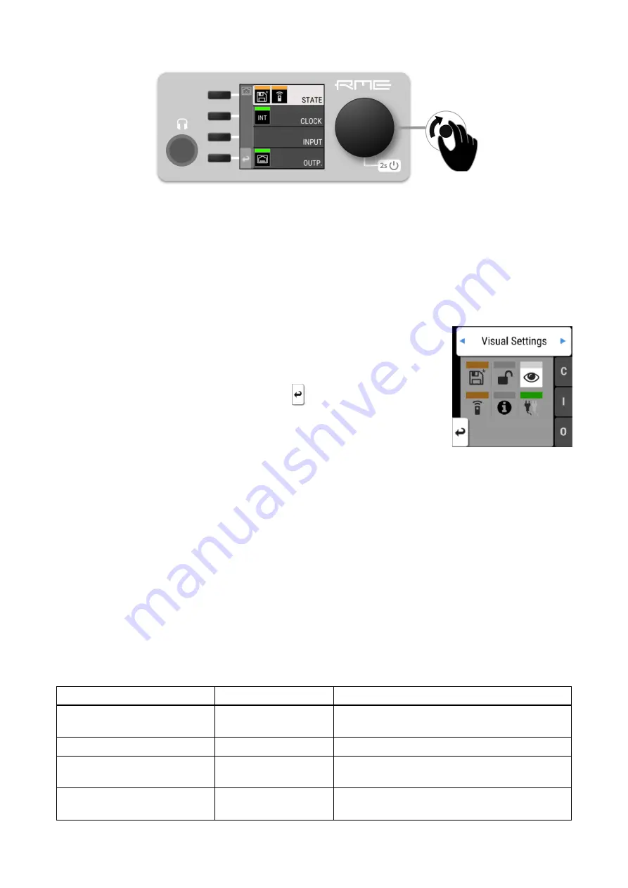
To access the INPUT section:

1. Push the encoder to open the menu

2. Rotate the encoder to highlight the "INPUT" section

3. Push the encoder to open the "INPUT" section.

2.3.2. Tabs

The 

STATE

INPUT

 and 

OUTPUT

 sections are further divided into 

tabs

,

which are shown when the section is opened. Upon opening one of these
sections, a cursor is shown to navigate between tabs and settings.

To leave a tab or the section, use the return key 

.

Tabs can generate a 

warning

 whenever a configured signal path cannot be established. This is then

indicated on the main screen as a red highlight of the corresponding section and in the main menu.
Warnings occur for example when a clock reference signal does not match the internal sample rate. They
also cause the standby LED to flash in white and red.

Tabs in the main menu can also show a 'caution notification', for example if loaded preset was not
saved. To see these notifications, open the main menu by pushing the encoder.

2.4. Status Indicator Color Chart

Notifications on this device have been optimized for different screen sizes. They are unified across the
device display and the web remote and include a color bar that indicates the current state at a glance.

The following table shows the possible status indicator colors for reference.

Status

Color

Description

Warning

red

Requires a configuration change or matching
external signal.

Notice

yellow

There is a potential issue.

Notice (in progress)

yellow with dots

There is a temporary issue that should resolve
automatically.

No Routing

light green

In output section:

 Output is sending an empty

signal.

RME 12Mic User’s Guide

5

 | 2.4. Status Indicator Color Chart

Содержание 12Mic

Страница 1: ...12V 2 5A Microphone Preamp User s Guide 12Mic 12 Channel digitally controlled Microphone Preamplifier with AVB and MADI...

Страница 2: ...RME 12Mic User s Guide...

Страница 3: ...ference 11 3 10 Control Section 12 3 11 Headphone Output 13 3 11 1 Analog Output Specifications 13 3 12 Power supply 14 3 13 MADI Coaxial and SFP 15 3 14 Network Connection 16 3 15 Word Clock 16 3 16...

Страница 4: ...6 Inverting the Phase of an Analog Input Signal 43 9 1 7 Gain Groups 43 9 1 8 Creating a Gain Group 44 9 1 9 Saving a Gain Group 45 9 1 10 Monitor Analog Inputs at Phones Output 45 9 2 MADI Input 46 9...

Страница 5: ...11 3 2 Number of Channels 57 11 3 3 Selecting a Sample Rate 58 11 3 4 Effects of Sample Rate Changes on Existing Routing 58 11 4 Set Word Clock Output to Single Speed 58 12 Annex 60 Glossary 61 CE Co...

Страница 6: ...ce Do not use this product near water i e swimming pool bathtub or wet basement Danger of condensation inside do not turn on before the device has reached room temperature ENSURE PROPER VENTILATION Do...

Страница 7: ...with lowest latencies In addition three optical ADAT outputs for up to 24 outputs at single speed for example a combination of microphone inputs MADI signals and AVB signals or 12 outputs at 96 kHz s...

Страница 8: ...1 Connect the device by USB or network cable and open the Web Remote See Section 8 4 1 Finding the Device on a Network 2 Download the current firmware from the RME website 3 Unpack the compressed fil...

Страница 9: ...menu It also controls the gain of the headphone output if turned and puts the device into standby mode if pushed for several seconds 2 3 1 Sections The main menu separates all controls into one of fou...

Страница 10: ...They also cause the standby LED to flash in white and red Tabs in the main menu can also show a caution notification for example if loaded preset was not saved To see these notifications open the main...

Страница 11: ...light green On standby screen in output section Output is working but issues with input Good green Everything is working as expected Inactive grey Feature is not monitored or disabled RME 12Mic User...

Страница 12: ...tput Section 3 4 Standby Switch Section 3 14 Network Connection Section 3 14 Network Connection Section 3 16 USB 2 0 Type B Jack Section 3 13 MADI Coaxial and SFP Section 3 15 Word Clock Section 3 17...

Страница 13: ...ic has a power switch at the AC inlet and a standby switch at the front Perform the following steps to power on the 12Mic 1 Ensure that one of the power inlets is properly connected to a power source...

Страница 14: ...pushed 3 5 Standby Indicator The following illumination patterns are possible No illumination There is no power at either of the two power inlets The power switch at the rear of the device is set to O...

Страница 15: ...to connect pin 3 negative cold to pin 1 ground to avoid noise from the unconnected pin 3 input 3 6 1 Analog Input Specifications XLR In 1 12 Input XLR electronically balanced Input impedance 3 4 kOhm...

Страница 16: ...ff frequency If the 12Mic is used for scientific research ultrasonic signals with measurement microphones that maintain a linear frequency response above 25 kHz please contact your support for a solut...

Страница 17: ...be configured completely at the device To do so the a TFT display shows a menu The adjacent encoder knob and buttons are used to navigate and change settings In addition each input channel has a dedi...

Страница 18: ...ed 3 11 1 Analog Output Specifications Phones 1 2 Resolution 24 Bit Noise DR 115 dB RMS unweighted 118 dBA Frequency response 44 1 kHz 0 5 dB 9 Hz 22 kHz Frequency response 96 kHz 0 5 dB 9 Hz 45 kHz F...

Страница 19: ...connected instead of or in addition to the internal power supply Redundancy is established when both inlets are connected to a power source Additionally both inlets are internally monitored The 12Mic...

Страница 20: ...ot plugging Any plugged in connector must be removed before unlocking the SFP Unlock and remove by pulling its integrated wire latch outward The wire latch of the SFP module is color coded Black stand...

Страница 21: ...audio streams when connected to AVB switches and endpoints remote status control with AVDECC and remote status control with HTTP over IP routed networks The current link state is also shown on the di...

Страница 22: ...resent or has a different sample rate than the chosen one 3 16 USB 2 0 Type B Jack The USB jack at the rear of the 12Mic provides an alternative connection method for web remote control when a network...

Страница 23: ...If preset 1 was changed manually the routing can be re created manually The factory preset does not route any signal to ADAT outputs 3 18 Mounting the Rack Adapter Brackets When the device should be...

Страница 24: ...fers optional accessories for the 12Mic Part Number Description SFP Modules MADI SFP MM MADI optical multi mode module 2 km LC MADI SFP SM MADI optical single mode module 20 km LC RME 12Mic User s Gui...

Страница 25: ...ontrol on the device and its web remote can be used to configure additional options An AVDECC controller can optionally acquire the device This means that the 12Mic is no longer configurable by displa...

Страница 26: ...audio channels at a fixed sample rate The stream port of the talker and the listener must be configured to have the same amount of channels and stream format Once a stream is connected each AVB switch...

Страница 27: ...fset of 2 ms adjustable down to 0 3 ms and as a listener where the latency is configured by the talker In AVB networks the latency is always specified by the talker and guaranteed by the listener This...

Страница 28: ...ignals to the Outputs 2 In the CLOCK section choose a sample rate and verify that the device is clock master or that the chosen clock source is in sync 3 After connecting an analog signal adjust its g...

Страница 29: ...any case warranty does not cover damage caused by improper installation or maltreatment replacement or repair in such cases can only be carried out at the owner s expense No warranty service is provid...

Страница 30: ...upport assistance Europe Audio AG Germany support rme audio de Synthax U K info synthax co uk Asia Australia RME Trading Ltd Hong Kong support rme trading hk Americas Synthax Inc U S A tech support sy...

Страница 31: ...fteen states in presets numbered 1 15 After a preset is loaded any change in the configuration will result in an unsaved changes state Representation of an unsaved preset on the device The internal pr...

Страница 32: ...e 2 Rotate the encoder to choose a preset 3 Select Load to load the preset 8 1 3 Loading Factory Default Settings The factory default settings are saved internally as Factory Preset and cannot be over...

Страница 33: ...r 3 optional Activate the Auto Lock toggle to lock after one minute 4 optional Select Lock Device Now to lock immediately Remember or write down the code shown in SET CODE It is not possible to unlock...

Страница 34: ...not required To turn off illumination on the device 1 Open the visual feedback tab in the STATE section 2 Change any of the following a Display to off to turn off the display b Status indicator to off...

Страница 35: ...web remote Clipping is detected when three consecutive samples reach digital full scale 0 dBFS The duration of how long the maximum level or clipping is shown can be manually changed to either five s...

Страница 36: ...can be visually inspected to ensure that signals are properly connected and routed Level meters are included for each port in the corresponding input and output sections but they can also be inspected...

Страница 37: ...emote The web remote control works on any IP based network including wireless networks The ethernet connection additionally supports AVDECC 1722 1 remote protocol which requires a physical connection...

Страница 38: ...ce name should be written as hyphens when entering the URL The device name is stored in a preset Loading a preset can therefore change the device name and require a different address 8 4 2 Web Remote...

Страница 39: ...tely Section 8 6 Power State Section 8 1 Presets Section 8 3 Front Panel Illumination Section 10 1 Routing Signals to the Outputs Section 11 CLOCK Section Section 9 INPUT Section Section 9 1 Analog In...

Страница 40: ...of the two power inlets receive power Its icon is a realtime representation of the current power state with an inactive power supply shown in grey The AC input corresponds to the left icon the DC inp...

Страница 41: ...ay the S state indicator will turn red In the main menu a warning is signaled as an icon with a red bar Power loss at DC input To activate the warning on the device 1 Open the power tab in the STATE s...

Страница 42: ...input stage only switch on phantom power after connecting a compatible condenser microphone or accessory Remember to switch off phantom power when unplugging a microphone and before saving a preset Th...

Страница 43: ...ADAT port 1 8 channels and port 2 4 channels RME 12Mic User s Guide 9 1 Analog Inputs 38...

Страница 44: ...nnel controls Monitor to phones Gain Groups and Phase Phantom Power XLR TRS Toggle Current Input Level Current Gain Encoder 9 1 2 Adjusting the Input Gain To adjust the input gain on the device 1 Pres...

Страница 45: ...to the input channels change to off no phantom power or yellow phantom power active 2 While holding down the button press the channel buttons next to each input where the phantom power should be togg...

Страница 46: ...vel meters press and hold the second button next to the X T indicator An instruction is shown on the display and the LEDs next to the input channels change to off XLR or white TRS 2 While holding down...

Страница 47: ...the TRS input channels change to white low impedance or blue high impedance 2 While holding down the button press the channel buttons next to each TRS input where high impedance should be activated A...

Страница 48: ...evel of two or more channels can be linked temporarily or permanently When part of a group gain is increased or decreased as an offset in dB to the previously set individual gain levels The offset is...

Страница 49: ...main screen 1 Press and hold the first button at the first input The channel is selected as the first channel in a group 2 While holding down the first button press a second button at another input A...

Страница 50: ...nt 9 1 10 Monitor Analog Inputs at Phones Output The phones output at the front of the 12Mic can receive any input signal Permanent routings are configured in the Phones Output settings see Section 10...

Страница 51: ...I at High Sample Rates The MADI standard AES10 allows transport of audio at sample rates beyond 48 kHz by reducing the number of available channels Double speed 88 2 kHz 96 kHz Double speed audio sign...

Страница 52: ...edundancy can be re established For a seamless failover the two MADI signals must be identical However only the SYNC and LOCK states are evaluated to confirm the current input state It is therefore po...

Страница 53: ...AVB streams can have a size of 1 8 12 or 16 channels in AM824 and AAF stream formats or 0 channels in CRF Media Clock stream format To change the amount of channels and format of incoming AVB streams...

Страница 54: ...inspection and configuration of outgoing signals including routing in four channel blocks 10 1 Routing Signals to the Outputs Each output channel of the 12Mic can receive any input signal If preset 1...

Страница 55: ...ily routed to the phones output while the original routing remains saved A button on the standby screen gives access to all features of the output The analog output level meters show the routed input...

Страница 56: ...ine level output This may for example be useful when an active talkback speaker with symmetrical input is connected to the 12Mic To toggle balanced output mode on the Phones output 1 On the main scree...

Страница 57: ...is also referred to as a daisy chain The output of the first device is connected to the input of the second device the output of the second device to the input of third device and so on until the sign...

Страница 58: ...ms are monitored by the device as follows Description Indicator Possible solution Disabled grey Create routing Disabled orange Create connection with AVDECC controller Streaming Transmitting green SR...

Страница 59: ...e always active On a new device with preset 1 loaded and not modified the analog input channels 1 8 are sent to ADAT port 1 and channels 9 12 are sent to ADAT port 2 The routing to ADAT outputs is sav...

Страница 60: ...and each of the four AVB streams can be chosen as clock reference This activates SteadyClock FS a technology that extracts a low jitter clock signal from the incoming signal Intelligent Clock Control...

Страница 61: ...anges This is called Intelligent Clock Control ICC It also handles deriving a sample rate of double or quad speed based on an incoming rate Intelligent Clock Control ICC Input Clock at input Selected...

Страница 62: ...mple rate than the current sample rate because two devices could choose different edges of the incoming clock signal ICC does not affect outgoing AVB streams Outgoing AVB streams will always correspon...

Страница 63: ...e mode can reduce the number of input and output channels available for routing This does not alter the routing table Any existing routing is hidden until another change of sample rate re enables the...

Страница 64: ...1 Open the CLOCK section see Section 2 3 Controlling the device 2 Use the third button to toggle WCL 1x RME 12Mic User s Guide 59 11 4 Set Word Clock Output to Single Speed...

Страница 65: ...Control and Digiface are trademarks of RME Intelligent Audio Solutions Microsoft Windows Windows 7 8 10 are registered trademarks of Microsoft Corp Apple and macOS are registered trademarks of Apple...

Страница 66: ...ne or more listeners AVB listener An AVB endpoint that receives an audio stream from a talker DHCP server A DHCP Server hands out IP addresses to network devices Every consumer oriented WiFi Router ha...

Страница 67: ...ee that interference will not occur in a particular installation If this equipment does cause harmful interference to radio or television reception which can be determined by turning the equipment off...

Отзывы: