background image

82  Using Dual View mode   

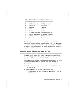
Table 10.  Using several display devices

C = Coprocessor mode only
E = No Expansion
I  = No Hardware Icon
O = No Overlay
R = Same Refresh rate

Software cursor is used while two controller and hardware 
icons are activated.

The same CRT controller can not be used for both LCD and 
TV.

Basically, the program should be started in the primary 
monitor, then you can drag the program to the secondary 
monitor to use. But, some programs are not able to drag from 
the primary monitor to secondary monitor.

The order of Icons on the Windows desktop could be changed 
after using Dual View mode.

Primary 
CRTC

Limits

Secondary 
CRTC

Limits

LCD

CRT

C, I, O

LCD

TV

C, I, O

CRT

LCD

C, E, I, O

CRT

TV

C, I, O

Two Displays

TV

LCD

C, E, I, O

TV

CRT

C, I, O

LCD + CRT

R

CRT + TV

R

LCD

CRT + TV

C, I, O, R

Three Displays

TV

LCD + CRT C, E, I, O, R

LCD + CRT

R

TV

C, I, O

CRT + TV

R

LCD

C, E, I, O

Содержание VM7000

Страница 1: ... warning indicates the possibility of personal injury Keys that you need to press to perform certain functions are shown in the manual enclosed in angle brackets For example Ctrl indicates the control key Ctrl on the computer s keyboard If you need to press two keys at the same time the key names are shown joined by a plus sign For example Fn F11 means that you should press the Fn key and hold it ...

Страница 2: ...User Documentation Your computer shipped from the factory with several software programs installed The software may include its own online or printed documentation Refer to the documentation or the Help options in the software for more information ...

Страница 3: ...computer Figure 1 through 3 show you the features of your computer Docking Station port Modem port TV out port IrDA is optional so that your computer may not have those optional ports or functions Figure 1 Front View of Computer Cover latch LCD Power button Fan vent Headphone jack Touchpad Speaker Status lights Floppy drive Microphone External mic jack CD ROM drive Modem jack Speaker Mouse Buttons...

Страница 4: ... Bottom View of Computer Parallel port Docking connector PS 2 mouse and keyboard port Video port Serial port Hard drive compartment Power Connector PC Card compartment Battery compartment TV out Memory module compartment System label Business card holder Flex Bay latch ...

Страница 5: ...g the power cord to the computer and to an electrical outlet All batteries lose their charge if they sit unused for an extended time period When not used battery can discharge fully in 2 to 3 months The battery may have discharged in the time it took for the computer to go from the factory to you To attach the power cord 1 Plug the AC adapter into the power connector on the back side of the comput...

Страница 6: ...5 hours When the battery is charging the battery charge light is amber When the battery is fully charged the light turns green See Using the Battery on page 33 for more information on using your computer s battery Turning On the Computer To turn on the computer s power for the first time 1 Push to the right and hold the cover latches on the front of the cover 2 Lift up the cover 3 Press and then r...

Страница 7: ...enter for assistance See Troubleshooting on page 99 Adjusting the LCD Display You may wish to adjust the LCD Liquid Crystal Display when you begin using your computer A TFT Thin Film Transistor LCD does not require adjustment for contrast because the contrast is set to remain at maximum To adjust the LCD Press Fn Right Arrow to increase the display brightness Press Fn Left Arrow to decrease the di...

Страница 8: ...operties in Control Pannel 2 Select the operations of power button Standby mode operates as Power On Suspend mode See Rest Mode on page 64 for more information Hibernate mode operates as Save To Disk mode Set Hibernate submenu to enabled to use Hibernate mode See Rest Mode on page 64 for more information In ACPI mode if you want to power off the system by the power button press and hold the power ...

Страница 9: ... disassemble your computer Opening the system chassis voids your warranty Only an authorised manufacturer service center can replace or add any parts inside the chassis Follow all the instructions and cautions in your computer user documentation The LCD has a polarized surface and can be damaged easily To prevent damage avoid touching the screen Use only approved AC adapters auto adapters memory m...

Страница 10: ...l with the floor Avoid bending or twisting your wrists as you work Your hands should float slightly above the keyboard Refer to a book on office ergonomics for more information on setting up your work area Take frequent breaks from working at the computer to rest your eyes and stretch your muscles Remember to save your data files frequently and to make backup copies of your files Traveling with Yo...

Страница 11: ...ay before trying to use it Sweet liquids leave a sticky residue that may jam the keyboard despite your efforts to dry it If you spill liquid on the LCD panel clean it immediately with a soft cloth and denatured alcohol Do not use water window cleaner acetone aromatic solvent or dry rough towels to clean it Some liquids damage the polarized LCD screen If your screen is damaged contact your authoriz...

Страница 12: ...ed Alphanumeric typewriter keys are arranged like a standard typewriter keyboard and are used for text entry The Windows keys on either side of the spacebar open Windows menus and perform other special functions Function keys when pressed together with the Fn key enable special functions Cursor and Screen control keys move the cursor They may perform other functions depending on your software Esc ...

Страница 13: ...s sign Figure 7 A number or symbol on the right corner of each keypad key shows its numeric function Figure 7 Numeric Keypad Press Num Lock to turn on the embedded numeric keypad The numeric functions of the keypad are enabled and the Num Lock light turns on See System Status Lights on page 18 for the location of the Num Lock light While the numeric functions are enabled you can temporarily return...

Страница 14: ...ner of your screen The gauge closes in a few seconds or you can press Esc to close the gauge See Monitoring the Battery Charge on page 36 for more information on the battery gauge Fn F7 KeyLock Locks the keyboard and activates password protection Type your password and press Enter to unlock the keyboard The Fn F7 key combination has no effect unless a password is enabled in System Setup The Num Lo...

Страница 15: ...porarily muted If you reinstall Windows install the internet launcher for volume control function keys on keyboard Fn F8 F9 F10 Or use the windows volume control on your screen Fn Right Arrow Brightness up Increases the LCD brightness Fn Left Arrow Brightness down Decreases the LCD brightness ...

Страница 16: ... Table 2 Using the Touchpad Mouse Action How To Move cursor Place your finger on the touchpad and slide your finger in the direction you want the cursor to move The faster you move your finger the faster the cursor moves across the screen Click Tap the touchpad once with your finger Double click Tap the touchpad twice with one finger Scroll up down Place your finger on the right hand side of the t...

Страница 17: ...standard mouse buttons For more information on these features and other features supported by your mouse driver see the Mouse properties in the Control Panel For information on attaching and using another pointing device or keyboard with your computer see Connecting Peripheral Devices on page 20 ...

Страница 18: ...of Light Power light Light is green when the computer s power is on Light blinks when the computer is in Power On Suspend mode See Rest Mode on page 64 for more information on Power On Suspend mode Num Lock light Light is on when the embedded numeric keypad is activated See Using the Embeded Numeric Keypad on page 13 for a description of the keypad Caps Lock light Light is on when the caps lock fu...

Страница 19: ... being accessed Do not turn your computer off when this light is on When the light is amber the floppy drive is being accessed When the light is green the hard drive is being accessed For a CD ROM or DVD ROM drive check the light on the drive itself to see if the drive is being accessed Battery charge light When the power cord is connected light gives information about the battery charge Light is ...

Страница 20: ...heral device with your computer turned on may seriously damage the device or your computer Figure 10 Peripheral Connectors Optional Table 4 shows the icons located near each connector and tells you the devices that you can attach to the connectors PS 2 mouse and keyboard port Video port Parallel port USB ports TV out port S VHS Modem jack Mic in jack Headphone jack Docking connector Power connecto...

Страница 21: ...ck Connect a telephone line to connect to internet or send receive faxes see the modem user s manual for more information Power connector Plug in the AC adapter to run the computer and charge the battery see Attaching the AC Adapter on page 5 PS 2 Personal System 2 mouse and keyboard port Connect a PS 2 compatible mouse or external keyboard or keypad to this port Make sure your computer is turned ...

Страница 22: ... such as a serial mouse into this 9 pin port If the device has a 25 pin connector you need a 25 to 9 pin serial adapter Video port Plug the interface cable of an external monitor into this 15 pin connector and then plug the monitor power cord into a grounded outlet TV out port plug a S VHS jack into this port and the other side of the jack into an external TV No audio is transmitted via this port ...

Страница 23: ...es and CD ROM drive is connected as a slave type of IDE devices If you want to install another IDE device to Flex Bay you must set the switch of a device to slave type See Using Options on page 88 for detailed information and the location of the switch on each devices Refer to the below table to set the switch on devices Table 5 Setting the IDE type To remove a device from the Flex Bay 1 Turn the ...

Страница 24: ...ex Bay 1 Turn the computer s power off 2 Place the device into the bay 3 Push the device in until it is flush with the chassis 4 Push down on the Flex Bay latch until the latch snaps into place Your computer s operating system automatically recognizes the device in the Flex Bay and configures your computer accordingly Flex Bay latch ...

Страница 25: ...om your floppy drive use high quality floppy disks To use a floppy disk in computer insert it into the floppy drive Figure 12 Figure 12 Inserting a Floppy Disk To remove a floppy disk press the eject button on the floppy drive The floppy drive light on the computer is on when the computer writes to or reads from a floppy disk Do not remove a disk when this light is on To protect the data on your f...

Страница 26: ...26 Using the Floppy Drive Do not write directly on a label on your disk instead write on a disk label first and attach the label to the disk Make copies of all your important disks ...

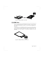
Страница 27: ...he CD ROM and push it until the tray ejects 2 Insert a CD compact disc label side up or remove a disc if you have finished using it 3 Push the tray in gently to close the drive tray Figure 13 A light on the drive tray is on when the computer is reading from a CD Do not remove a disc when this light is on Figure 13 Using the CD ROM Drive The name of the CD ROM drive is the letter following the lett...

Страница 28: ...ftware of your computer enable the computer to play audio compact discs If you wish to do so you can attach external speakers to the Headphone jack To play an audio compact disc 1 Insert a compact disc into your CD ROM drive a Press the button on the CD ROM drive and its tray slides out b Insert a CD label side up c Push the tray in to close the drive tray The CD Player button appears on the taskb...

Страница 29: ... CD Player Window 3 Click the Eject button on the CD Player window or press the button on your CD ROM drive The drive tray opens and you can remove the disc from the CD ROM drive 4 For more information on playing compact discs see the Help menu in the CD Player window Play Stop Eject ...

Страница 30: ...ining the ATI DVD Player MPEG 2 software is included with systems and options shipped with DVD ROM drives 1 Start Windows 98 and insert the CD Labelled DVD Player into the DVD ROM Drive 2 The Installation application will start automatically so follow the on screen instructions to complete the installation 3 Reboot the system 4 Make sure that DMA access is enabled for the DVD Drive a From Control ...

Страница 31: ...or want to erase all data on your existing hard drive refer to the manual for your operating system Windows 98 can work with FAT 16 or FAT 32 a 32 bit file allocation table your computer has been supplied with FAT 32 Older software that you may have 16 bit software may require FAT 16 to run Similarly Windows NT 4 0 can use FAT 16 or NTFS the Windows NT file system There are utilities included with...

Страница 32: ...the old hard drive from the computer as described in the previous section 2 Slide the new drive into the hard drive compartment Make sure the drive is pushed back as far as it will go 3 Install the screw that holds the hard drive in place 4 If you intend to use save to disk mode see Creating a Save to Disk Partition on page 67 5 Format your drive and reinstall your files See the Operating System a...

Страница 33: ...s charging normally the battery charge light on the computer is amber See System Status Lights on page 18 for the location of the battery charge light When the battery is fully charged the light changes to green When you use a new battery pack for the first time or use a battery after a long period of storage the initial battery life is shorter than normal Normal battery life resumes after a few d...

Страница 34: ...omputer s rechargeable battery may be considered hazardous waste If you replace your battery with a new one Keep the old battery out of the reach of children Dispose of the old battery promptly Make sure that you follow all local requirements when you dispose of the old battery Removing the Battery Your computer comes with the battery pack inserted in the computer To remove the battery from the co...

Страница 35: ...he computer over so the bottom of the unit faces up 2 Slide the battery compartment cover straight up and off the computer Figure 17 Insert the battery into the battery compartment ensuring the correct orientation so that the battery fits in its slot properly 3 Slide the battery pack into the compartment Make sure the battery is fully inserted into the compartment 4 Align the tabs on the battery c...

Страница 36: ... approximately 3 2 5hrs for Ni MH hours Battery life estimates are subject to variation The actual life of your battery may be less than the estimates given in the manual You can monitor the charge of the battery pack installed in your computer through the battery gauge Using the Battery Gauge Press Fn F6 to display the battery gauge on the LCD Figure 18 You can display the battery gauge while you...

Страница 37: ...options for computers shipped with Windows NT installed To use PowerProfiler to monitor the battery charge place the cursor on the battery icon in the right corner of the taskbar PowerProfiler shows you the amount of battery charge remaining The color of the battery icon also indicates approximate battery charge Green Charge is adequate to power computer Yellow Charge is low Red Charge is very low...

Страница 38: ...lem may be that The battery temperature is below 41 F 5 C or over 95 F 35 C If you think the battery temperature is too hot or too cold turn off the computer remove the battery and let the battery reach room temperature Then try charging the battery again The battery is defective Replace the battery with a new battery Warnings Condition Action to Take The computer beeps 5 times low pitched beeps B...

Страница 39: ...in your computer Modems are factory installed and are not user installable SENS Modem Naming Convention SENS Modem Name is determined by the following rule SENS MM NN P X W Modem 1 2 3 4 5 1 MM Chipset Vendor LT Lucent Technologies RW Rockwell Now Conexant PT PCtel CX Conexant Old Rockwell 2 NN Maximum Speed 56 56K 336 33 6K 3 P Interface P PCI Interface M Mini PCI Interface A AMR MDC Interface I ...

Страница 40: ...the digital key phone line the modem will be damaged If you use the modem on a PBX system Analog Key phone system If you use a simple terminal program you should type ATX3 W or ATX3 command as an initialization command If you use a Windows Communication Program Follow the instructions below 1 Click the Start button and then point to Settings 2 Click Control Panel 3 Double click Modems icon and the...

Страница 41: ...ve fine points of operation between different vendor s modems and unusual telephone line conditions 1 Due to FCC limitations speeds of 53kbps are the maximum permissible transmit power levels during download transmissions Actual data speeds will vary depending on line conditions 2 In order to use the 56K feature be sure to check if the standards supported by the on line service provider and the mo...

Страница 42: ... 2 1 PPMI 1 0 support Installing the Modem Driver in Windows 95 98 You can install the modem driver as shown in the following The figures illustrated in this manual may not be identical to those on your system Install the Modem Driver Before you install the modem drivers check if the PCI Card under Other devices of Device Manager tab of Control Panel on Windows exists If it exists remove it first ...

Страница 43: ... use the modem If your modem only supports Domestic you must select the country where you bought your notebook computer And if you use the modem in other countries your modem may not work properly If your modem supports Worldwide please check with your local distributor which countries can be supported by the SENS modem 1 Click the Start button point to Settings and the click Control Panel 2 Doubl...

Страница 44: ... command into any communications program like Hyper terminal You can do the below jobs more easily by using AT commands Calling up or hanging up the phone in order to communicate by Computer modem Choosing a modem in order to make the most efficient communication status But as the communication programs are becoming more efficient and more intelligent nowadays users do not have to know all the AT ...

Страница 45: ... command mode again Using Command Mode during Communications Sometimes you have to use AT command while you re communicating with others via modem In this case you can use command for AT command without hanging up your telephone Pressing three times makes fax modem change to command mode Of course the telephone is not disconnected Don t enter Enter key after input Connection may be lost depending ...

Страница 46: ...Press Enter and the model dials to 123 4567 Display the result value After entering AT commands the result value is displayed on the screen The result value can be displayed during communication Generally the result will be OK According to the ATV command the result can be displayed as Words or numeral letters ATV0 Display as numeral letters ATV1 Display as English words ...

Страница 47: ...me as hang up H1 Off Hook same as hold on ATLn Modem speaker loudness control L0 1 Low volume L2 Medium volume L3 High volume ATMn Modem speaker control M0 Disables modem speaker M1 Enables only when in connection procedure M2 Enables always M3 Enables until carrier has been detected after connection ATS0 n Sets S0 register value n range 0 255 Sets the number of incoming ring signals before answer...

Страница 48: ...ng in modem memory n 0 3 x phone number e g AT Z0 1235678 Automatically calls the stored phone number by using the following command ATDTS0 Recalls the stored phone number as AT Z0 by tone dial ATDPS0 Recalls the stored phone number as AT Z0 by pulse dial AT MS X Sets protocol for modem connection X V90 V34 AT MS V90 default setting Try to connect with V90 max 56 Kbps AT MS V34 Try to connect with...

Страница 49: ...clude all the fields listed here or may include additional fields Field names and order of appearance can vary according to the version of the BIOS basic input output system on your computer You can use the configuration listing at the back of this manual to record information specific to your computer See Recording the Computer Hardware Configuration on page 113 Fill it out as you complete your S...

Страница 50: ...ent menu Left Arrow and Right Arrow keys Keypad arrow keys Select a different menu Pressing ESC at the Main menu brings you to the Exit menu Up Arrow and Down Arrow keys Keypad arrow keys Move the cursor up and down between fields Tab Moves the cursor forward through the cells for a highlighted field If the field has only one cell the Tab key moves the cursor down to the next field Tab Shift Moves...

Страница 51: ...nd to go to the last page To exit the help window press Enter or Esc If your computer will not boot after you have changed settings in System Setup and exited the program reboot and press F2 to reenter System Setup Once in System Setup you can try to change the values that caused your computer boot to fail If the problem persists press F9 to load the default values Main Menu When you open System S...

Страница 52: ...enu Manually set the other fields in this submenu only if the drive you have installed in your computer is not recognized by System Setup Set the Auto option of the Type field in the Secondary Master submenu to enable the system to boot from Bootable CD ROMs you will also need to check the boot device priority field and Bootable CD check field After you make your selections from this submenu press...

Страница 53: ...ransfer Mode Selects the method for transferring data between the hard drive and system memory Refer to your drive s user documentation to specify the correct option for this field Options are Standard Fast PIO 1 Fast PIO 2 Fast PIO 3 Fast PIO 4 FPIO3 DMA1 and FPIO4 DMA2 Ultra DMA Mode Enables the hard drive to use ultra DMA direct memory access transfer mode to transfer data between the drive and...

Страница 54: ...ave both built in and external displays used as the dafault If you select CRT and no external monitor is attached you will see no display until you attach the external monitor The default is LCD I O Device Configuration Opens the I O Device Configuration submenu if you press Enter when this field is highlighted If you attempt to set two ports to the same settings the fields will be marked with ast...

Страница 55: ...default or Disabled When the Floppy disk controller field is set to Enabled the computer s operating system uses the default configuration for the controller Local Bus IDE adapter Enables the integrated IDE local bus adapters Options are Enabled default and Disabled Large Disk Access Mode Enables your computer s operating system to work with drives larger than 540 MB Choose DOS default for Microso...

Страница 56: ... have access to floppy drives If the field is set to Supervisor and a user password is enabled the user must enter the supervisor password in order to boot from the floppy drive Power Menu The Power menu of System Setup allows you to enable and adjust your computer s sophisticated power saving features Enabling these features extends the life of the battery If your computer shipped with Windows 98...

Страница 57: ...he save to disk mode all system logic except for your computer wakeup circuitry and battery charger is turned off During save to disk mode the system and video memory are saved to the hard drive and are restored when your computer resumes from rest When the computer enters save to disk mode it will not resume normal operation at a specified time no matter how the Resume On Time field is set Hard D...

Страница 58: ...ays the system configuration when the computer starts The options are Enabled and Disabled default Boot Device Priority Enables you to select the order in which the computer attempts to boot from different devices The field has three options Diskette Drive Removable Devices Hard Drive and DVD CD ROM To choose a device as the first second or third boot device 1 Press Enter at the Boot Device Priori...

Страница 59: ...ut saving your changes When you select this item and press Enter a message appears asking you if you want to save changes before exiting Choose No and press Enter to exit without saving changes Choose Yes and press Enter to save changes and exit Load Setup Defaults Loads the default values for all System Setup parameters When you select this option and press Enter a message appears asking if you w...

Страница 60: ...omputer such as in a network environment a supervisor password can prevent unauthorized access to certain security options Choose the type of password security that is appropriate for your work If you want to set a user password you must set a supervisor password first Creating a Password To create a password 1 At startup press F2 to open System Setup 2 Use the Right Arrow key to select the Securi...

Страница 61: ... open System Setup 2 Type your password when prompted and press Enter 3 Use the Right Arrow key to select the Security menu 4 Use the Down Arrow key to select Set Supervisor Password or Set User Password 5 Press Enter The computer prompts you to enter the current password 6 Press Enter The computer prompts you to enter a password Do not type anything 7 Press Enter The computer prompts you to re en...

Страница 62: ...up For more information about the Fixed disk boot sector field see Security Menu on page 55 Locking the Floppy Drive If you have an supervisor password you can lock the floppy drive so that a user with only a user password cannot load personal software which may introduce a virus into the computer To enable the floppy lock select the option Supervisor in the Diskette access field in System Setup F...

Страница 63: ...in System Setup have no effect on Windows 98 Battery low and battery very low warnings are configured using the Power Management option If you want to use Hibernation function in ACPI mode Windows 98 then click Start Settings Control Panel and double click Power Management icon Select Hibernate on the When I press the sleep button on my computer field in Advanced tap Then you can use the power but...

Страница 64: ...mode to standby mode in system setup If you enable both standby and rest modes your computer enters standby when the delay time you chose for standby has elapsed and then enters rest mode when the delay time you chose for rest mode has elapsed Rest Mode The Rest Timeout field in System Setup enables you to specify the time period the computer can remain idle no user input or device activity before...

Страница 65: ...autions Observe the following precautions when using rest mode Save all open files before you press Fn F11 to manually place your computer into Rest mode If you purchased a new hard drive make sure that you create a save to disk partition equal to the amount of system memory plus the amount of video memory plus 2 MB before you enable save to disk mode See Creating a Save to Disk Partition on page ...

Страница 66: ...ep the following in mind when using PowerProfiler If you disable power management in PowerProfiler the setting overrides any power management settings in System Setup If you enable LCD and hard drive timeouts in PowerProfiler and the standby timeout in System Setup the LCD and hard drive turn off when the shortest timeout period in either program passes If you disable the Resume on Time field in S...

Страница 67: ...ore you set partition and format HDD set Fixed Disk Boot Sector to Normal in Security menu of System setup To create FDISK 1 Set the system boot with CD ROM press F8 key to boot with Safe mode command prompt only 2 Operate Fdisk exe type A fdisk and press Enter 3 When Do you wish to enable large disk support Y N shows select Y and press Enter 4 Select 1 Create DOS partition or Logical DOS Drive fi...

Страница 68: ...s calculated as below formula and it could be different according to system memory 143360 system memory 64MB video memory 8MB extended memory 64MB buffer space 1MB x1024 4 Press any key to restart the system To format the HDD 1 Boot system by CD ROM 2 Operate Format exe type A format c s and press Enter 3 Warning message saying all the data will be removed shows type Y for Proceed with Format Y N ...

Страница 69: ...ons and drivers Under the Boot menu in System Setup set Diskette Drive as the first boot device and CD ROM Drive as the second see Using System Setup on page 49 for information on setting options See the documentation that accompanied your operating system for detailed information on installation and setup To re install your operating system Windows 98 1 Turn off the computer and insert your CD RO...

Страница 70: ...12 Follow the prompts to install your operating system Windows NT 4 0 Workstation 1 Repeat steps 1 2 2 Follow the prompts The installation program will partition and format your hard drive as necessary see the documentation that accompanied your operating system for more information on installation and setup To re install your original applications and drivers 1 Start your computer and wait for th...

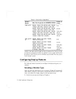
Страница 71: ...layed on the entire screen In general the more pixels the LCD can display the better the image Your LCD screen is XGA SVGA with a maximum display of 1024x768 800x600 about 800 000 480 000 pixels The number of colors the LCD can display is measured by how many bits the LCD uses to represent each pixel 8 bit color can support 256 different colors 16 bit color can support 64 K 65 536 colors 24 bit co...

Страница 72: ... you can adjust the display settings by selecting a monitor type 1 Click the Start button on the Windows 98 taskbar Software Drivers Resolution Supported with 4MB 8MB SGRAM Number of Colors Windows 98 640x480 720x480 800x600 848x480 1024x768 1152x864 1280x1024 1400x1050 1600x1200 256 640x480 720x480 800x600 848x480 1024x768 1152x864 1280x1024 1400x1050 1600x1200 65 536 640x480 720x480 800x600 848x...

Страница 73: ...ct the Show all hardware radio button 12 Select a manufacturer and model setting that matches your external monitor Your computer has an intelligent video chip set that automatically matches your LCD panel resolution and frequency when an external monitor is not present 13 Click the Next button 14 The Update Device Driver Wizard screen appears showing the driver location of the device you have sel...

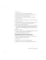
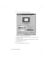
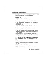
Страница 74: ...perties in Windows NT 4 0 6 To change the colour depth click the arrow next to Color palette and select the colour depth you want 7 To change the resolution click and drag the knob under the Screen area until you select the resolution you want 8 Click the OK button 9 Follow the prompts that appear on the screen ...

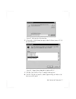
Страница 75: ...a specific location so you can select the driver you want Click the Next button 8 Click the Have disk button If the driver is on a floppy disk insert it into the floppy drive Click the Browse button and locate driver you want to install Click the OK button 9 Select the new driver in the Select Device screen and click the Ok button 10 Click the Next button to install the new driver and follow any d...

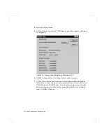
Страница 76: ... 0 6 Click the Change button The Change Display window appears 7 Click the Have disk button If the driver is on a floppy disk insert it into the floppy drive or if you want to use the origianl factory driver insert the Restore CD ROM into the CD ROM drive Enter the path to the directory where the drivers are located or click the Browse button and locate driver you want to install Click the OK butt...

Страница 77: ...lar to the following line appears under the Display option ATI 3D RAGE LT PRO PCI Figure 22 Change Display Dialog Box in Windows NT 4 0 9 Click OK The Third Party Drivers warning window appears 10 Click Yes The driver is copied A window appears telling you the driver has been successfully copied ...

Страница 78: ...yed No Audio is transmitted through the TV Out port To check if and how your TV displays the TV out signal see the documentation included with your TV Concurrent enabling LCD and TV doesn t support So either TV or LCD is recommended While TV is ON pressing Fn CRT LCD cause TV Out disable Then you should follow from step4 DOS mode you should restart To enable TV out 1 Connect the TV to the TV Out p...

Страница 79: ...em will now try to detect a TV connected to the TV out port 12 Put a tick in the box under the TV symbol If the TV symbol is greyed out then the system has not detected a TV check that the TV standard in the System Setup is set correctly and that the TV is turned on and connected properly 13 Click OK and follow the prompts that appear on the screen ...

Страница 80: ...s tab 4 Click the second monitor among two monitor pictures 5 When Do you want to enable this monitor message appears then select Yes 6 Click Apply or OK To confirm whether the system is set properly with Dual View mode 1 Open Display properties and click Settings tab 2 Place the mouse pointer on the first monitor picture and click over a second then digit number 1 will be shown on the first actua...

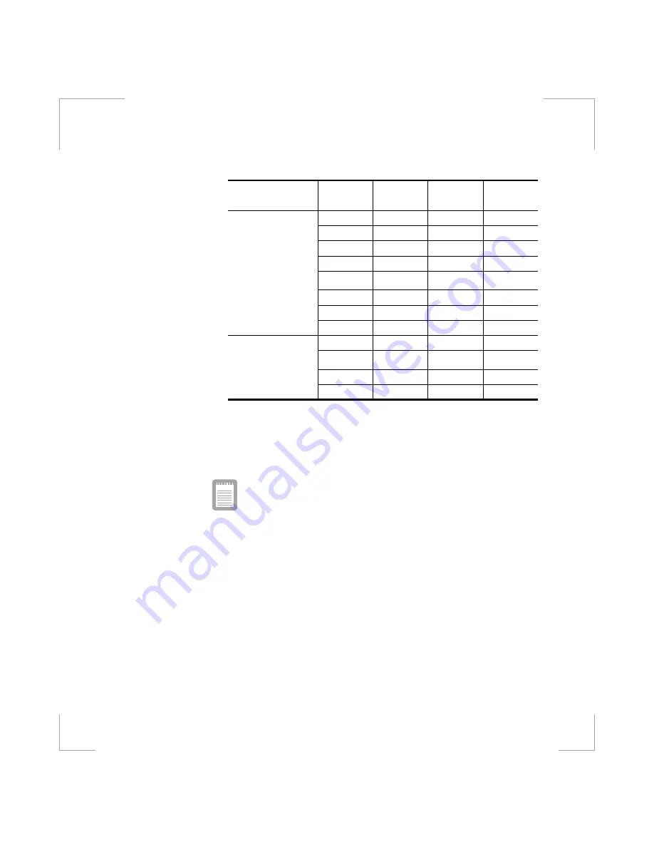
Страница 81: ...e Click Apply or OK Limits and cautions of using Dual View mode The supporting capabilities of the primary monitor and the secondary monitor are differ Primary CRT Controller Capabilities VGA Mode Accelerator Mode Hardware Overlay Hardware Cursor or Hardware Icon Ratiometric Expansion from up to 1024x768 source Secondary CRT Controller Capabilities No VGA Mode Accelerator Mode No Hardware Overlay ...

Страница 82: ...d be started in the primary monitor then you can drag the program to the secondary monitor to use But some programs are not able to drag from the primary monitor to secondary monitor The order of Icons on the Windows desktop could be changed after using Dual View mode Primary CRTC Limits Secondary CRTC Limits LCD CRT C I O LCD TV C I O CRT LCD C E I O CRT TV C I O Two Displays TV LCD C E I O TV CR...

Страница 83: ...o memory uses one memory pool for two screen and Direct Draw application on Dual View mode in Windows 98 So activating the Direct Draw application which does not support that mode could cause fail in changing mode 6 The program which does not have Dual View compatibility can not be used in the secondary monitor on Dual View mode 7 The ATI video driver supports VPE Microsoft video port specificatio...

Страница 84: ... PC Cards The SystemSoft CardWizard for Windows NT program provided with systems that ship from the factory with Windows NT installed also supports both 16 bit and 32 bit cards Zoomed video Both PC Card slots and the video chip on your computer support zoomed video When you install a zoom video PC Card in the upper or lower slot data can be transferred directly from the PC Card to video and audio ...

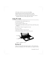
Страница 85: ... computer is on To insert a PC Card into a slot 1 Push the slot door in with the PC Card 2 Align the card with a slot and insert the card into the slot until it locks in place Figure 23 The eject button for the card slot operates in two steps To remove a PC Card 1 push the eject button once to pop it outward 2 Push the eject button again then the card will be ejected Figure 23 Inserting a PC Card ...

Страница 86: ... computer beeps twice If CardWizard cannot automatically configure your PC Card the computer beeps once and a message appears telling you that the card has not been configured Click the Wizard button on the CardWizard window CardWizard then analyzes why the card was not configured and fixes the problem or gives you information to help fix the problem CardWizard works with the PowerProfiler program...

Страница 87: ...ard program or you may lose data To stop and remove a PC Card from your computer 1 In the SystemSoft CardWizard screen click with the right mouse button on the name of the card you want to remove 2 Click Stop in the Actions menu A red stop sign appears on the main screen when the card is stopped 3 Click OK 4 Push the card eject button on the side of the PC Card slot 5 Pull the card out of the slot...

Страница 88: ...rive compartment or the Flex Bay A CD ROM drive module A DVD ROM drive module A ZIP drive module A Superdisk LS 120 drive Docking options that enable you to use your computer like a desktop computer The options that are available may change periodically Contact your reseller for updated information on current and new options AC Adapter The optional AC adapter operates in the same way as the adapte...

Страница 89: ...ions If you are in an automobile turn on the automobile s ignition to supply power to the adapter In some vehicles power to the cigarette lighter socket is always on and you do not need to turn on the ignition If the previous procedures do not activate the adapter you may need to change the fuse in the adapter To remove the fuse from the adapter unscrew the adapter cap with a pair of pliers and re...

Страница 90: ...the power cord and remove the battery Also disconnect any peripheral devices Before handling a memory module discharge any static electricity by touching a grounded surface or using a grounding wrist strap Do not insert objects with conductive material such as metal screwdrivers or graphite pencils into the memory module compartment Be careful in handling the metal plate of the memory door Install...

Страница 91: ...y When removing modules pull on the plastic portion of the connector slots tabs only Do not pull on the metal part of the tabs or you may damage the tabs a Pull the tabs on the connector slot outward slightly until the edge of the memory module pops up Figure 25 Figure 25 Removing a Memory Module b Hold the memory module by the edges and pull it forward out of the compartment 5 Align the connector...

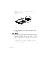
Страница 92: ...he memory integrity Hard Drives You can order optional hard drives for your system A hard drive can be installed in the hard drive compartment to replace your existing hard drive see Installing a Hard Drive on page 32 for information on installing a new drive in the hard drive compartment Or you can order a hard drive that fits in the Flex Bay in this case you should purchase the drive pack to fit...

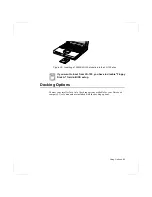
Страница 93: ...Drive on page 27 for directions on installing the CD ROM drive To install and use the CD ROM drive in the Flex Bay you must set the switch on a device to set it as slave type of IDE bus Set switch 1 to ON and switch 2 to ON See Using the Flex Bay on page 23 for information on installing a device in the Flex Bay Figure 28 Setting the switch on CD ROM drive ON 1 2 ON 1 2 ...

Страница 94: ...drive enables you to store 100 MB of data on a ZIP 100 diskette The ZIP drive fits in the Flex Bay see Using the Flex Bay on page 23 There is IOmega ZIP To install and use the ZIP drive in the Flex Bay you must set the switch on a device to set it as slave type of IDE bus Set switch 1 to ON and switch 2 to OFF See Using the Flex Bay on page 23 for information on installing a device in the Flex Bay...

Страница 95: ...nto the LS 120 drive If you want to boot from LS 120 you have to disable Floppy Disk A field in BIOS setup Docking Options Contact your reseller for a list of docking options available for your Notebook computer User s manuals are included with the docking options ...

Страница 96: ...RQ is a hardware line that a device can use to send signals to the microprocessor When the device needs the microprocessor s service the device sends an interrupt request signal to the microprocessor The number of IRQs available for any computer is limited by industry standards Because it ships with numerous features this computer uses most of the available IRQs If you add another device to your c...

Страница 97: ...s NT system you need to reinstall SP4 The version of SP3 on your computer s hard drive includes the correct video driver for your system If possible always install this version on your computer To install SP3 1 Run the executable file On your computer s hard drive this file is located at C SP4 i386 update 2 Follow the instructions on the screen with these exceptions a When you are prompted to over...

Страница 98: ... you do not overwrite the pcmcia sys file or you may be unable to use your computer After installation of Windows NT 4 0 install the latest service pack to support proper video PC card driver If you install SP4 from any source other than your computer s hard drive the video driver that was installed on your computer at the factory is overwritten After you install the service pack you must reinstal...

Страница 99: ...use system instability and incompatibility with some applications If your computer is not behaving as expected and no error messages appear disable the External Cache setting in the Memory Cache field of System Setup Nothing appears on the LCD panel when you turn on the computer Adjust the brightness on a TFT LCD Are you using an external monitor If so press Fn F5 to return to the LCD panel Nothin...

Страница 100: ...system unit does not work properly Check the attached device Is it turned on Is the cable properly installed between the device and the port If you are using an operating system that is not plug and play compliant make sure the Plug Play O S field in System Setup is set to No Check to make sure that the port is enabled in System Setup A PC Card does not work correctly Make sure that the PC Card is...

Страница 101: ...erminal for faster speed in transfering the file see Windows help to get information on its setting method You may hear the audio noise while using the ifrared port set Use Infrared port field in Control Panel Infrared to Disabled to prevent noise Modem Problems My modem doesn t connect to services or disconnects during communication If your modem has difficulty in connecting to on line services a...

Страница 102: ...the unnecessary messages or data you received by Modem or Fax every one to three months as required If you re using WWW of the internet many picture and data files can get downloaded to your HARD DISK every time you visit a home page which will consume a lot of your HARD DISK space Delete the unnecessary messages or data you received by Modem or Fax every one to three months as required For more d...

Страница 103: ...Depth 9 92 in 25 2 cm Weight 12 1 in with CD ROM drive without battery 4 85 lb 2200 g Weight 13 3 in with CD ROM drive without battery 5 73 lb 2605 3 g Environment Ambient temperature operating 50o 90o F 10o 32o C Ambient temperature storage 23o 104o F 5o 40o C Relative humidity noncondensing operating 20 80 Relative humidity noncondensing storage 5 90 Altitude operating 0 to 8 000 ft 0 to 2 348 m...

Страница 104: ...e with no power management enabled 3 0 hr Ni MH Dumb Battery Normal Weight 1 36 lb 620 g Nominal open circuit voltage 12 0 VDC Capacity typical 4000 mAhr 48whr Charging time approximate with computer turned off typical 2 0 hr Charging time approximate with computer turned on typical 4 0 hr Average battery life with no power management enabled 2 5 hr External AC Adapter Operating voltage 100 240 VA...

Страница 105: ... interface BBS Bulletin board system BIOS Basic input output system C Centigrade CD Compact disc CD ROM Compact disc read only memory cm Centimeters COM Communication as in communication port CMOS Complementary metal oxide semiconductor DC Direct current DMA Direct memory access DPMS Display power management signaling DRAM Dynamic random access memory DSTN Double layer super twist nematic ECP Exte...

Страница 106: ... display m Meters mA Milliampere mAhr Milliampere hour MB Megabyte mm millimeter MPEG Motion Picture Experts Group MPU Microprocessor unit ms Millisecond PDF Portable document format PC Personal computer PCI Peripheral component interconnect PCMCIA Personal Computer Memory Card International Association POST Power on self test PNP Plug and play PS 2 Personal System 2 RAM Random access memory ROM R...

Страница 107: ...Abbreviations 107 USB Universal serial bus V Volt VAC Voltage alternating current VCC Voltage collector current VDC Voltage direct current whr Watt hour ...

Страница 108: ...tem It enables the computer to communicate with the screen keyboard and other peripheral devices without using programs on the hard disk The BIOS on your computer is flash BIOS which means that it has been recorded on a flash memory chip that can be updated if needed Boot To start your computer A cold boot resets the entire computer and runs through all computer self tests A warm boot clears out c...

Страница 109: ...ation in CMOS memory is saved COM port COM stands for communication COM ports are the serial ports in your computer Compact Disc A compact disc CD Conventional memory The first 640 KB of system memory Operating systems and application programs can directly access this memory without using memory management software Disk The device used by the computer to store and retrieve information Disk can ref...

Страница 110: ...is important for a notebook computer I O Input output Refers to peripheral devices such as printers that are addressed through an I O address I O address I O stands for input output Peripheral devices such as printers are addressed through the I O port address IRQ interrupt request line The IRQ is a hardware line that a device uses to signal the microprocessor when the device needs the microproces...

Страница 111: ...memory cards PC slot The PC slot is the hardware slot in the computer where the PC Card is placed Pixel A pixel is an individual dot in a graphic displayed on your computer The pixels are so close together that they look as though they are connected An LCD screen displays thousands or millions of pixels Plug and Play A plug and play operating system automatically configures computer components to ...

Страница 112: ... the same as RAM Sector Also known as disk sector The portion of a track that is numbered and can hold a specified number of characters usually 512 KB Shadow RAM A write protected area of RAM that contains a copy of the BIOS As the computer boots the BIOS is copied from its permanent location in ROM to RAM The BIOS can be executed much faster in RAM than in ROM The BIOS remains in shadow RAM until...

Страница 113: ... IDE ADAPTER SUBMENU Primary Master Type __________Cylinders __________ Multi Sector Transfers _____ LBA Mode Control Enabled Disabled 32 Bit I O Enabled Disabled Transfer Mode Standard Fast PIO 1 Fast PIO 2 Fast PIO 3 Fast PIO 4 Ultra DMA Mode Mode 0 Mode 1 Mode 2 Disabled Primary Slave Type ___________ Cylinders __________ Multi Sector Transfers _________ LBA Mode Control Enabled Disabled 32 Bit...

Страница 114: ...BMENU Serial port Enabled Disabled Base I O Address 3F8 IRQ 4 2F8 IRQ 3 3E8 IRQ 4 2E8 IRQ 3 Infrared port Enabled Disabled Base I O Address 3F8 IRQ 4 2F8 IRQ 3 3E8 IRQ 4 2E8 IRQ 3 Mode FIR DMA Channel DMA 3 DMA 1 Parallel port Enabled Disabled Mode Output only Bi directional EPP ECP Base I O Address 378 IRQ7 378 IRQ 5 278 IRQ 7 278 IRQ 5 3BC IRQ 7 3BC IRQ 5 DMA Channel DMA 1 DMA 2 DMA 3 Floppy dis...

Страница 115: ... Timeout Off Time_________________ Rest Mode Power On Suspend Save To Disk Rest Timeout Off Time_________________ Harddisk Timeout Off Time_________________ Resume On Modem Ring On Off Resume On Time On Off Resume Time ________________________ BOOT MENU Logo Screen Display Enabled Disabled QuickBoot Mode Enabled Disabled Bootable CD Check Enabled Disabled Summary screen Enabled Disabled Boot Devic...

Отзывы: