Operating manual SYCON 2702
Analyzer for automated monitoring
of total hardness, residual hardness or carbonate hardness in process water
Страница 1: ...Operating manual SYCON 2702 Analyzer for automated monitoring of total hardness residual hardness or carbonate hardness in process water ...
Страница 2: ...th housing 15 Work on pressurised water lines 16 Operation with unpressurised sample water 17 Electrical installation 18 Connection of supply voltage 19 Connection of the relay outputs 20 Current interface contact 21 Input contact 22 Connection of external components 23 Switch for starting the analysis externally 24 Flow switch 25 Intervall reset 26 Reagent light horn 27 Regeneration system for de...
Страница 3: ...6 Inserting the Maintenance set for SYCON 2702 58 Reset the maintenance counter 60 Changing the reagent bottle 61 Good and bad counter 62 Calibrating the device 63 Changing the battery 64 Software update 64 Diagnosis functions 65 Display 65 Sensor 65 Solenoid valve 65 Reagent pump 65 Agitator blade 66 Relay 1 and 2 66 Current interface 66 Input 66 Error analysis 67 Analysis does not start 67 Zero ...
Страница 4: ... and should not be laid together with network lines or in their immediate vicinity In the vicinity of strong electromagnetic emitters the analysis can become disturbed In this case separate interference suppression measures are to be taken in particular the EMC directives are to be followed It is recommended to always have access to the analyzer when familiarising oneself with these operating inst...
Страница 5: ...rt Check immediately after receipt that the device is complete and free from transport damage The analyzer is shipped in a manner safe for transport Nevertheless damage may occur during transport Instruct the deliverer immediately about damage during transport Protect the analyzer from possible damage during transport If necessary remove any liquids still in it in advance Remove the reagent bottle...
Страница 6: ...ogue output 0 4 20 mA for measured value or status message digital input for start analysis flow switch or interval reset Measurement data memory and measurement data protocol on SD card no condensation in the optics Software updates via SD card The SYCON 2702 is not a system that prevents hardness irruption Scope of supply The SYCON 2702 is available in two versions 1 Wall mounted analyzer The an...
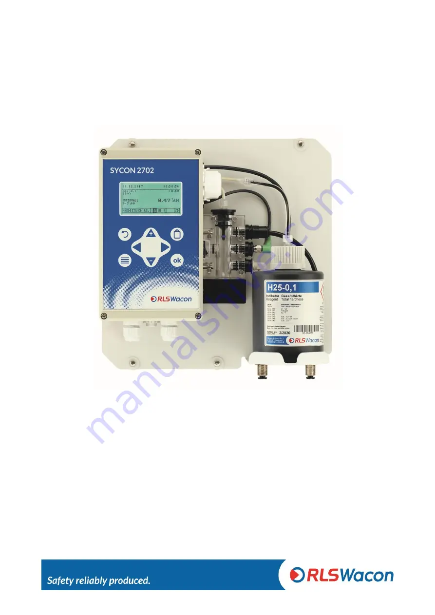
Страница 7: ...ng are ordered together the device is already mounted in the housing Article name Article no Analyzer SYCON 2702 with wall mounting 230 V version 30 010 162 Operating manual German 33 099 722 Housing for SYCON 2702 including wall mounting straps 33 099 005 The analyzer can be operated intuitively via menu using the graphic display and 8 keys on the controller housing Figure 1 Wall mounted SYCON 27...
Страница 8: ... actuator plugs inlet and outlet plugs are attached to the measuring chamber in the same way and can be quickly undone The measuring chamber which is always depressurised and always filled to prevent germs is in the middle The actuator plug with a white high power LED is in the middle of the measuring chamber The sensor system is located in the housing The agitator magnetic agitator which is firml...
Страница 9: ...tallation in the housing IP54 Storage temperature 0 C 45 C Ambient temperature 10 C 45 C Measuring water temperature 5 C 40 C Air humidity 20 90 RH without ice or condensate Pressure of inlet water min 0 5 bar max 5 bar recommendation 1 2 bar General inlet water clear colourless free of solids without gas bubbles Requirements for the water quality when measuring the water hardness pH 4 10 Iron 3 p...
Страница 10: ...CO3 mmol l e Ж these are shown in the display Accuracy Measuring accuracy 5 of the maximum reading of the respectively used reagent Repeat accuracy 2 5 of the maximum reading of the reagent used Please note Depending on the substances in the water there may be shifts in the reading that affect the measurement accuracy In such cases we recommend performing a hardness measurement by hand titration a...
Страница 11: ...tart analysis Flow switch Interval reset Analogue output 0 20 mA 4 20 mA Resolution 100 μA max load 750 Ω Maintenance interval Interval Maintenance works every 6 months Cleaning of measurement chamber At high ambient and water temperatures or water with high organic load the cleaning intervals may need to be shortened every 30 000 analyses or after 2 years of operation Cleaning of measurement cham...
Страница 12: ... 53 6 535 7 5 4 53 6 32 084 215 32 484 215 The following units are available for the analysis value dH f ppm CaCO3 mmol l e Ж these are shown in the display Reagents for monitoring carbonate hardness Name Reagent Measurement range Art no 500 ml bottle Art no 4 x 500 ml bottles dH mmol l f C25 1 0 3 7 5 0 11 2 68 0 5 13 4 32 086 125 32 486 125 C25 1 5 0 5 11 5 0 16 4 11 0 8 20 5 32 086 135 32 486 1...
Страница 13: ...nd connect it to the dosing pump Make sure that the connecting hoses are not twisted Do not switch on the device until all preliminary works have been completed and the housing is closed Now set the device settings on the device The sample water must be clear and free of solids Otherwise a filter should be provided in front of the analyzer Solids in the water can damage the solenoid valve or preve...
Страница 14: ...nstalled upright The wall bracket has four 6 mm holes for attaching the analyzer Figure Drill guide for attaching the analyzer without housing Position Description A Cable glands for electrical connection B Water inlet connection for hose with 6 mm outer diameter C Water outlet connection for hose with 6 mm outer diameter ...
Страница 15: ... which are attached to the rear side of the housing To open the device the available free space should be at least 450 x 350 mm W x H Figure Drill guide for attaching the analyzer in the housing Position Description A Cable glands for electrical connection B Water inlet connection for hose with 6 mm outer diameter C Water outlet connection for hose with 6 mm outer diameter D Door stop E Door locks...
Страница 16: ...ons and gaskets must be regularly checked and if necessary preventively replaced even if they show no visible damage Maintenance intervals must be complied with Before commissioning after maintenance make sure all connections threaded fittings and gaskets are properly installed Check that all housing parts are closed and filters or other parts connected to the device are installed correctly Remove...
Страница 17: ... be between 1 and 2 bar The hose length of the water outlet must not be longer than 2 m and must lead away vertically downwards The system must be able to relax freely against the atmospheric pressure There must be no back pressure greater than the inlet pressure The water is drained without pressure in an open funnel or drain Operation with unpressurised sample water If the sample water is depres...
Страница 18: ...ssible supply voltage is 85 305 VAC 47 440 Hz Open the lid of the controller by loosening the four screws in the corners of the lid Figure Back cover of the lid left side circuit board right side Position Description A Wi Fi optional B Battery holder C Solenoid valve port D Reagent pump port E Display port F Actuator plug LED port G Main switch port H 2 x relay I RGB sensor K Agitator port L Fuse ...
Страница 19: ...1 PE Earthing 2 PE Earthing 3 L power in Supply voltage between L and N 85 305 VAC 47 440 Hz 4 N power in Output terminals which are connected via the device switch Terminal designation Description 5 L power out Switched supply voltage between L and N 85 305 VAC 47 440 Hz 6 L power out 7 N power out 8 N power out Voltage The maximum connected capacity of all loads must not exceed 250 VAC 1 A Elect...
Страница 20: ... the symbol R1 is not marked in the display If the measured value of the sample exceeds the limit set in the SYCON relay 1 is energised and a connection from COM to NO is established In addition the symbol R1 is highlighted in black on the display Output 2 alarm relay 2 Device error notification Terminal designation Description Connection 12 COM Relay 2 COM common connection see page 9 Load capaci...
Страница 21: ... mA or 4 20 mA 16 Output 0 20 mA or 4 20 mA Current interface function The current interface is used to provide the present water hardness or device status as current output The current range can be selected between the settings 0 20 mA or 4 20 mA The maximum load is 750 Ω Selection options for current interface type From 0 20 mA value 4 20 mA value 0 20 mA status 4 20 mA status For more informati...
Страница 22: ...Interval reset Terminal designation Description 17 V 24 V auxiliary voltage to connect potential free outputs 18 Signal Signal input 19 GND Ground connection for the 24 V connection Input contact function A flow switch or other potential free switches can be connected to the input contact If the input contact is closed the symbol IN is highlighted in black on the display For more information see p...
Страница 23: ...nnections of the relays are all brought out potential free For switching external devices the internal network voltage or alternatively an external supply voltage can be used The connection to external controllers is usually established via the potential free contacts of the relays Figure Schematic plan view of connection terminals Voltage The supply voltage connected through the device switch is ...
Страница 24: ... an addition to the normal time interval The analyzer operates at a set time interval A signal can be delivered to the input via the switch and thus an additional analysis can be started When using this function the Sycon must be in automatic mode An additional analysis can also be triggered by pressing down the OK key for 3 seconds With a permanently connected input contact in the analysis start ...
Страница 25: ...can reduce reagent and power consumption As a flow switch a paddle can be used Potential free contact of a timer is also possible The examples below show various connection options at the input contact When using a flow switch the analyses are only carried out if a defined signal is present at the input input flow switch reports flowing water Depending on the installed contact the input can be con...
Страница 26: ...neration or after switching to the second water softening system the input contact is opened again The first analysis starts after one minute The following analyses are performed again in the programmed analysis interval Input contact is closed Analyses are stopped immediately and paused as long as the input contact remains closed As soon as the input contact is opened the analysis interval begins...
Страница 27: ... 1 Relay 1 output 1 remains switched in the position connection from COM to NO only for a programmed pulse duration when the limit value is exceeded Once the programmed pulse duration expires relay 1 output 1 switches back connection from COM to NC The next time the limit is exceeded relay 1 output 1 is switched again as a pulse This function is often used in combination with pilot distributors Pr...
Страница 28: ...s or external devices can be connected to process the measured value You can choose between a current output 0 20 mA value or 4 20 mA value In addition you must specify which current value of 20 mA corresponds to which total hardness carbonate hardness Programming Menu Settings Outputs Current loop type Programming Menu Settings Outputs Current loop calibration Enter the total hardness carbonate h...
Страница 29: ...face The operating status of the device can be transmitted via the current interface terminals 15 and 16 Programming Menu Parameters Outputs Current interface type Selection options 0 20 mA status 4 20 mA status Operating status Current interface 0 20 mA status 4 20 mA status Standby until first analysis is complete 3 5 mA 6 8 mA Fallen short of limit 7 5 mA 10 0 mA Limit exceeded 12 5 mA 13 6 mA ...
Страница 30: ...reagent plugs H Optical measurement path I Measurement chamber The locking pins can only be pulled up and cannot be pulled out K Agitator magnetic agitator L Drain plug M Actuator plug LED N Inlet plug O Solenoid valve concealed behind the reagent bottle P Wall bracket Q Reagent bottle 500 ml R Water inlet sample water Plug connection for plastic hoses with 6 mm outer diameter S Water outlet plug ...
Страница 31: ... of the display changes Background colour State White Device operates correctly Red Limit value exceedance or device error Figure Structure of the front cover of the controller Settings can be set via 8 keys Position Description A Display B Back discard input aborting a running analysis C Inserting a new reagent bottle D Main menu switching between main menu and analysis display E Arrow keys for n...
Страница 32: ...d and bad measurements Service Start analysis manual Pump reagent new bottle inserted Manual flushing Confirm maintenance Reset good and bad counter Diagnostic program testing of the actuators and sensors installed in the SYCON including the hardware Assistant The wizard guides you through all settings in the device and facilitates the commissioning History Displays the history of the last 100 mea...
Страница 33: ...ty F Set limit for relay 1 G Analysis result H Analysis step T 5 00 remaining time in minutes until next analysis I Status bar K Manual mode or automatic mode L Relay 1 de energised M Relay 2 energised fields highlighted in black are active N Digital input IN inactive O SD card present Simple starting of analysis press down the OK key for 3 seconds to start an analysis The analysis can be started ...
Страница 34: ...n with the and keys The setting is confirmed with the OK key If you do not want to change the setting you can leave the selection with the Back key In the picture below the active selection is the Yes key highlighted in black Display of selection list You can change the selection in a selection list using the and keys The setting is confirmed with the OK key If you do not want to change the settin...
Страница 35: ... is in the frame Now move the cursor to the OK field in the keyboard and press the OK key You will see the following information Current currently set value Minimum smallest settable value Maximum largest settable value Should the value at Current corresponds to your request then you do not need to re enter the number and you can immediately move the cursor to the OK field in the keyboard and conf...
Страница 36: ...gs Menu items Factory settings General Language German Analysis Unit dH Reagent H25 0 3 Limit value 0 5 dH Flushing time 120 seconds Auto Time interval 5 minutes Stop analysis No Control measurement No repetition Calibration factor 100 Input Input Start analysis Flow switch From Outputs Current interface type 4 20 mA values Calibrate current interface 0 9 dH Relay 1 Limit as permanent contact Rela...
Страница 37: ... can be changed separately in Menu Parameters again To start the wizard select Programming Menu Wizard The following steps are executed Automatic mode If the automatic mode is still active it must now be quit Select Yes or No with the arrow keys and and confirm with OK key Yes Terminate the automatic mode No Return to measured value view Language selection Please choose your language Press OK key ...
Страница 38: ...ith OK key Yes Reset the device to the recommended factory settings No The device retains the settings programmed by the user The factory settings can be found on page 36 Date Today is XX XX XX XX XX Do you want to set date and time Select Yes or No with and and confirm with OK key Yes Set date and time No The device keeps the date and time unchanged Adjust date Use the arrow keys and to move the ...
Страница 39: ...alyses and the maintenance date is set to 24 months Can be read in the Menu Info No The device retains the previous data Parameter Would you like to measure the total hardness or carbonate hardness alkalinity Select Total or Carbonate with and and confirm with OK key Total The total or residual hardness will be measured Carbonate The carbonate hardness will be measured When selecting total hardnes...
Страница 40: ...ng press the OK key Reagent Insert a new reagent bottle and press OK Insert new reagent bottle and press the OK key Reagent Reagent is pumped into the measuring chamber The pumping process can be stopped by pressing the OK key before the time has elapsed Make sure that the reagent has been pumped bubble free into the measuring chamber Reagent Has a full reagent bottle been used Select Yes or No wi...
Страница 41: ...ion of the sample cooler before the next step in order to rule out any danger from hot steam or hot water Flushing Press OK to flush the supply line and the measuring chamber Press OK key Flushing The solenoid valve opens and flushes the measuring chamber Here the previous flushing time is shown in the display This can be used as reference time to set the flushing time before analysis The flushing...
Страница 42: ... entry until the desired flushing time is within the range Now move the cursor to the OK field in the keyboard and press the OK key You will see the following information on the left Current currently programmed value Minimum smallest settable value Maximum largest settable value Should the value at Current corresponds to your request then you do not need to re enter the digits and you can immedia...
Страница 43: ... the OK key You will see the following information on the left Current currently programmed value Minimum smallest settable value Maximum largest settable value Should the value at Current corresponds to your request then you do not need to re enter the number and you can immediately move the cursor to the OK field in the keyboard and confirm with the OK key Auto Time interval Do you want the anal...
Страница 44: ...urrently programmed value Minimum smallest settable value Maximum largest settable value Should the value at Current corresponds to your request then you do not need to re enter the number and you can immediately move the cursor to the OK field in the keyboard and confirm with the OK key Control measurement How often should a limit exceedance be verified before notification Press OK key Control me...
Страница 45: ... on the device No Further analyses are also carried out after a limit has been exceeded Input Select the function of the input Press OK key Input You have the following options at the input Deactivated Start analysis Flow switch Interval reset Make a selection and confirm with the OK key If Start analysis is selected An analysis is started as soon as the Start Stop Input Inlet Contact terminal 17 ...
Страница 46: ...he analyses are stopped Immediately and paused as long as the input contact remains closed As soon as the input contact is opened the analysis interval begins However as the display does not yet show a value the first analysis is carried out after 1 min before the set analysis interval e g 5 min begins When using this function the Sycon must be in automatic mode Relay 1 Do you need a permanent or ...
Страница 47: ...l see the following information on the left Current currently programmed value Minimum smallest settable value Maximum largest settable value Should the value at Current corresponds to your request then you do not need to re enter the number and you can immediately move the cursor to the OK field in the keyboard and confirm with the OK key Relay 2 Relay 2 is used to indicate a device error Press O...
Страница 48: ...e type Use and to select the setting of the current interface type from the following options From 0 bis 20 mA value 4 bis 20 mA value 0 to 20 mA status 4 to 20 mA status When selecting status see further information on page 29 Make a selection and confirm with the OK key When selecting value Enter the value corresponding to 20 mA Press OK key Configuration ...
Страница 49: ...on the left side in a frame Repeat the entry until the desired number is in the frame Now move the cursor to the OK field in the keyboard and press the OK key You will see the following information on the left Current currently programmed value Minimum smallest settable value Maximum largest settable value Should the value at Current corresponds to your request then you do not need to re enter the...
Страница 50: ... RLS Wacon GmbH 49 0 5121 28126 0 info rls wacon de 50 Configuration Menu structure The following is an overview of the menu structure to give you an overview of all the functions of the analyzer ...
Страница 51: ...ing After switching on the automatic mode is active The first analysis is started after switching on at the programmed internal interval after 3 minutes All subsequent analyses are performed in the programmed interval Main menu The main menu can be opened by pressing the Menu key from the measured value view Menu item Description Automatic Changing between automatic and manual mode Parameter Setti...
Страница 52: ...an be reset in the service menu under the item good bad counters Behaviour in the event of power failure All settings of the device are stored on the SD card or in the internal memory In the event of a power failure all settings are available again after switching on the device If the device has been in automatic mode the analyzer automatically restarts after a short dwell time with an analysis ac...
Страница 53: ...cessed further Furthermore system files are present on the SD card bin The analyzer is fully functional even without an SD card but only the last 100 readings are saved internally The bottle level is stored on the SD card If the device is switched off and on again without an SD card the device cannot read in a bottle level from the SD card and therefore issues a BOB message bottle level below 10 I...
Страница 54: ...ice setting of the analyzer optional file Before replacing the analyzer you can transfer the saved device configuration directly to the new device The export is located in the menu under Parameters General Export settings The device configuration can be imported in the menu under Parameters General Import settings logfile dat System Date time stamp and device start This file is needed for internal...
Страница 55: ...ule wear protective goggles and gloves during maintenance to avoid contact with reagent cleaning fluid or other liquids The following maintenance intervals must be complied with Interval Maintenance and service every 6 months Cleaning of measurement chamber At high ambient and water temperatures or water with high organic load the cleaning intervals may need to be shortened every 30 000 analyses o...
Страница 56: ...ribed on the package insert For a trouble free operation it is important that not only the measuring chamber but also the actuator plug is cleaned with the white LED Take a cloth and moisten it with the FIT3000 included in the SYCON Clean Set and wipe the actuator plug thoroughly Please observe the following sequence when assembling Lubricate O rings 3 x J and 1 x C with technical Vaseline See pic...
Страница 57: ... unit on again Flush the measuring chamber Programming Menu Service Manual flush Feed the reagent into the measuring chamber Programming Menu Service Pump reagent Was a full reagent bottle used Select Yes or No and press the OK key Yes The cylinder filling level is set to 100 No The previous cylinder filling level in is retained Flush the measuring chamber again Programming Menu Service Manual flu...
Страница 58: ...control housing Remove the stirring blade Use a flat tip screwdriver to lever the reagent plug upwards When levering it out make sure that the locking pins are raised Pull up the locking pin for light rod plugs Take a non metallic object such as a plastic or wooden rod insert it into the actuator plug hole and push out the light rod plug The light rod stopper belongs to the optical measuring secti...
Страница 59: ...ake sure that all plugs are inserted into the measuring chamber up to the stop and only then locked otherwise the plugs can be damaged Connect the hose pump cassette to the reagent plug and to the reagent bottle Place the peristaltic pump cassette on the bracket so that it snaps into place Switch the unit on again Flush the measuring chamber Programming Menu Service Manual flush Feed the reagent i...
Страница 60: ...be reset The message Maintenance disappears from the display and only appears after the 24 months have elapsed or after 30 000 analyses then maintenance must be carried out again Programming Menu Service Confirm maintenance Select Yes or No with and and confirm with OK key Yes Maintenance counter is set to 30 000 analyses and the maintenance date is set to 24 months Can be read in the Menu Info No...
Страница 61: ...suring chamber Programming Menu Service Manual flush Feed the reagent into the measuring chamber Programming Menu Service Pump reagent until the reagent reaches the measuring chamber free of bubbles Then press the OK key to stop purging the reagent line Has a full reagent bottle been used Select Yes or No and press the OK key Yes The bottle fill level is set to 100 No The previous bottle fill leve...
Страница 62: ...fo screen Programming Menu Info If the limit is exceeded the bad counter is increased and if the limit is undershot the good counter is increased This counter can be used to assess the function of a water softening system Here the number of bad measurements should be much smaller than that of the good measurements The counters can be reset in the menu Programming Menu Service Good bad counter ...
Страница 63: ...uch as 0 012 dH cannot be used Analyse the water in the laboratory in parallel Calculate the correction factor for the analyzer using the following formula 𝐶𝑜𝑟𝑟𝑒𝑐𝑡𝑖𝑜𝑛𝑓𝑎𝑐𝑡𝑜𝑟 𝑀𝑒𝑎𝑠𝑢𝑟𝑒𝑑𝐿𝑎𝑏𝑜𝑟𝑎𝑡𝑜𝑟𝑦 𝑀𝑒𝑎𝑠𝑢𝑟𝑒𝑑𝐴𝑛𝑎𝑙𝑦𝑠𝑒𝑟 100 Set the correction factor in the device under the specified path Programming Menu Parameters Analysis Calibration factor Example of calculation MeasuredLaboratory 0 55 dH Display value fr...
Страница 64: ...As part of the product improvement you will receive software updates via your dealer or our website Should this be required your dealer will send you a file called TA27xxx bin To perform a software update proceed as follows Switch off the device and disconnect the power supply Open the controller housing with 4 screws and remove the SD card Copy the TA27xxx bin file to the SD card using a computer...
Страница 65: ...case check the electrical connection of the solenoid valve in the device If the connectors are properly seated measure the voltage with valve open between the connections on the valve This should be at 24 VDC If this is the case a fault in the electronics is to be excluded and the solenoid valve is defective To exit move the cursor to Exit and press the OK key The positioning of the connectors can...
Страница 66: ... exit move the cursor to Exit and press the OK key The positioning of the connectors can be found on page 20 Current interface An ammeter is required to test the current interface Measurements are made between terminals 15 and terminal 16 The output current is shown in the display as I xx mA The same value should also be measured at the two terminals Tolerance 0 3 mA Please note the accuracy of yo...
Страница 67: ...ried out correctly Check whether there is sufficient reagent in the reagent bottle Check the connection hose between the reagent bottle and the hose pump for air bubbles If necessary convey the reagent until the hose is completely filled with the reagent Check that the blue O ring is on the reagent plug Check if there is water in the measuring chamber Check if the agitator blade is in the measurin...
Страница 68: ... RLS Wacon GmbH 49 0 5121 28126 0 info rls wacon de 68 Annex Spare parts ...
Страница 69: ... ø 6 x 4 mm 33 090 124 Q Inlet hose 50 mm long ø 6 x 4 mm 33 090 112 R Solenoid valve SYCON 24 V 33 090 157 S Suction lance 33 090 011 T Bulkhead plug connector straight 33 090 116 V O ring 5 28 x 1 78 33 090 215 U Luer lock connection 33 090 414 Spare parts without illustration Article name Article no Measuring chamber including position E M N O L 33 190 700 Display circuit board 33 033 607 Main ...
Страница 70: ...purpose It contains all the aids required for cleaning as well as the cleaning fluid FIT 3000 Information on performing maintenance can be found in the chapter Maintenance and Service starting on page 55 Article name Article no Maintenance set for SYCON 2702 Includes the following articles 1 x 33 090 008 bottle connector 1 x 33 090 011 suction lance 1 x 33 090 217 O ring 16x2 4 x 33 090 210 O ring...
Страница 71: ...l male thread Ball valve with socket ends made of 1 4408 V4A stainless steel with 1 4 inch cylindrical internal thread Straight screwed connection nickel plated brass 1 4 inch cylindrical external thread with sealing ring hose connection with outer diameter of 6 mm 5 meters of plastic hose with outer diameter of 6 mm 5 meters of plastic hose with outer diameter of 6 mm 33 000 701 Sample cooler The...
Страница 72: ... RLS Wacon GmbH 49 0 5121 28126 0 info rls wacon de 72 Annex Declaration of conformity ...
Страница 73: ...49 0 5121 28126 0 Fax 49 0 5121 28126 20 info rls wacon de www rls wacon de Managing Directors Dr Claudia Rudolph Dr Sascha Matern Register court District Court of Hildesheim Register number HRB 200 889 VAT Id DE259530002 Photo back Vitali Vidnevski employee RLS Wacon GmbH 2015 Subject to modifications and errors 12 03 2020 ...
Страница 74: ... RLS Wacon GmbH 49 0 5121 28126 0 info rls wacon de 74 ...