24
•
Installation
AirLink T3A Operator’s Manual
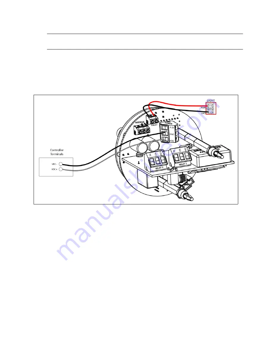
2. Locate the power (RED) and ground (BLACK) wires on the alarming device.
WARNING: Use appropriate construction technique to maintain the explosion-proof
classification of the assembly.
3. Feed the alarming device’s wires through the 3/4 NPT power hub and into the enclosure.
4. Locate the fault terminal block on the control board.
5. Connect the external fault device power (RED) wire to the
+
terminal.
6. Connect the external fault device ground (BLACK) wire to the
-
terminal.
Figure 9: Fault Terminal Wiring


