


72-2102-07 Beacon 200 Operator’s Manual • 12
•
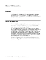
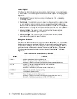
Channel relays.
The four channel relays are above the alarm terminal
strip (see Figure 1). These relays are dedicated to specific channels
and alarm levels.
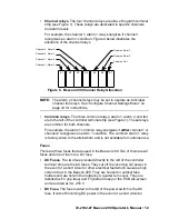
For example, the channel 1, alarm 1 relay energizes if channel 1
recognizes an alarm 1 condition. Figure 4 below illustrates the
allocation of the channel relays.
NOTE:
The alarm 2 channel relays may be set to operate as individual
channel fail relays. See “Configure Channel Settings Menu” on
page 34 for instructions.
•
Common relays.
The three common relays, alarm 1, alarm 2, and fail,
are to the left of the controller terminal strip (see Figure 1). These relays
are common for both channels.
For example, the alarm 1 common relay energizes if
either
channel 1 or
channel 2 recognizes an alarm 1 condition. The common alarm 1 relay
is factory wired to the strobe/horn and is not available for customer use.
Fuses
There are three fuses that are used in the Beacon 200. Two of them are AC
fuses and one of them is a DC fuse.
•
AC Fuses.
The two fuses located directly to the left of the controller
terminal strip are the AC fuses. They cut off the incoming AC power in
the event of a short circuit or other electrical fault which causes a high
current draw in the Beacon 200. They are housed in vertical fuse
holders and are held in the holder by a quarter turn cover. They are
labelled as F2 (top fuse) and F3 (bottom fuse) on the PCB silk-screen
and are rated at 3 A, 250 V.
•
DC Fuse.
The fuse located to the left of the power switch is the DC
fuse. It cuts off incoming DC power in the event of a short circuit or
K1
K2
K3
Common Al arm 1
Common Al arm 2
Common Fail
K5
K6
K7
K4
Channel 2, Alarm 2
Channel 2, Alarm 1
Channel 1, Alarm 2
Channel 1, Alarm 1
Figure 5. Beacon 200 Channel Relay Allocation


