


RIX Industries
040910-01
Page 10
5.4
Gas Filter Service
Every 2000 hours of running time, the interstage and discharge filters should be inspected and
cleaned or replaced. Failure to do so at the specified interval may result in poor valve performance
or process plumbing constriction in extreme cases of filter element contamination.
5.5
Compressor Valve Service
The valves should be inspected, cleaned, and, if necessary, replaced every 4000 hours or if
pressures vary from normal, noise is detected, or abnormally high temperatures are observed.
Severe leakage will cause overheating of the suction plumbing just prior to the cylinder head.
5.6
Running Gear Inspection
All compressor running gear should be inspected every 2000 hours. Belt alignment and tension as
well as all bearings should be inspected at this time. Belt should deflect ½-¾” at the mid span with
approximately 10 lbs.
of
force applied. Bearings should be inspected to verify smooth rotation and
adequate lubrication. At a minimum relubricate the connecting rod needle bearing after 4000 hours
of operation and replace after 8000 hours operation.
5.7
Piston Ring Replacement
Every 2000 hours the 2
nd
stage piston rings, expanders, and riders should be replaced and every
3000 hours the 1
st
stage piston rings, expanders, and riders should be replaced. As the compression
rings wear their ability to seal is diminished. Excessive wear will result in lower compressor
capacity, more frequent compressor operation, and unnecessary wear on other components. With
extreme wear the compressor will not be able to compress to the design pressure. If the
compressor starts and stops more frequently, fails to make pressure, or has degraded flow capacity,
the rings should be replaced. There is risk of damaging the cylinder liners if the rings wear out
completely.
Note:
piston rings are design to seal dynamically only. Leakage in standby is normal.
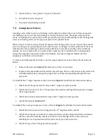
5.8
Compression Cylinder Inspection
Excess piston to cylinder clearance, caused by wear to cylinder bores, will significantly decrease
ring life. Cylinder bores should be observed for wear at ring change-outs or if ring life has
significantly decreased. It is good practice to measure the diameter and surface finish of the
cylinder bores whenever the cylinders are removed or when ring life drops from normal. Maximum
wear will normally occur 1/3 to 1/2 way down the bore. A bore gauge is the best way to measure
wear. Check diameter at several depths for wash-boarding – see
Section 7.10
for wear limits. Some
surface roughness is needed to allow engraining of seal material in the bore. Both cylinders should
have a surface finish of 12-16 µin Ra crosshatch. If the cylinder bore surface finish is out of
tolerance it will reduce ring life.
Содержание 2PS-15-115
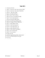
Страница 37: ...RIX Industries 040910 01 Page 28 FIGURE 1 COMPRESSOR CROSS SECTION FASTENER DETAIL ...
Страница 38: ...RIX Industries 040910 01 Page 29 FIGURE 2 COMPRESSOR CROSS SECTION PUMP DETAIL ...
Страница 39: ...RIX Industries 040910 01 Page 30 FIGURE 3 1ST STAGE VALVE DETAIL ...
Страница 40: ...RIX Industries 040910 01 Page 31 FIGURE 4 2ND STAGE VALVE DETAIL ...
Страница 41: ...RIX Industries 040910 01 Page 32 FIGURE 5 EXTERIOR FASTENER DETAIL ...
Страница 42: ...RIX Industries 040910 01 Page 33 FIGURE 6 MOTOR AND CONTROL BOX MOUNTING ...
Страница 43: ...RIX Industries 040910 01 Page 34 FIGURE 7 SUCTION PLUMBING DETAIL ...
Страница 44: ...RIX Industries 040910 01 Page 35 FIGURE 8 INTERSTAGE PLUMBING DETAIL ...
Страница 45: ...RIX Industries 040910 01 Page 36 FIGURE 9 FINAL DISCHARGE PLUMBING DETAIL ...
Страница 46: ...RIX Industries 040910 01 Page 37 FIGURE 10 COOLING FAN SUB ASSEMBLY DETAIL ...
Страница 47: ...RIX Industries 040910 01 Page 38 FIGURE 11 BELT INSTALLATION DETAIL ...
Страница 48: ...RIX Industries 040910 01 Page 39 FIGURE 12 GUARD MOUNTING DETAIL ...
Страница 49: ...RIX Industries 040910 01 Page 40 FIGURE 13 CONTROL BOX DETAIL 1 OF 2 ...
Страница 50: ...RIX Industries 040910 01 Page 41 FIGURE 14 CONTROL BOX DETAIL 2 OF 2 ...
Страница 51: ...RIX Industries 040910 01 Page 42 FIGURE 15 CONTROL BOX WIRING DIAGRAM ...
Страница 52: ...RIX Industries 040910 01 Page 43 FIGURE 16 ELECTRICAL SCHEMATIC ...
Страница 53: ...RIX Industries 040910 01 Page 44 FIGURE 17 FLOW SCHEMATIC ...
Страница 57: ......
Страница 58: ......


