Instruction Manual IM‐116
CUSTOMER'S INFORMATION BOX
CONTENTS ARE INDEPENDENT OF RIVERHAWK DOCUMENT CONTROL
215 Clinton Road
New Hartford, NY 13413
Tel: +1 315 768 4855
Fax: +1 315 768 4941
Email: [email protected]
REV
373A4028
GE DRAWING NUMBER
Revision H
Page 15 of 29
CAUTION
DO NOT EXCEED THE MAXIMUM PRESSURE VIBROSCRIBED ON THE PULLER BODY. Excessive
pressure can damage the stud and the puller screw
For the procedures of Section 9.3 excessive stretch variation or low stretch values can be
corrected by retensioning all or selected studs to the pressure values stated in the above table.
Have final stretch values approved by the supervisor responsible for the installation.
10.0 Thread Locking
Once pulling and tensioning is complete all studs and nuts must be locked in position. The lock
nuts used in the turbine/coupling and coupling/generator connections employ a mechanical
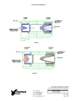
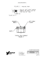
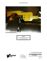
locking feature. These mechanical lock nuts have two set screws located on the top face, see
Figure 4.
Before threading the nut onto the stud check to be certain that the set screws are free to turn.
Once the nut is seated torque the set screws to the values specified in the following table.
When seated and torqued to the values specified the load created by the set screw displaces
the thread of the nut in the area of the web creating the desired locking action.
Stud Size
Set Screw Size
Torque
2.784"
[71 mm]
3/8"‐24 UN
200 in∙lbs ‐ 250 in∙lbs
[22.6N∙m – 28.2 N∙m]
2.283"
[58 mm]
1/4"‐28 UN
80 in∙lbs ‐ 90 in∙lbs
[9.0 N∙m – 10.2 N∙m]
11.0 Stud/Nut removal
Removal is accomplished as follows:
1.
Using a wire brush and shop air clean the internal tapered thread of the stud to remove
any debris/deposits which may have accumulated during service. (see section 5.2.1)
2.
With an Allen‐wrench loosen the two locking set screws but do not remove from the nut
see Figure 4.
3.
Install the appropriate puller tool to the stud as described in Section 8.0.


