4 Assembly and connection
Rittal cooling unit assembly and operating instructions
11
EN
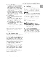
4.5.3 Three-phase devices
– The three-phase version must be connected to a
TN network with star earthing via a motor circuit-
breaker for plant protection (current setting as per
the rating plate). Three-phase units with special
voltages must be protected with a motor circuit-
breaker for transformer protection (category AC-3)
as per the rating plate.
– Units designed for three phase 400/460 V feature
additional monitoring of the rotary field or the ab-
sence of a phase. If the rotary field is incorrect or a
phase is absent, the unit will not run.
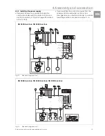
4.5.4 Door limit switch
– Each door limit switch must only be assigned to
one cooling unit.
– Several door limit switches may be connected in
parallel and operated on one cooling unit.
– The minimum cross-section of the connection
cable is 0.3 mm
2
for a cable length of 2 m.
We recommend the use of a shielded cable.
– The line resistance to the door limit switch must not
exceed a maximum of 50
Ω
.
– The door limit switch only supports a floating con-
nection; no external voltages.
– The contact of the door limit switch must be closed
when the door is open.
The safety extra-low voltage for the door limit switch
is provided by the internal power pack: Current
approx. 30 mA DC.
• Connect the door limit switch to terminals 1 and 2
of the connector.
4.5.5 Notes on the flicker standard
The flicker limits specified in standard EN 61 000-3-3
or -3-11 are adhered to, provided the supply im-
pedance is less than approx. 1.5
Ω
.
Where necessary, the unit operator should measure
the connected impedance or consult the responsible
power supply company. If there is no way of influ-
encing the supply impedance and sensitive installed
components (e.g. BUS) are subjected to interfer-
ence, a line reactor or starting-current limiting device
should be connected upstream of the cooling unit to
restrict the startup current of the cooling unit.
4.5.6 Potential equalisation
If, for EMC reasons, the unit is to be integrated into
the existing potential equalisation system at the
customer, a conductor with a larger nominal cross-
section can be connected to the potential equali-
sation connection point (attachment points) on roof-
mounted cooling units.
According to the standard, the PE conductor in
the mains connection cable is not classified as an
equipotential bonding conductor.
4.6 Carrying out the electrical installation
4.6.1 Bus connection
(only in conjunction with several units
with an e-Comfort controller)
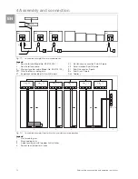
When using several cooling units, the serial device
interface X2 can be used to connect up to ten cooling
units with the bus cable (Model No. SK 3124.100).
When interconnecting, please note the following:
– De-energise the cooling units to be connected.
– Ensure proper electrical insulation.
– Make sure the cables are not laid in parallel to
power lines.
– Make sure that the lines are short.
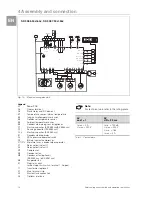
4.6.2 Connection X3 for serial interface
The interface card (Model No. SK 3124.200) may be
connected to X3. This is used to evaluate system
messages in a PLC, for remotely setting parameters
and monitoring, or for integration into the facility
management system.
Note:
The electrical signals at the X2 interface are
of an extra-low voltage (not extra-low safety
voltages to EN 60 335-1).
Caution!
Regarding the last slave unit in the
group, do not, under any circumstances,
connect the remaining socket of the
Y cable SK 3124.100 into interface X3
of the cooling unit!
Содержание SK 3273.xxx
Страница 2: ......


