background image

CZ

38

Rittal PDU metered/metered plus/switched/managed

V závislosti na verzi PDU mohou být volné zásuvky zabezpečeny kryty pro zásuvky C13/C19,
které jsou dostupné jako příslušenství.

Pokud se instalace nezdařila: viz bod 1. 1

6

Nastavení PDU

Pokud jednotka PDU nemůže být zařazena do sítě s tímto nastavením, nastavení můžete změnit 
pomocí displeje nebo webového rozhraní PDU.

6.1


Nastavení pomocí displeje

Poznámka:
Při připojení zařízení k PDU dbejte na maximální zatížení jednotlivých zásuvek (C13:
10 A; C19: 16 A; Schuko (CEE 7/3): 16 A; BS 1363 (UK): 13 A).

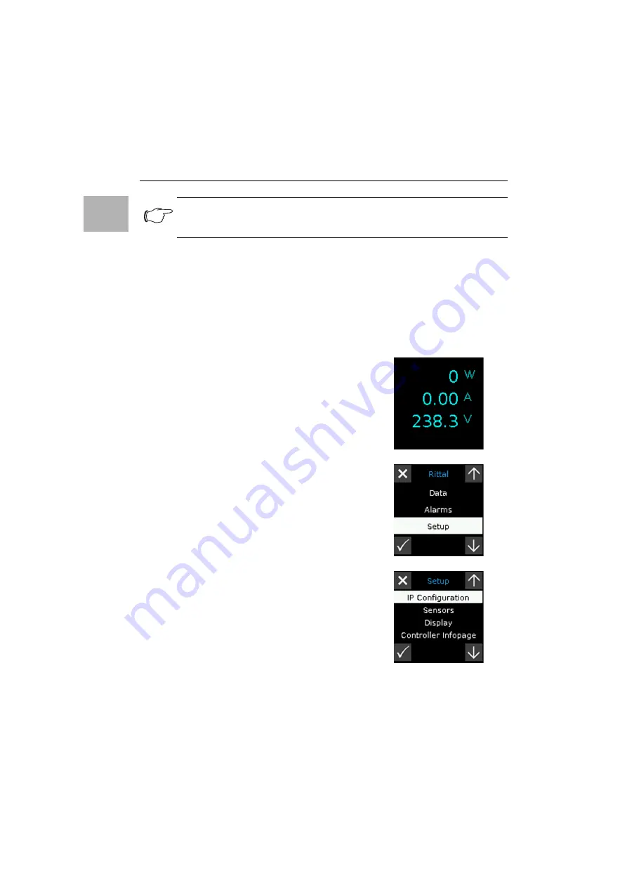
Pokud  je  displej  vypnutý:  Stiskněte  jakoukoliv  klávesu. 
Zobrazí se menu s informace o výkonu na fázi.

Stiskněte klávesu "Esc" (obr. 12, pol. 1) pro zobrazení 
hlavní menu 

Rittal

.

Zvolte položku "Setup" a stiskněte klávesu "Zpět" pro 
potvrzení Vašeho výběru (obr. 12, pol. 4).

Instalace a provoz, nastavení PDU

Содержание 7979.202

Страница 1: ...233 7979 234 7979 235 7979 238 7979 239 7979 240 7979 242 7979 303 7979 304 7979 310 7979 311 7979 312 7979 313 7979 314 7979 330 7979 331 7979 332 7979 333 7979 334 7979 335 7979 338 7979 339 7979 340 7979 342 7979 402 7979 403 7979 404 7979 410 7979 411 7979 412 7979 413 7979 414 7979 430 7979 431 7979 432 7979 433 7979 434 7979 435 7979 438 7979 439 7979 440 7979 442 7979 502 7979 503 7979 504 ...

Страница 2: ...ch användas med de systemtillbe hör som föreskrivits av Rittal Säkerhetsinstruktioner Denna produkts hölje får inte öppnas Produkten får endast köras inom de angivna gränser som specificeras i avsnittet om tekniska data Pro dukten får inte komma i kontakt med vatten eller aggressiva eller bränn bara gaser och ångor Frånkoppling av en utgångskontakt innebär inte att lasten är säkert frånskild Questo...

Страница 3: ... при соблюдении граничных условий заданных в техни ческих характеристиках Не допускается контакт продукта с водой агрессивными или легковоспламеняющимися газами или парами Отключение розетки не является безопасным отключением на грузки Αυτό το προϊόν χρησιμεύει αποκλειστικά ως πρόσθετος εξοπλισμός για τη διάθεση και διανομή της τροφοδοσίας ηλεκτρικής ενέργειας σε εγκαταστάσεις πληροφοριακών συστημ...

Страница 4: ...tki Ohišja tega izdelka ni dovoljeno odpirati Izdelek lahko uporabljate samo v okviru omejitev ki so določene v tehničnih podatkih Izdelek ne sme priti v stik z vodo agresivnimi in vnetljivimi plini ter parami Izklop izhodne vtičnice ne zadostuje za varen odklop odjemalca Tento produkt slúži výlučne ako príslušenstvo na zabezpečenie dodávky a rozvodu elektrickej energie pre zariadenia informačných...

Страница 5: ...í PDU basic metered metered plus switched managed Abb Fig Obr 2 s Halter TS IT VX IT für Profilschiene standard d Halter VX IT für Profilschiene dynamic s TS IT VX IT bracket for standard mounting angles d VX IT bracket for dynamic mounting angles s Závěs pro profilové lišty TS IT a VX IT Standard d Závěs pro profilové lišty VX IT Dynamic Abbildungen Figures Figures Abbildungen Figures Obrázky ...

Страница 6: ... Assembling TS IT VX IT bracket Montáž závěsu na profilovou lištu TS IT VX IT Abb Fig Obr 4 Für den Transport wird eine Verschraubung der Halter empfohlen A screw connection of the holders is recommended for transport Pro přepravu se doporučuje závěsy přišroubovat Abbildungen Figures Obrázky ...

Страница 7: ... TS IT VX IT und PDU Assembling TS IT VX IT extension and PDU Support Instalace adaptéru pro TS IT VX IT a PDU Abb Fig Obr 6 Demontage Verlängerung und Halter TS IT VX IT Dismantling TS IT VX IT extension and bracket Demontáž adaptéru a závěsu pro TS IT VX IT Abbildungen Figures Obrázky ...

Страница 8: ... plus switched managed Abb Fig Obr 7 Montage Universalhalter Mounting universal bracket Montáž univerzálního závěsu Abb Fig Obr 8 Montage an Kabeltrasse Mounting to cable route Montáž na kabelovou trasu Abbildungen Figures Obrázky ...

Страница 9: ... Montage kompakte Horizontal PDU in 19 Ebene Installation of the compact horizontal PDU in the 19 level Montáž kompaktní 19 PDU jednotky do 19 roviny Abb Fig Obr 10 Montage Kabelbefestigung Mounting cable attachment Montáž aretace kabelu Abbildungen Figures Obrázky ...

Страница 10: ...ched managed Beschreibung Bedien und Anzeigeelemente siehe Abschnitt 5 1 Operating and display elements as well as connectors for PDU metered metered plus switched ma naged Operating and display elements description see section 5 1 Ovládací a zobrazovací prvky a konektory pro PDU metered metered plus switched managed více informací k ovládání a displeji naleznete v sekci 5 1 Abbildungen Figures Ob...

Страница 11: ...cription of the website see section 6 2 Webové rozhraní pro PDU metered metered plus switched managed více informací k webovému rozhraní naleznete v sekci 6 2 Abb Fig Obr 14 Farbkennung der einzelnen Phasen und Steckplätze Colour coding of individual phases and slots Barevné označení pro jednotlivé fáze a zásuvky Abb Fig Obr 15 Zuordnung der Steckplätze zur Sicherung Assignment of slots to the fus...

Страница 12: ...e auf dem Typenschild der PDU aufgedruckt sind Network Info enthält alle eingestellten Netzwerkinformationen System Info enthält alle Systeminformationen Phase 1 Info Phase 2 Info und Phase 3 Info enthalten die Messwerte der jeweiligen Phase Diese werden ca alle 3 s neu berechnet und aktualisiert Controller Info enthält Informationen die auf dem Typenschild des PDUi Controllers aufgedruckt sind Di...

Страница 13: ...heiden PDU metered Energiemessung an der Einspeisung je Phase d h Leistungsbedarf eines gesamten IT Racks ohne Schaltfunktion mit Display und Netzwerkschnittstelle PDU metered plus Energiemessung an jedem Ausgangssteckplatz ohne Schaltfunktion mit Display und Netzwerkschnittstelle PDU switched Energiemessung an der Einspeisung je Phase d h Leistungsbedarf eines gesamten IT Racks mit Schaltfunktion...

Страница 14: ...tallation und Bedienung PDU 5 1 Bedien und Anzeigeelemente Die Bedien und Anzeigeelemente sind in Abb 12 dargestellt Hierbei richtet sich die Anzeigerichtung des Displays sowie die Belegung der vier Tasten seitlich neben dem Display nach der Montagerichtung der PDU In der Legende zu Abb 12 ist die Tastenbelegung für den Montagefall dargestellt dass der elektrische Anschluss der PDU unten liegt Wir...

Страница 15: ...U an die Stromversorgung leuchtet die grüne Power LED Abb 12 Pos 7 und der Systemstart der PDU beginnt automatisch Bei angeschlossenem Netzwerk leuchten die Link und die Status LED an den RJ 45 Buchsen Abb 12 Pos 9 und 10 Nach wenigen Sekunden beginnt die Multi LED zur Statusanzeige blau zu blinken und zeigt an dass der Bootvorgang läuft Abb 12 Pos 8 Bei PDU switched und PDU managed Nach Abschluss...

Страница 16: ...e Einstellungen über das Display oder die Website der PDU geändert werden 6 1 Einstellung über das Display Hinweis Beachten Sie beim Anschluss der Verbraucher die maximale Belastung pro Steckplatz der PDU C13 10 A C19 16 A Schuko CEE 7 3 16 A BS 1363 UK 13 A Wenn das Display ausgeschaltet ist Drücken Sie eine beliebi ge Taste Es erscheint ein Menü mit der Anzeige der Leistun gen pro Phase Drücken ...

Страница 17: ...weiten Stelle der PIN zu wechseln Drücken Sie wiederum so oft die Aufwärts bzw die Ab wärts Taste bis die gewünschte Ziffer an der zweiten Stelle der PIN angezeigt wird Wechseln Sie zur dritten und vierten Stelle der PIN und stellen Sie diese analog ein Hinweis Um Zugriff auf das Konfigurationsmenü zu erhalten ist die PIN 1221 voreingestellt Die se PIN kann über die Website der PDU geändert werden...

Страница 18: ...mit Return Drücken Sie die Abwärts Taste um auf die 2 Seite des Me nüs IP v4 Setup zu wechseln Ändern Sie ggf die Subnetzmaske auf die gewünschte Einstel lung und bestätigen Sie sie mit Return Drücken Sie die Abwärts Taste um auf die 3 Seite des Me nüs IP v4 Setup zu wechseln Ändern Sie ggf das Gateway auf die gewünschte Einstellung und bestätigen Sie sie mit Return um die geänderten Netz werkeins...

Страница 19: ...way korrekt ein Wählen Sie alternativ die Einstellung DHCPv4 statt Manual für eine automatische IP Vergabe Klicken Sie auf die Schaltfläche Save um die Einstellungen zu speichern Ändern Sie die Netzwerkeinstellungen Ihres Computers auf die ursprünglichen Werte der IP Adresse sowie der Subnetzmaske ab Trennen Sie das Netzwerkkabel zu Ihrem Computer Verbinden Sie die PDU mit einem Netzwerkkabel mit ...

Страница 20: ...in am CAN Bus angeschlossenes Gerät hat den Status Warnung Rotes Dauerlicht Die PDU oder mindestens ein am CAN Bus angeschlossenes Gerät hat den Sta tus Alarm Anzeige der Statusänderung an der Multi LED des angeschlossenen Sensors Dauerhaft blaues Blinken Kommunikation über den CAN Bus Grünes Blinken bei Messwertänderung oder spätestens alle 5 Sekunden Der Anschluss weiterer Sensoren erfolgt als D...

Страница 21: ...gangsspannungsbereich L N 90 V 260 400 V AC 50 60 Hz Eingangsstrom 16 A 32 A je nach Variante Anzahl der Phasen 1 bzw 3 je nach PDU Variante Farbliche Gehäusemarkierungen der Phasen Sicherheits stromkreise nur 3 phasige Ausführungen L1 Pink L2 Schwarz L3 Weiß Anschlusskabel Typ H05 VV Aderanzahl 3 1 phasige PDU bzw 5 3 phasige PDU Type Electrical design Supply cord Add on supply Add on per phase A...

Страница 22: ...4 Pos 2 Phase 3 L3 Weiß Abb 14 Pos 3 Für die PDU Variante 32 A wird zusätzlich die Zuordnung der Sicherungen zu den einzelnen Steck plätzen durch farblich gleiche Dreiecke gekennzeichnet Hierbei gelten diejenigen Dreiecke als zusam mengehörig die sich auf der gleichen Seite der PDU befinden siehe Abb 15 Pos 1 und 2 9 Service Zu technischen Fragen wenden Sie sich bitte an Tel 49 0 2772 505 9052 E M...

Страница 23: ...all system information Phase 1 Info Phase 2 Info and Phase 3 Info contain the measured values of the associated phase These values are recalculated and refreshed every 3 seconds approx Controller Info contains the information printed on the PDUi controller rating plate The following operating instructions refer to the PDU standard range unless otherwise stated in the text Minor deviations may aris...

Страница 24: ...iants with the following distinguishing features PDU metered Energy measurement at the infeed per phase i e output requirement of an entire IT rack no switching function with display and network interface PDU metered plus energy measurement at each individual outlet socket no switching function with display and network interface PDU switched Energy measurement at the infeed per phase i e output re...

Страница 25: ...f the PDU 5 1 Operating and display elements The operating and display elements are shown in fig 12 The display direction and the assignment of the four keys at the side next to the display depends on the installation direction of the PDU The key to fig 12 shows the key assignment for the installation case with electrical connection of the PDU at the bottom If the PDU is installed with the electri...

Страница 26: ... If connected to a network the Link and Status LEDs on the RJ 45 jack will be illuminated fig 12 item 9 and 10 After a few seconds the multi LED for status display will start to flash blue indicating that booting is in progress fig 12 item 8 For PDU switched and PDU managed The Status LEDs on the slots will be activated simultaneously and then switched off again a few seconds later Once booting is...

Страница 27: ...f the PDU cannot be incorporated into the network with these settings the settings can be amended via the display or the PDU website 6 1 Settings via the display If the display is switched off Press any key A menu will appear showing the power per phase Press the Esc key fig 12 item 1 to display the Rittal main menu Select the Setup entry and press the Return key to confirm your selection fig 12 i...

Страница 28: ...key to move to the second position of the PIN Once again keep pressing the Up key or the Down key until the required digit is displayed in the second position of the PIN Move to the third and fourth positions of the PIN and set them in the same way Note 1221 is the preset PIN for accessing the configuration menu This PIN can be modified via the PDU website Make a note of the new PIN number and kee...

Страница 29: ...in the network and confirm with Return Press the Down key to move to the page 2 of the IP v4 Set up menu If necessary amend the subnet mask to the required setting and confirm with Return Press the Down key to move to the page 3 of the IP v4 Set up menu If necessary amend the gateway to the required setting and confirm with Return to save the altered network settings The new network settings will ...

Страница 30: ...nge your settings Change the network settings of your computer to its original values for the IP address and the subnet mask Disconnect the network cable from your computer Connect the PDU to your Ethernet LAN with a network cable For any required software updates please visit www rittal com or contact Rittal Service see section 9 6 3 Connection of sensors A maximum of eight sensors and handle sys...

Страница 31: ... to the CAN bus has the status Alarm Status change display on the multi LED of the connected sensor Continuous blue flashing Communication via the CAN bus Green flashing When the measured value changes or at the latest every 5 seconds Further sensors are connected as daisy chain If necessary connect another component e g another sensor type to the second free CAN bus interface of the first compone...

Страница 32: ...rective 2014 30 EU IEC EN 62368 Input voltage range L N 90 V 260 400 V AC 50 60 Hz Input current 16 A 32 A depending on variant No of phases 1 or 3 depending on PDU variant Colour coding of the phases fuse circuits 3 phase ver sions only L1 pink L2 black L3 white Connection cable type H05 VV No of wires 3 5 single phase 3 phase PDU Type Electrical design Supply cord Add on supply Add on per phase ...

Страница 33: ...hase 2 L2 black fig 14 item 2 Phase 3 L3 white fig 14 item 3 For the PDU variant 32 A the assignment of the fuses to the individual slots is also indicated with iden tically coloured triangles Whereby those triangles located on the same side of the PDU belong togeth er see fig 15 item 1 and 2 9 Service For technical questions please contact Tel 49 0 2772 505 9052 E mail info rittal de Homepage www...

Страница 34: ...informace System Info obsahuje všechny systémové informace Phase 1 Info Phase 2 Info a Phase 3 Info obsahuje měřené hodnoty jednotlivých fází Tyto hodnoty jsou obnovovány přibližně každé 3 sekundy Controller Info obsahuje měřené hodnoty jednotlivých fází Tyto hodnoty jsou obnovovány přibližně každé 3 sekundy Následující provozní pokyny se vztahují ke standardním jednotkám PDU pokud není v textu uv...

Страница 35: ...edujícími funkcemi PDU metered měřící funkce na napájení každou fázi tzn spotřeba celé IT skříně nemá funkci spínání vybavena displejem a síťovým rozhraním PDU metered plus měřící funkce na jednotlivé výstupní zásuvky nemá funkci spínání vybavena displejem a síťovým rozhraním PDU switched měřící funkce na napájení každou fázi funkce spínání jednotlivých výstupních zásuvek vybavena displejem a síťo...

Страница 36: ...sou součástí balení PDU 5 Instalace a provoz 5 1 Ovládací a zobrazovací prvky Ovládací a zobrazovací prvky jsou znázorněny na obr 12 Směr zobrazení a přiřazení čtyř kláves na straně vedle displeje závisí na směru instalace PDU Klíč na obr 12 zobrazuje polohu kláves pro instalační polohu s přívodem dole Pokud je PDU instalováno s přívodem nahoře přiřazení kláves 1 a 5 stejně jako 2 a 4 je obráceno ...

Страница 37: ...ní Po připojení PDU k napájení se rozsvítí zelená LED indikující napájení obr 12 položka 7 a PDU se automaticky spustí Pokud jste PDU připojili k síti LED Indikace přenosu a Stav na portu RJ 45 budou svítit obr 12 položky 9 a 10 Po několika sekundách začne stavová multibarevná LED modře blikat což indikuje proces spouštění obr 12 položka 8 Pro PDU switched managed Stavové LED jsou aktivovány souča...

Страница 38: ... můžete změnit pomocí displeje nebo webového rozhraní PDU 6 1 Nastavení pomocí displeje Poznámka Při připojení zařízení k PDU dbejte na maximální zatížení jednotlivých zásuvek C13 10 A C19 16 A Schuko CEE 7 3 16 A BS 1363 UK 13 A Pokud je displej vypnutý Stiskněte jakoukoliv klávesu Zobrazí se menu s informace o výkonu na fázi Stiskněte klávesu Esc obr 12 pol 1 pro zobrazení hlavní menu Rittal Zvo...

Страница 39: ...na první pozici PINu Stiskněte klávesu Zpět pro volbu druhé číslice PINu Znovu použijte klávesy Nahoru a Dolů dokud není zobrazena číslice pro druhou pozici PINu Opakujte předešlý postup pro třetí i čtvrtou pozici PINu Poznámka V základním nastavení je nastaven PIN 1221 Tento PIN může být změněn přes webové rozhraní PDU Zaznamenejte si nový PIN a uschovejte ho v bezpečí Nakonec stiskněte klávesu Z...

Страница 40: ... klávesou Zpět Stiskněte klávesu Dolů pro přesun na další stranu nastavení IPv4 Pokud je to nezbytné nastavte síťovou masku sítě na požadované hodnoty a potvrďte klávesou Zpět Stiskněte klávesu Dolů pro přesun na další stranu nastavení IPv4 Pokud je to nezbytné nastavte výchozí bránu na požadovanou hodnotu a potvrďte síťové nastavení klávesou Zpět Na displeji se zobrazí nové síťové nastavení Připo...

Страница 41: ...n změňte IP adresu jednotky PDU v sekci IPv4 Configuration na požadovanou adresu obr 13 pol 6 Pokud je to nezbytné změňte nastavení masky sítě a výchozí brány Alternativně změňte nastavení DHCP na DHCPv4 pro automatické přidělení IP adresy Klikněte na tlačítko Save pro uložení Vašeho nastavení Změňte zpět síťové nastavení Vašeho počítače na původní nastavení IP adresy a síťové masky Odpojte síťový...

Страница 42: ... CANbus jsou ve stavu Varování LED svítí nepřetržitě červeně PDU nebo minimálně jedno zařízení připojené pomocí CANbus jsou ve stavu Alarm Oznámení změny stavu pomocí multibarevné LED připojeného senzoru Nepřetržitě bliká modrá probíhá komunikace přes sběrnici CANbus Zelené blikání pokud se změnily naměřené hodnoty nebo minimálně každých 5 sekund Další senzory jsou připojeny kaskádově V případě po...

Страница 43: ... EN 62368 Rozsah vstupního napětí L N 90 V 260 400 V AC 50 60 Hz Vstupní proud 16 A 32 A 63 A dle varianty Počet fází 1 nebo 3 dle varianty PDU Barevné značení fází jistících okruhů pouze pro 3 fázové PDU L1 Růžová L2 Černá L3 Bílá Typ přívodního kabelu H05 VV Počet žil 3 5 PDU 1 fázové 3 fázové Typ Elektrický design Přívodní kabel Doplněk Napájení Doplněk Fáze Doplněk Pojistka Zkratová pevnost Po...

Страница 44: ...pol 2 Fáze 3 L3 Bílá Obr 14 pol 3 Pro 32 A PDU je přiřazení jednotlivých zásuvek k pojistkám označeno stejně barevnými trojúhelníky Tyto trojúhelníky umístěné na jedné straně PDU značí zásuvky a pojistky které jsou propojené obr 15 pol 1 a 2 9 Adresy servisního centra S technickými dotazy se obracejte na Tel 420 234 099 030 E mail info rittal cz Homepage www rittal cz V případě reklamací nebo potř...

Страница 45: ...Rittal PDU metered metered plus switched managed 45 Notizen Notes FR ...

Страница 46: ...Notizen Notes 46 Rittal PDU metered metered plus switched managed ...

Страница 47: ...Rittal PDU metered metered plus switched managed 47 Notizen Notes ...

Страница 48: ...oftware Services www rittal com contact RITTAL GmbH Co KG Auf dem Stuetzelberg 35745 Herborn Germany Phone 49 2772 505 0 E mail info rittal de www rittal com You can find the contact details of all Rittal companies throughout the world here 12 2019 D 0000 00002090 00 ...

Отзывы: