Rittal Liquid Cooling Package
67
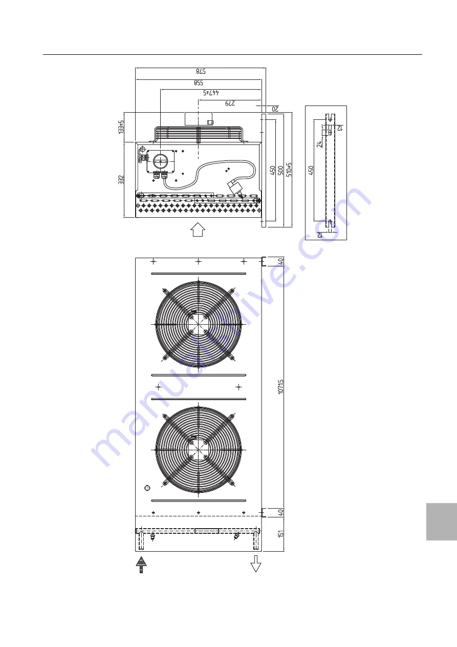
16 Further technical information
16
Fig. 73:
Standard condenser (facade mounting)
Страница 1: ...LCP Rack DX 12 LCP Inline DX 12 3311 410 420 3311 430 440 Assembly and operating instructions ...
Страница 2: ...cumentation carefully and pay particular attention to the safety instructions in the text and to section 2 Safety instructions This is the prerequisite for secure assembly of the LCP DX safe handling and the most trouble free operation possible Please keep the complete documentation readily availa ble so that it is always on hand when needed We wish you every success Your Rittal GmbH Co KG Rittal ...
Страница 3: ...P DX 19 5 2 7 Mounting the side panel 20 5 3 External condenser 20 6 Installation 22 6 1 General 22 6 2 Notes on pipework 22 6 3 Connecting the condensate discharge 25 6 4 Electrical connection 26 6 4 1 General 26 6 4 2 Connecting the LCP DX 26 6 4 3 Connecting the external condenser 27 6 5 Checking the entire system prior to commissioning 27 7 Operation 29 7 1 Control and display components 29 7 ...
Страница 4: ...lation prerequisites 55 15 3 Electrical heaters 55 15 3 1 General information 55 15 3 2 Activating the heaters 56 15 3 3 Technical specifications 56 15 4 Dehumidification 56 15 4 1 General information 56 15 4 2 Activating the dehumidification 56 15 4 3 Installation prerequisites 57 15 5 Condensate pump 57 15 5 1 General information 57 15 5 2 Technical specifications 57 15 5 3 Installation 57 15 6 ...
Страница 5: ...ure 1 5 Other applicable documents The general plant documentation for the room where the equipment is situated construction specifications for the ventilation system also applies in conjunction with these assembly and operating instructions 1 6 Normative instructions 1 6 1 Legal information concerning the operating instructions We reserve the right to make changes in content Rittal GmbH Co KG is ...
Страница 6: ... maintenance work Tie long hair back Do not wear loose clothing Fans start up automatically following power dis ruptions Danger Hot components may cause in jury In particular never touch the compres sor and cables while operational and for some time thereafter as they may still be hot Danger Risk of poisoning from coolant gases created under the influence of heat When carrying out welding and sold...
Страница 7: ...F2 and 50 R125 pen tafluoroethane C2HF5 3 Instructions for switching off the cooling system in an emergency see section 7 2 3 Switching off in an emergency 4 The maximum permissible pressures see section 11 Technical specifications 2 3 2 System log Under DIN EN 378 the operator is required to keep a system log and ensure that it is regularly updated The system log should contain the following info...
Страница 8: ...least every 12 months more than 500 t at 3 month intervals or where a leakage detection system is installed at least every 6 months 2 3 4 Chemicals Climate Protection Ordinance This Ordinance applies in addition to the aforementioned Regulation EC No 517 2014 of the European Parlia ment and of the Council of 16 April 2014 2 4 RoHS compliance The LCP DX fulfils the requirements of EU Directive 2011...
Страница 9: ...line DX is expelled to the front it is also possible to expel the cold air on both sides or by mounting a side panel at one side of the device Fig 1 Air routing on the LCP Rack DX top view Key 1 Air inlet 2 Heat exchanger 3 Air outlet 4 Fan module 5 2nd air inlet 6 2nd air outlet Fig 2 Air routing on the LCP Inline DX top view Key 1 Air inlet 2 Heat exchanger 3 Fan module 4 Air outlet The temperat...
Страница 10: ...ooling system with horizontal air routing It places no additional demands on the room s climate control system Fig 4 Air routing with a bayed server enclosure top view Key 1 Server enclosure 2 LCP Rack DX Fig 5 Air routing with two bayed server enclosures top view Key 1 Server enclosure 2 LCP Rack DX The system consisting of the LCP Rack DX and the serv er enclosure should be sealed as effectively...
Страница 11: ...ntain ment should be well sealed in order to avoid a decrease of the cooling capacity due to mixing of cold and hot air This is achieved by sealing the cold aisle with doors at the beginning and end of the rack rows and sealing it at the top with roof elements Existing cable entry glands are additionally sealed e g using suitable brush strips 3 3 Equipment assembly 3 3 1 Unit components Fig 7 LCP ...
Страница 12: ...urred is discharged into a conden sate collecting tray in the bottom section of the device Electronic expansion valve The expansion valve sup plies the evaporator coil with the required volume of coolant to provide the corresponding cooling output in the current ambient conditions External condenser The condenser is sited outdoors from the room where the LCP DX is situated Connec tion details for ...
Страница 13: ...imb of the user or third parties or result in possible damage to the system and other property Consequently the unit must only be used properly and in a technically sound condition Any malfunctions which impair safety should be rectified immediately Follow the operating instructions Proper usage also includes following the operating in structions and fulfilling the inspection and maintenance condi...
Страница 14: ...t to tipping Risk of top pling especially after the unit is removed from the pallet Caution Transport of the LCP DX without a pallet Use only suitable and technically sound lifting gear and load bearing devices with sufficient load capacity Note After unpacking the packaging materials must be disposed of in an environmentally friendly way They are comprised of the fol lowing materials Wood polyeth...
Страница 15: ...onnections required at the installation site 2 1 2 1 Position Distance Sum total of horizontal fig 11 item 1 and vertical spacing fig 11 item 2 or fig 12 item 2 between the LCP DX and the condenser Max 45 m equivalent length Condenser above LCP DX fig 11 item 2 max 20 m Condenser below LCP DX fig 11 item 2 max 3 m Tab 2 Distances and height differences Note When calculating the equivalent length p...
Страница 16: ... losses in the adjacent server racks If the LCP Inline DX is used in combination with server enclosures with high heat losses the number of LCP Inline DX units must be adapted according to the char acteristic curves The air temperature difference be tween server inlet and server outlet which is determined by the equipment used is particularly important As a rule of thumb a temperature difference o...
Страница 17: ...ounting rail of the server enclosure using an appro priate lever Loosen and remove the screws on both of the side panel mounting brackets top and bottom in the mid dle of the mounting rail Loosen and remove the screws from the 6 side panel holders on the side mounting rails 5 2 4 Seal the server enclosure In order to ensure targeted air routing in the system the server enclosure is vertically divi...
Страница 18: ...oam strips for devices with sideways air throughput top view LCP Rack DX Key 1 LCP Rack DX 2 Server enclosure 3 Foam strips on hot air side 4 Foam strips on cold air side If there is any surplus length of the foam strip on the server rack cut it off at the top edge of the rack On the side of the server enclosure opposite the LCP DX mount a side panel on the two side panel mountings Align it with t...
Страница 19: ...each other Dismantle the door of the LCP DX whose hinges are on the side on which the server enclosure is to be bayed Proceed as described in section 5 2 5 Dis mantle the server enclosure door Using the corresponding assembly screws fasten three baying connectors each fig 17 item 2 onto the attachment points provided in the mounting strips on the front and rear of the LCP DX fig 17 item 1 Fig 17 L...
Страница 20: ... firmly onto the side panel holders and the side panel mounting brackets 5 3 External condenser The installation site of the external condenser must be selected in such a way as to ensure an adequate supply and distribution of the airflow even in unfavourable con ditions see section 5 1 1 Installation site require ments To ensure ease of access to the external condenser for servicing purposes a su...
Страница 21: ... using the supports included with the supply of the device Fig 21 Horizontal or vertical mounting In the case of vertical mounting with a horizontal air flow the hot gas line must be laid above the liquid line Fig 22 Laying the hot gas and liquid lines Note Opening A must be at least as large as the front of the condenser ...
Страница 22: ...vent damage associated with routine activities For safety reasons and in order to protect the environ ment the following aspects should be taken into ac count when laying pipework 1 There must not be any threat to human safety i e escape and emergency vehicle routes must not be obstructed or restricted in any way When using re frigerants of groups A2 B1 B2 A3 or B3 no de tachable connections or fi...
Страница 23: ...ch as offices and meeting rooms 5 The gas line must be laid with an incline of 1 in the direction of flow of the coolant 6 A distance of at least 20 mm between the gas and the liquid line should be observed If this is not pos sible both lines should be adequately insulated 7 When laying out the refrigerant lines be sure no sag is created in which oil may collect install oil traps if necessary 8 Pr...
Страница 24: ... slugging hydraulic shock 5 Pipelines with detachable connections must not be positioned in public thoroughfares vestibules stair wells steps entrances exits or in ducts or shafts with unsecured openings to such areas unless pro tected against disconnection 6 Pipelines without detachable connections valves control and regulatory devices that are protected against accidental damage may be positione...
Страница 25: ...ess We recommend to inspect all connections for tightness including screwed joints by spraying with Nekal spray Evacuating 1 Upon successful pressure testing the air still re maining in the system must be removed To do so connect a vacuum pump and evacuate the system to a pressure of 0 3 mbar absolute pressure 2 If at all possible evacuate from both ends of the compressor that is from the intake a...
Страница 26: ...lways on hand when needed This is the only authoritative documentation for this unit Caution Work on electrical systems or equip ment may only be carried out by an elec trician or by trained personnel under the guidance and supervision of an electri cian All work must be carried out in ac cordance with electrical engineering regulations Contact with live electrical parts may be lethal The unit may...
Страница 27: ...Internally the con denser is fully wired and no connection is needed be tween the LCP DX and the external condenser via a data cable etc The fan speed of the condenser is con trolled via the system pressure Fig 29 Pressure switch on the condenser Key 1 Condenser 2 Pressure switch Power is supplied to the external condenser via a 3 wire connection cable 230 V 1 N PE The 3 wire cable must be inserte...
Страница 28: ...solder connections on pipe work for compliance with EN 14276 2 4 Check the refrigerant pipelines 5 Inspect the report on the cooling system leak test 6 Visually inspect the cooling system 7 Check the labels This inspection must be documented see EN 378 2 section 6 4 3 No cooling system may be operated with out the correct documentation The installer must document the fact that the system was insta...
Страница 29: ... the condenser at their re spective master switches 7 2 3 Switching off in an emergency To switch off the LCP DX and the condenser proceed as follows Switch off the LCP DX and the condenser at their re spective master switches 7 3 Layout of the user interface The user interface is divided into eight menu levels This level and where applicable the level below is displayed in the top right of every ...
Страница 30: ...ed param eter value Press the Up or Down button to change the pa rameter value to OFF Press the Return button to confirm the amended pa rameter value The device is now switched off Press the Esc button to move back to the start screen 7 6 2 Menu A02 A sleep mode may be activated in menu A02 As the LCP DX adapts to the required cooling output in any case settings are not generally required here 7 7...
Страница 31: ...The current values of the analog outputs are displayed in menu D13 7 9 4 Menu D14 The following parameters of the electronic expansion valve are displayed in an overview screen in menu D14 Superheat Degree of opening of the valve in Evaporation pressure Evaporation temperature Fig 34 Menu D14 7 9 5 Input output menu Other parameters of inputs and outputs are displayed in the input output menu The ...
Страница 32: ... IP address by activating the bootswitch parameters Activation is achieved by press ing the Reset button when booting up the card Switch on the LCP DX at the master switch Fig 36 pCO Web card Key 1 Controller 2 pCO Web card 3 Reset button 4 Ethernet cable Press the Reset button fig 36 item 3 if necessary with the assistance of a second person and keep it held down for around 20 seconds whilst the ...
Страница 33: ...ppear for logging on to the Web server Fig 38 Authentication on the pCO Web card Enter admin as the user and fadmin as the pass word Once you have successfully logged in the homepage of the pCO Web card will launch Fig 39 Homepage of the pCO Web card 7 13 3 Configure the network interface Network settings are made under the menu point Con figuration Network Here you can assign an IP address and up...
Страница 34: ...e controller by clicking on the Submit button Reboot to activate the changes 7 13 4 E mail configuration The parameters listed in the supervisory table see section 7 13 5 LCP DX supervisory table can be used to configure various events for notification by e mail The procedure for configuration is described in the original user instructions for the pCO Web card from Carel These instructions can be ...
Страница 35: ...ction tem perature C 99 9 99 9 R Customer 11 B11 probe value High pressure Compres sor Discharge Pressure bar 99 9 99 9 R Customer 12 B12 probe value Low pressure Compres sor Suction Pressure bar 99 9 99 9 R Customer 13 Evaporator temperature from Low pressure conversion C 99 9 99 9 R Customer 14 Condensing temperature from High pres sure conversion C 99 9 99 9 R Customer 15 20 Reserved not used o...
Страница 36: ...year 0 99 R Customer 13 Unit On Off 0 Off 1 On da ambiente 0 Off 1 On 2 Energy save 3 Auto 0 3 R W Customer 14 Envelope Zone 0 OK 1 Max compr ratio 2 Max disch P 3 Curr limit 4 Max suct P 5 Min compr ratio 6 Min DeltaP 7 Min disch P 8 Min suct P 0 9 R Only for Service Manufacturer 15 HT Zone 0 null 1 Disch T OK 2 Disch T inside control zone reduce speed rate 3 Disch T thr speed reduction 0 32767 R...
Страница 37: ...ternal debug 0 1 R Only for Service Manufacturer 23 Digital output 7 General Alarm Contact 0 1 R Customer 24 28 Reserved not used or other special appli cation or internal debug 0 1 R Only for Service Manufacturer 29 Command to reset all alarms by Supervisor 0 1 R W Only for Service Manufacturer 30 Envelope Alarm Memory alarm compressor forced off working out envelope 0 1 R Customer 31 Compressor ...
Страница 38: ...logic input B9 Compressor Discharge Temperature 0 1 R Customer 46 Memory alarm probe broken analogic input B10 Compressor Suction Temperature 0 1 R Customer 47 Memory alarm probe broken analogic input B11 Compressor Discharge Pressure 0 1 R Customer 48 Memory alarm probe broken analogic input B12 Compressor Suction Pressure 0 1 R Customer 49 99 Reserved not used or other special appli cation or in...
Страница 39: ...he er ror message will be deleted from the list The following additional information about the error mes sages will be output at the end of the aforementioned list of error messages 1 Sequence of error messages E01 is the oldest er ror E02 the one after that and so on 2 Date and time when the error occurred 3 The alarm code e g ALF01 4 A brief description of the cause of the error 5 Inlet and outl...
Страница 40: ...h erboard or replace the sensor ALA09 Alarms ALA09 Position B9 Probe B9 faulty or disconnected alarm Sensor failure or sensor not cor rectly connected Check the connection on the moth erboard or replace the sensor ALA10 Alarms ALA10 Position B10 Probe B10 faulty or disconnected alarm Sensor failure or sensor not cor rectly connected Check the connection on the moth erboard or replace the sensor AL...
Страница 41: ...am ALD02 Alarms ALD02 Probe S1 Probe S2 Probe S3 Probe S4 Sensor failure or sensor not cor rectly connected Check the connection on the moth erboard or replace the sensor ALD03 Alarms ALD03 EEV motor error Incorrect or missing wiring be tween motherboard and valve motor Check the connection on the moth erboard or replace on the valve mo tor ALD04 Alarms ALD04 Low superheat LowSH Incorrect coolant ...
Страница 42: ...eck the cable check previous high pressure alarm ALL99 99 Unexpected inverter stop Short power failure Restart the unit connect to a UPS if necessary After the reset the alarm is stored in the alarm data log as ALL01 ALW04 ALW04 Max temperature warning A previous alarm has stopped the unit heat load too high compared to the cooling capacity of the unit Reset the previous alarm Alarm code Display P...
Страница 43: ... a vacuum cleaner with the brush attachment to clean the heat exchanger 9 3 Fan installation If a fan module is defective it can be replaced quickly and easily with the unit operational Proceed as follows to remove a fan module Open the front door of the LCP DX On the electronics box deactivate the switch for the fan you wish to replace Fig 43 Electronics box front Key 1 Switch for fan 1 top fan i...
Страница 44: ...nce 9 44 Rittal Liquid Cooling Package Grasp the fan module with both hands on the left and right and pull it out of the rack Fig 45 Rotated fan module in fan tray Note The LCP DX may only be operated with all four fans running ...
Страница 45: ...tact us for advice Caution Risk of damage The LCP DX must not be subjected to temperatures above 50 C during stor age Caution Risk of environmental contami nation Never allow refrigerant from the cooling circuit or oil from the compressor to es cape into the environment Refrigerant and oil must be properly dis posed of in accordance with the valid national legislation and regulations ...
Страница 46: ...nnection clamp Rated voltage V Hz 380 480 V 10 3 N PE 50 60 Hz Rated current A 7 5 Startup current A 11 Pre fuse T A 20 Duty cycle 100 Cooling output Nominal cooling capacity EN 14511 kW L35 L35 9 0 L35 L30 12 0 Total power input kW L35 L35 4 0 L35 L30 4 0 Energy Efficieny Ratio EER L35 L35 3 0 Air throughput max m3 h 4 800 Cooling circuit Coolant Fill volume kg R410A see tab 23 Total refrigerant ...
Страница 47: ... max kg 29 Electrical connection Type of electrical connection Connection clamp Rated voltage V Hz 230 1 N PE 50 230 1 N PE 60 Startup current A 2 3 2 1 Pre fuse T A 6 6 Duty cycle 100 Cooling circuit Coolant Fill volume kg R410A see tab 23 Total refrigerant charge Connection diameter refrigerant pipes mm See tab 24 Refrigerant pipes External diameter of coolant lines mm See tab 24 Refrigerant pip...
Страница 48: ...t Fill volume kg R410A see tab 23 Total refrigerant charge Connection diameter refrigerant pipes mm See tab 24 Refrigerant pipes External diameter of coolant lines mm See tab 24 Refrigerant pipes 1 mm wall thickness Other information Storage temperatures C 40 50 Ambient temperature C 40 45 Noise level dB A Open air above reflective flooring distance 10 m 43 Tab 20 Technical specifications for the ...
Страница 49: ...th x height x depth mm 2282 x 818 x 552 Weight max kg 68 Electrical connection Type of electrical connection Connection clamp Rated voltage V Hz 230 1 N PE 50 230 1 N PE 60 Startup current A 3 2 8 Pre fuse T A 6 6 Duty cycle 100 Cooling circuit Coolant Fill volume kg R410A see tab 23 Total refrigerant charge Connection diameter refrigerant pipes mm See tab 24 Refrigerant pipes External diameter of...
Страница 50: ...tre above 5 m kg System with standard condenser 2 8 0 03 System with low temperature condenser and winter kit module 4 8 0 03 System with high temperature condenser 2 65 0 03 Tab 23 Total refrigerant charge Type of condenser Connection diameter condenser liquid line hot gas line mm Equivalent length External diameter of coolant lines liquid line hot gas line mm Standard 22 22 Up to 45 m 12 12 Low ...
Страница 51: ... 12 12 Spare parts Article Qty Pack Control unit 1 Display 1 Compressor 1 Inverter 1 Electronic expansion valve 1 Fan single 1 Switch for fan 1 High pressure switch 1 Temperature sensor hot cold air 1 Coolant filter 1 Tab 25 Spare parts list LCP DX ...
Страница 52: ...e width 600 mm for external mounting on LCP DX 3301 370 1 Vertical shielding foam strips for enclosure width 800 mm for external mounting on side panel 3301 390 1 Vertical shielding foam strips for enclosure width 800 mm for external mounting on LCP DX 3301 320 1 Air baffle plate for TS for enclosure width 600 mm 7151 206 2 Air baffle plate for TS for enclosure width 800 mm 7151 208 2 Add on cover...
Страница 53: ...Evaporation Pressure Condensation Pressure Setpoint Fans Speed Electronic Valve Opening Compressor Inverter Speed Compressor Motor Current The following parameters are displayed in diagrammatic form on the LCP DX homepage Setpoint speed for the fans Server in temperature top middle bottom Server out temperature top middle bottom Position of the electronic expansion valve Compressor speed The 2nd m...
Страница 54: ...d the humidifier is activated only when required 15 2 2 Activating the humidifier To activate the humidification function proceed as fol lows Assign the YES value to the Enable B5 humidity entry in the Hc39 menu Fig 49 Hc39 menu Also assign the YES value to Enable entry in the Ha35 menu Fig 50 Ha35 menu 15 2 3 Setting the humidity setpoint DIP switches located below the humidifier allow the de sir...
Страница 55: ...ctrical heaters The deployed 2 kW heaters are switched on automati cally by the LCP DX controller when the average value of the air temperature falls below a specified setpoint In case of Room operating mode the air temperature is the return air from the servers while for Rack and Water supply pressure range 0 1 6 bar Water supply flow rate 0 6 l min Water supply Demineralised water Discharge flow...
Страница 56: ...ermal protection of the electri cal heaters 15 3 3 Technical specifications 15 4 Dehumidification 15 4 1 General information At installation locations where high humidity generally prevails there is the danger that water condenses inside the IT cabinet This can cause short circuits and other damage to the installed devices Excessive humidity can also lead to rust and corrosion To prevent this the ...
Страница 57: ...menu 15 4 3 Installation prerequisites Any condensate that occurs is then fed to the conden sation tray Ensure that the condensate discharge is installed cor rectly see section 6 3 Connecting the condensate discharge Alternatively connect the optional condensate pump see section 15 5 Condensate pump 15 5 Condensate pump 15 5 1 General information If the condensate or water from the humidifier cann...
Страница 58: ...be operated at outdoor temperatures as high as 45 C If this maximum temperature is overshot to maximum 53 C the optional high temperature condenser that replaces the 3311 360 standard unit must be deployed For the above mentioned maximum temperature the maximum cooling capacity with the optional condenser is 7 55 kW 15 7 2 Installation prerequisites Note the larger dimensions of the high temperatu...
Страница 59: ...15 9 2 Installation Connect the operating and display elements for a maximum of eight LCP DXs using a twin core cable Note that the maximum cable length from the first LCP DX to the last LCP DX must not exceed 100 m 15 9 3 Activating the redundancy Assign the YES value to the Enable rotation entry to all LCP DX devices of the group in the Ha11 menu Fig 61 Ha11 menu The following settings are displ...
Страница 60: ...oling Package Fig 63 Debug menu 15 9 4 Installation prerequisites No additional software is required for redundancy oper ation For previously installed devices it must be guar anteed that the correct version of the software is pres ent ...
Страница 61: ...operating data Exterior temperatures between 5 C and 42 C Cooling output from 3 kW to 12 kW in 3 kW incre ments Setpoint temperature 22 C for the LCP Inline DX Rack DX Exterior temperature 5 C Fig 64 Diagrammatic view Caution The LCP DX may only be operated with coolant R410A Use of any other coolant will invalidate the guarantee Caution Risk of malfunction or damage Installation and in particular...
Страница 62: ...3 6 9 12 Inlet temperature C 25 43 27 45 29 07 32 83 Outlet temperature C 21 86 21 5 21 19 23 2 dT C 3 57 5 95 7 88 9 63 Output kW 0 777 1 627 2 717 4 142 Tab 36 Tabular view 0 10 20 30 40 0 2 4 6 8 10 12 0 10 20 30 40 0 2 4 6 8 10 12 Exterior tempera ture C 30 Cooling output kW 3 6 9 12 Inlet temperature C 25 56 27 59 28 91 33 28 Outlet temperature C 21 89 21 56 21 16 23 6 dT C 3 67 6 03 7 75 9 6...
Страница 63: ...t very low exterior temperatures of 20 C and very low cooling outputs of 2 kW and 4 kW Exterior tempera ture C 45 Cooling output kW 3 6 9 9 76 Inlet temperature C 25 63 26 55 28 39 30 35 Outlet temperature C 22 08 19 87 20 23 22 04 dT C 3 55 6 68 8 16 8 31 Output kW 1 084 2 258 4 182 4 676 Tab 39 Tabular view Exterior tempera ture C 20 Cooling output kW 2 4 Inlet temperature C 26 08 Outlet tempera...
Страница 64: ...51 Rear view Inline Rear view Rack Rear view without door Side view Front view Rear door Inline Rear door Rack Side panel right Cover plate for perforated area rear Punched area 244x1760 Punched area 126x1803 View from above Scale 1 3 Electrical box Fan Front door Roof plate for optional pipe entry from top View from below Scale 1 2 100 5 51 25 44 75 207 5 44 75 1108 99 38 5 56 195 5 76 103 5 ...
Страница 65: ...k Rear view without door Side view Front view Rear door Inline Rear door Rack Side panel right Cover plate for perforated area rear Punched area 244x1760 Punched area 126x1803 View from above Scale 1 3 Electrical box Fan Front door Roof plate for optional pipe entry from top View from below Scale 1 3 64 65 75 44 75 207 5 44 75 189 5 1310 76 146 2005 1528 8 67 180 29 78 5 83 5 ...
Страница 66: ...16 Further technical information 16 66 Rittal Liquid Cooling Package Fig 72 Standard condenser console installation ...
Страница 67: ...Rittal Liquid Cooling Package 67 16 Further technical information 16 Fig 73 Standard condenser facade mounting ...
Страница 68: ...16 Further technical information 16 68 Rittal Liquid Cooling Package Fig 74 Installation diagram of the high temperature condenser 2282 818 ...
Страница 69: ...Rittal Liquid Cooling Package 69 16 Further technical information 16 Fig 75 Refrigerant scheme low temperature unit ...
Страница 70: ...16 Further technical information 16 70 Rittal Liquid Cooling Package Fig 76 Installation scheme low temperature condenser Low temperature unit ...
Страница 71: ...Rittal Liquid Cooling Package 71 16 Further technical information 16 Fig 77 Installation scheme winter kit module Low temperature unit ...
Страница 72: ...FANS 1 4 POWER SUPPLY X26 1 2 3 4 FANS 1 4 0 10VDC INPUT M1 M4 FANS M5 COMPRESSOR F1 F2 BREACKER SWITCHES S1 S4 FANS THERMIC SWITCHES U1 COMPRESSOR DRIVE LX CHOKE G1 POWER SUPPLIER 400 460VAC 24VDC EEV ELECTRONIC EXPANSION VALVE PA PRESSURE SWITCH B2 B3 B4 AIR INPUT TEMPERATURE PROBES B6 B7 B8 AIR OUTPUT TEMPERATURE PROBES B9 COMPRESSOR DISCHARGE TEMPERATURE PROBE B10 COMPRESSOR SUCTION TEMPERATUR...
Страница 73: ...Rittal Liquid Cooling Package 73 16 Further technical information 16 16 5 Piping and instrumentation diagram to DIN EN 1861 1998 Fig 79 Piping and instrumentation diagram to DIN EN 1861 1998 ...
Страница 74: ...16 Further technical information 16 74 Rittal Liquid Cooling Package Fig 80 Parts list piping and instrumentation diagram ...
Страница 75: ...le Under this cooling principle cold air supplied by exter nal air conditioning is blown to the front of the server enclosure The fans in the devices built into the server enclosure direct this air horizontally through the server enclosure The air is warmed through this process and is exhausted out of the rear of the enclosure Fig 81 Front to back cooling principle with bayed LCP Rack Hotspot A ho...
Страница 76: ...rvice addresses For technical questions please contact Tel 49 0 2772 505 9052 E mail info rittal de Homepage www rittal com For complaints or service requests please contact Tel 49 0 2772 505 1855 E mail service rittal de Rittal GmbH Co KG Auf dem Stützelberg 35745 Herborn Germany ...
Страница 77: ......
Страница 78: ...tructure Software Services You can find the contact details of all Rittal companies throughout the world here www rittal com contact RITTAL GmbH Co KG Auf dem Stuetzelberg 35745 Herborn Germany Phone 49 2772 505 0 E mail info rittal de www rittal com 11 2019 ...