background image


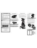
Accessories Supplied 


Bracket 

 
2pcs 


Screws 

 
4pcs 


Sealing strip 

 
1pc 

 
Built-in appliance 


Fit the appliance in a suitable cabinet to ensure that 
the appliance functions properly. 


Observe the minimum installation height from hob 
to 

cooker 

hood 

(see 

the 

cooker 

hood 

manufacturer’s  instruction  manual  for  details).  If 
the manufacturer’s instructions are not available, a 
safety  distance  of  minimum  500mm  must  be 
maintained. 


Cabinets with a veneer exterior must be assembled 
with glues which can withstand temperatures of up 
to 100

0

C. 


The cabinet must have the cut-out dimensions. See 
‘Technical Specifications’ in this manual. 


If the appliance is to be installed above an oven, the 
oven  must  be  equipped  with  a  cooling  ventilation 
system.


We  do  not  recommend  installing  the  hob  above  a 
fridge,  freezer,  dishwasher,  washing  machine  or 
dryers. If this cannot be avoided, ensure that there 
is  waterproof  separation  between  the  two 
appliances. 

 
Ventilation 

Do  ensure  adequate  ventilation  to  avoid  overheating 
the appliance and surrounding surfaces.  


We  recommend  a  safety  distance  of  minimum 
60mm from hob cut-out to back wall, and minimum 
70mm from hob cut-out to side wall.  


Maintain  a  minimum  distance  of  45mm  between 
the underside of hob and the cabinet underneath. 


If hob is installed above an oven, allow a minimum 
distance of 30mm from the underside of the hob to 
top of an oven. 


Fixing the appliance 

Ensure  that  the  hob  is  installed  on  a  flat  and  supporting 
surface.  Any  deformities  to  the  appliance  caused  during 
improper installation could affect the hob operation. 


Fix  the  2(two)  L-shaped  brackets  using  4(four)  screws 
supplied.  Observe  the  bracket  installation  distance  as 
shown in installation cut-out drawings. 


Stick the sealing strip (provided) on the underside of  
the hob around the outside edge (see inlet). Be careful 
not to stretch the sealing strip. 


Place  the  hob  centrally  in  the  installation  cavity  and 
secure  the  hob  firmly  to  the  bracket  using  4(four) 
screws provided. Ensure that the sealing strip secured 
on underside of hob edges is in place. 


Make the electrical connection and connect to power 
supply. 


Check that the hob operates normally. 


INSTALLATION 

Installation by qualified persons  only.  The  manufacturer  declines all responsibility for  improper installation and does 
not accept responsibility for appliance warranty in the event of damage caused by incorrect installation. 


Never  glue  or  silicone  the  appliance  unit  to  the 
installation  cavity.  The  appliance  must  be  easily 
removed out of the cavity for servicing or repair. 

En

gl

ish


Содержание RB-3002E-CB

Страница 1: ...ation Manual Petunjuk Pemakaian Pemasangan Ho t ng H ng d n l p t Vitroceramic Electric Hob Kompor Listrik Keramik B p m i n RB 3002E CB RB 6004E CB RB 7003E CBM Rinnai Corporation English Bahasa Indo...

Страница 2: ...English Page 1 9 10 18 Bahasa Indonesia Hal 19 27 Ti ng Vi t Trang 28 36 37 44 TABLE OF CONTENTS...

Страница 3: ...n 6 Maintenance and care 8 Troubleshoot 8 Installation 9 CONTENTS Version 2013 03 IMPORTANT Please paste the serial number labels enclosed with the packaging on your warranty card to register your pro...

Страница 4: ...y may cause damage to the hob surface Do not use if appliance is faulty or cooktop is cracked to avoid possibility of electric shock Contact a qualified technician immediately for repair and service T...

Страница 5: ...t right 1200W 150mm Front Left 2200W 215mm Front Right 1800W 185mm Back Centre 1200W 150mm Total power 3000W 6400W 5200W Appliance dimension 288 W x 510 D x 50 H mm 596 W x 510 D x 50 H mm 700 W x 430...

Страница 6: ...ngle circle zone 1200W 150mm Control panel Double circle zone 2200W 215mm Single circle zone 1200W 150mm Single circle zone 1800W 185mm Control panel Single circle zone 2000W 185mm Single circle zone...

Страница 7: ...er Level Control 1 ON OFF key with power indicator 2 Cooking zone selection 3 Power level indicator 4 Power level selector to increase level 5 Power level selector to decrease level 6 Child lock key w...

Страница 8: ...r lamp is displayed To deactivate press and hold the child lock key The indicator light goes off If no function is selected within 3 minutes in operation the child lock hob is activated automatically...

Страница 9: ...ons on the glass ceramic surface and are difficult to remove or may leave permanent stains To obtain best results Cookware with thick and flat bases should be chosen for the benefit of uniform heat di...

Страница 10: ...switch is turned on and the plug is properly inserted in the electrical outlet The hob gives off a smell when used for the first time This is a normal occurrence See Using for the first time in this...

Страница 11: ...minimum distance of 45mm between the underside of hob and the cabinet underneath If hob is installed above an oven allow a minimum distance of 30mm from the underside of the hob to top of an oven Fixi...

Страница 12: ...connector with earth that is correct for your location The electrical connection of this appliance must be connected to earth where applicable Green Yellow EARTH Blue NEUTRAL Brown LIVE The socket can...

Отзывы: