background image


34 

Rinnai Corporation EX17C / EX22C Manual 


Parts 

List     


For replacement parts call Rinnai at 1-800-621-9419. 


Содержание Energysaver EX17C

Страница 1: ...AI1 746 6241 WARNING If the information in these instructions is not followed exactly a fire or explosion may result causing property damage personal injury or loss of life Do not store or use gasoline or other flammable vapors and liquids in the vicinity of this or any other appliance WHAT TO DO IF YOU SMELL GAS Do not try to light any appliance Do not touch any electrical switch do not use any p...

Страница 2: ...Saving Mode 9 Set back 10 Humidifier and Airflow Direction 10 Adding Water to the Humidifier 10 Adjusting Air Flow Direction 10 Care and Maintenance 11 Maintenance 11 Care of Exterior 11 Snow Accumulation 11 Filters 11 Visual Inspection of Flame 11 Before Making a Service Call 12 Fault Codes 13 Restart Function 14 Troubleshooting 14 Installation Instructions General Instructions 15 Gas Connection ...

Страница 3: ...louvers Do not spray aerosols near the appliance while it is operating Most aerosols contain butane gas which is flammable Do not unplug the appliance while it is operating or while the fans are on Do not use bare hands to touch the front louvers due to high temperatures which may cause burns Prevent dust from accumulating on the power cord side covers and parts behind the appliance Do not sit on ...

Страница 4: ...s AC 120V 60 Hz 56 watts Standby Power 0 5 watt Weight Noise Level 33 38 dB 33 42 dB AFUE Rating Natural Gas 81 Propane 82 Natural Gas 80 Propane 82 57 lbs 26 kg Specifications Rinnai is continually updating and improving products Therefore specifications are subject to change without prior notice The efficiency rating of this appliance is a product thermal efficiency rating determined under conti...

Страница 5: ...r Level keeps your feet warm Child Lock Room Temperature Setting Memory Clean the Air Filter Indicator Lamp Energy Saving Economy Setting Humidifier Tray Air Flow Directional Louvers Direct Vent Easily Installed Proportional Heating Variable Capacity Hush Quiet Operation Modern Design Minimizes Floor Space Requirements Fault Code Message Display Timers 1 and 2 Dimmer Set back setting a minimum tem...

Страница 6: ...L WARM AIR OUTLET BOTTOM COVER HOLD BOTH SIDES AND PULL TOWARD YOU CONTROL PANEL RATING PLATE MODEL NUMBER SERIAL NUMBER GAS TYPE ETC ENGLISH IS ON THE RIGHT FRENCH IS ON THE LEFT ROOM TEMPERATURE SENSOR THERMISTOR POWER CORD PLUG 120V AC 60 Hz AIR FILTER EXHAUST PIPE COMBUSTION AIR INTAKE HOSE VENT TERMINAL COMBUSTION AIR EXHAUST GAS CONNECTION 1 2 MALE NPT ...

Страница 7: ...perature thermistor when the heating starts the heating capacity is automatically adjusted to achieve a comfortable heating effect and to reach the temperature setting quickly Occasionally the room temperature may briefly exceed the temperature setting due to the layout of the room or heating area ON OFF Press the ON OFF button to operate the heater The ON indicator will glow green Once the burner...

Страница 8: ...the up or down arrows to set the start time Holding down either of the arrow keys will change the time more quickly 3 Press the Set Times button again so that the Timer 1 off position is lit Press the up or down arrows to set the end time Holding down either of the arrow keys will change the time more quickly 4 Press the Set Times button again to set the times for Timer 2 Follow the same steps abo...

Страница 9: ...omy mode on press the Economy button The Economy indicator is lit The Economy mode now remains in the system memory If the appliance is turned off manually or stops heating as a result of an OFF timer period the Economy indicator will go out Whenever the appliance starts heating again the Economy indicator will light 2 To turn the Economy mode off press the Economy button The Economy indicator wil...

Страница 10: ...e bottom panel Do not operate the appliance unless the humidifier tray is installed During operation a small amount of condensation is produced in the flue system and drains into the humidifier tray This function allows a minimum room temperature to be pre set between 38ºF and 78ºF in 2ºF increments This temperature should be set below the room temperature setting The default setting is 60ºF Once ...

Страница 11: ...2 Remove the front panel by removing five screws 3 Use pressurized air to remove dust from the main burner heat exchanger and fan blades 4 Use soft dry cloth to wipe cabinet Do not use wet cloth or spray cleaners on the burner The flue should be inspected annually for blockages or damage Motors are permanently lubricated and do not need periodic lubrication Keep fan and motor free of dust and dirt...

Страница 12: ...ng the outlet for the hot air Is the flue blocked The fan is started automatically after a short delay This is to allow the heat exchanger to warm up helping to avoid cold draughts This is caused by grease or oil and dust on the heat exchanger and will stop after a short time This is simply expansion noise from the heat exchanger This is the sound of the solenoid gas valves opening and closing Is ...

Страница 13: ...breaks to shut off the appliance 3 Remove any obstructions The flue needs to be kept clear to expel exhaust gases If the appliance fails to operate contact a qualified service agency CODE DISPLAYED FAULT REMEDY 11 1 Ignition Failure Check that gas is turned ON Check that the vent termination is not blocked Refer to the Restart Function explanation Service call if repeated 14 Overheat Clean filter ...

Страница 14: ...about 15 seconds before ignition After this time the temperature control logic controls the combustion If the flame is extinguished burner combustion failure while the temperature control logic is operating the appliance then the appliance will immediately attempt ignition No fault code will appear Problem Remedy Cause Not Plugged In Power Failure Initial Installation Air In Gas Pipe Gas Filter Bl...

Страница 15: ...used This appliance discharges a large volume of warm air next to the floor Any particles in the air such as cigarette smoke could cause discoloration in carpet The warm air flow could discolor nylon carpets containing dyes or vinyl surfaces To prevent discoloration of the floor covering a mat may be placed under the appliance which extends about 30 inches 750 mm in front of it Wood is included in...

Страница 16: ...ions including soap and water may cause corrosion or stress cracking the piping shall be rinsed with water after testing unless it has been determined that the leak test solution is non corrosive Check the gas supply pressure immediately upstream at a location provided by the gas company Supplied gas pressure must be within the limits shown in the Specifications section Refer to an approved pipe s...

Страница 17: ... EX17C EX22C Manual 17 Dimensions A full size template is provided on the cardboard packaging DO NOT DISCARD until installation is completed NOTICE 10 1 in 257 mm 3 3 in 85 mm 6 8 in 172 mm 29 9 in 760 mm 22 9 in 582 mm ...

Страница 18: ...earances X V AIR SUPPLY INLET VENT TERMINAL AREA WHERE TERMINAL IS NOT PERMITTTED INSIDE CORNER DE TAIL FIXED CLOSED OPERABLE FIXED CLOSED OPERABLE B B B A J B M C F B B E D L G A H K I SNOW TERMINATION Clearance in Ref A also applies to anticipated snow line ...

Страница 19: ...learance to ventilated soffit located above the terminal within a horizontal distance of 2 feet 61 cm from the center line of the terminal E Clearance to unventilated soffit F Clearance to outside corner G Clearance to inside corner 20 inches 50 cm 20 inches 50 cm H Clearance to each side of center line extended above meter regulator assembly 3 feet 91 cm within a height 15 feet 4 5 m above the me...

Страница 20: ...51 Back Spacer Set Pipe Stopper A Ring Plastic tie for air inlet Plastic tie L 250mm Screw M4 8 32 Wood Screw 1 1 1 1 1 3 5 1 4 4 M4 Screw M4 Screw M4 Wall Bracket Spacer Bracket 1 1 For Back Spacer Set For Flue Manifold For Spacer Bracket Wall Bracket Screws The following items are included with the appliance Installation Parts A Vent Kit FOT 151 This plastic tie should be located here ...

Страница 21: ...e diagram For weatherboard walls drill through the center of the weatherboard from the outside first and then through the plasterboard A template is provided For installation without using extension kits the configuration of the flue manifold air intake hose and exhaust slide pipe should be as shown when installation is completed The shaded area shows where the flue manifold can be located Configu...

Страница 22: ...beyond the red line For other than the S type flue manifold if a shorter length is necessary an extension can be removed Cut the outer plastic laminate with a utility knife or similar and remove the extension The metal should not be cut The flue manifold must exhaust to the outside Do not exhaust into other rooms The flue manifold is not designed to be positioned under floors or below the heater T...

Страница 23: ...nnection Assembly Push the assembly into the terminal tube ensuring that the seal is in place on the inner tube Attach the inside connection with 3 screws The inner connection can still be turned to install the screws 4 Install the Terminal Check that the terminal seal is in place For weatherboard walls add the second seal next to the terminal seal to compensate for weather board angle From the ou...

Страница 24: ...xtend the exhaust line and air intake hose between the manifold and the appliance 1 The maximum vent length is 13 feet 4 m with 2 bends The bent pipe attached to the appliance does not count toward the max limit of 2 bends 2 Maximum vertical length allowed is 10 feet 3 m 3 If the extension is longer than 10 feet 3 m the condensate may overflow the condensation pan Therefore extension exceeding thi...

Страница 25: ...st pipe Use the adjustable pipes if necessary To bend the elbow insert exhaust pipes into both ends for additional leverage Bend to desired angle Do not straighten the bent pipe attached to the appliance Pipe stopper A Pipe stopper B Male end Female end Adjust the angle Connecting the Air Intake Hose The air intake hose is connected between the air connection at the rear of the heater and the air ...

Страница 26: ...750 mm 1 3 Air Intake Hose 49 2 in 1 25 m 1 3 Air Intake Hose 90 6 in 2 3 m 1 4 Bent Elbow 1 5 Long Bent Elbow 1 6 Hose Joint 1 1 1 7 Pipe Stopper A 1 1 2 1 1 8 Pipe Stopper B 1 1 1 9 Pipe Clamp 2 sets 3 sets 4 sets 10 Wall Fixture 2 3 4 11 Nut 2 3 4 12 Screw A 2 3 4 13 Screw B 4 6 8 FOT 201 1 1 1 1 Extension Kits and Parts EXHAUSTPIPE ADJUSTABLE EXHAUSTPIPE NONADJUSTABLE AIRINTAKEHOSE BENTELBOW L...

Страница 27: ...eeve up to the flue manifold and slip the securing clip over the sleeve as shown 5 Install the bracket on the rear of the top spacer by tightening 2 screws 6 Install the wall bracket with two screws Attach the heater to the wall bracket with 2 screws Flue Manifold a b Fit Clip Slide Sock Top Spacer Spacer bracket Top Spacer Wall bracket Wall Bracket Top Spacer Spacer Bracket 1 Attach the air inlet...

Страница 28: ...oard are supplied with 120 volts AC CAUTION Do not touch the areas at or near the exhaust These areas become very hot and could cause burns Pressure Point Pressure Point Nozzle Manifold Test Switch Natural Gas Propane Gas Altitude 0 2000 ft 0 610 m 2001 5200 ft 611 1585 m 5201 7700 ft 1586 2347 m 7701 10200 ft 2348 3109 m 0 2000 ft 0 610 m 2001 5200 ft 611 1585 m 5201 7700 ft 1586 2347 m 7701 1020...

Страница 29: ...r and install Allen head screws Operate the unit and 1 Install the front panel and bottom cover 2 If doing a gas type conversion place the new conversion plate label on the front cover Check that the burner flames are operating normally The flame can be seen through the circular window When operating normally the burner flame should appear as long clear blue stable streaks Yellow flames or an oran...

Страница 30: ...d any gas control which has been under water TO TURN OFF GAS TO APPLIANCE 1 Set the thermostat to lowest setting 2 Turn off all electric power to the appliance using the ON OFF button on the control panel 3 Locate the manual gas valve on the side of the unit Turn the manual valve clockwise to the full OFF position NOTE The fan will continue to operate until the appliance is cool Do not turn the ap...

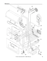
Страница 31: ...Rinnai Corporation EX17C EX22C Manual 31 Cut Away Diagram ...

Страница 32: ...an cause improper and dangerous operation CAUTION CODE COLOR bk black bl blue gr green gr y green yellow r red w white y yellow gy gray or orange br brown MARK PART NAME MS MAIN SWITCH R TH THERMISTOR TF THERMAL FUSE F FUSE ER ELECTRODE POV MODULATING SOLENOID VALVE TR TRANSFORMER FR FLAME ROD MARK PART NAME OH TH OVER HEAT THERMISTOR OHS1 2 OVER HEAT SWITCH 1 2 FM CONVECTION FAN MOTOR SP SPARKER ...

Страница 33: ...ELECTRODE POV MODULATING SOLENOID VALVE TR TRANSFORMER FR FLAME ROD MARK PART NAME OH TH OVER HEAT THERMISTOR OHS1 2 OVER HEAT SWITCH 1 2 FM CONVECTION FAN MOTOR SP SPARKER SV1 2 MAIN SOLENOID VALVE 1 2 BL COMBUSTION FAN MOTOR FCC FAN CONTROL CIRCUIT MB MAIN BURNER PS PRESSURE SENSOR CPU CENTRAL PROCESSING UNIT CF CONVECTION FAN ...

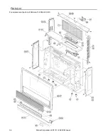
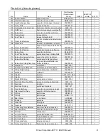
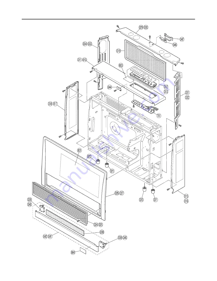
Страница 34: ...34 Rinnai Corporation EX17C EX22C Manual Parts List For replacement parts call Rinnai at 1 800 621 9419 ...

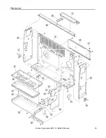
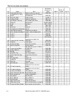
Страница 35: ...Rinnai Corporation EX17C EX22C Manual 35 Parts List ...

Страница 36: ...36 Rinnai Corporation EX17C EX22C Manual Parts List ...

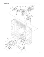
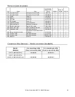
Страница 37: ...Rinnai Corporation EX17C EX22C Manual 37 Parts List ...

Страница 38: ...38 Rinnai Corporation EX17C EX22C Manual Parts List ...

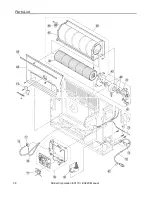
Страница 39: ...Rinnai Corporation EX17C EX22C Manual 39 Parts List ...

Страница 40: ...ng Bracket Parenthèse de fixation de plancher 308F 454 2 2 2 023 Heat Exchanger Packing enveloppe d échangeur thermique 554F 421 2 1 1 1 024 Louver Assy B ensemble de persiennes B 208000040 1 1 025 Louver Assy ensemble de persiennes 208000041 1 026 Front Panel B panneau frontal B 209000106 1 1 027 Front Panel panneau frontal 209000107 1 028 Heat Shield Panel panneau écran thermique 209000108 1 1 1...

Страница 41: ... 1 1 1 116 Damper G amortisseur 556F 209 7 1 1 1 117 Secondary Air Damper A amortisseur à air secondaire 206000016 1 1 1 118 Fitting Plate Packing garniture de plaque de fixation 206000017 1 1 1 119 Manifold collecteur 206000038 1 1 1 120 Injector injecteur AU129 210 0 85 4 4 4 120 Injector injecteur 206000018 4 4 4 121 Manifold Packing garniture de collecteur 556F 203 2 1 1 1 122 Electrode Mounti...

Страница 42: ...or moteur de convection 208000047 1 1 1 403 Motor Fixing Plate socle de moteur 209000126 1 1 1 404 Convection Fan Blade Assemblée de pale de ventilateur de convection 208000048 1 1 1 405 Casing Assembly enveloppe 208000049 1 1 1 406 Bearing roulement RC 223 74 1 1 1 407 Humidifier Tray bac d humidificateur 556F 309 1 1 1 408 Heat Shield Board Assy plaque écran thermique 209000127 1 1 1 409 Seal jo...

Страница 43: ... 718 Sensor Lead Assy assy de fil de sonde 1004F 2053 1 1 1 800 Water Line Label ligne de flottaison étiquette 550F 1418 1 1 1 801 Operation Label étiquette d opération 200000059 1 1 1 802 Power Supply Cord label étiquette de corde d alimentation d énergie 431F 1860 1 1 1 803 Caution Label étiquette d attention 431F 1830 1 1 1 804 Caution Label étiquette d attention RHF559 1240 1 1 1 808 Manual ma...

Страница 44: ...must be genuine Rinnai parts All repairs or replacements must be performed by an individual or servicing company that is properly trained state qualified or licensed to do the type of repair Item Period of Coverage Heat Exchanger 10 years from date of purchase All Other Parts 5 years from date of purchase Reasonable Labor 2 years from date of purchase The installer is responsible for your heater s...

Страница 45: ...res or operating difficulties due to the following accident abuse or misuse alteration misapplication force majeure improper installation such as but not limited to condensate damage improper venting incorrect gas type or incorrect gas pressure improper conversion including conversions for inventory adjustment improper maintenance such as but not limited to vent blockage incorrect sizing any other...

Страница 46: ...e ou d autres vapeurs ou liquides inflammables à proximité de cet appareil ou de tout autre appareil QUE FAIRE SI VOUS SENTEZ UNE ODEUR DE GAZ Ne pas tenter d allumer d appareil Ne toucher à aucun interrupteur ne pas vous servir des téléphones se trouvant dans le bâtiment Appeler immédiatement votre fournisseur de gaz depuis un voisin Suivre les instructions du fournisseur Si on ne peut pas joindr...

Страница 47: ...nfants 52 Mise à l heure 53 Utilisation manuelle du chauffage 53 Réglage et utilisation des minuteries 53 Fonction de surpassement 54 Économie Mode de conservation d énergie 54 Programmation de température minimale 55 Humidificateur et la direction du flux d air 55 Soins et entretien 56 Avant d appeler pour de l aide 57 Codes de défauts 58 Fonction de redémarrage 59 Dépannage 59 Instructions d ins...

Страница 48: ...lessures graves voire mortelles Indication d une situation potentiellement dangereuse qui si elle n est pas évitée peut entraîner des blessures légères ou moyennes On peut également l utiliser pour signaler des pratiques non sûres DANGER ATTENTION Ne bloquez pas l évacuation de l air chaud Ne laissez personne dormir directement en face de l appareil Du fait de ses températures élevées l appareil d...

Страница 49: ... et coupe l appareil EX17C EX22C Application Pour maison préfabriquée USA uniquement ou maison mobile ou installation résidentielle convertible pour utilisation au gaz naturel ou de pétrole liquéfié quand les mesures de conversion nécessaires ont été prises pour passer d un gaz à l autre Pour exploitation commerciale Pour l installation de 10 200 ft 3109 m Description générale Chauffage au gaz à c...

Страница 50: ...nheit Spécifications de l appareil Gaz naturel Gaz propane Pression d alimentation en gaz min 3 5 in 89 mm W C 8 0 in 203 mm W C Pression d alimentation en gaz max 10 5 in 267 mm W C 13 0 in 330 mm W C Gaz naturel Gaz propane BTU par heure en entrée Basse 8200 Haute 16700 Basse 8200 Haute 16700 BTU par heure en sortie Basse 6560 Haute 13360 Basse 6560 Haute 13360 EX17C Consultez les instructions d...

Страница 51: ...OUR REGARNIR SORTIE D AIR CHAUD COUVERCLE DU BAS TENIR LES DEUX CÔTÉS ET TIRER VERS VOUS AFFICHAGE PLAQUE SIGNALÉTIQUE RÉFÉRENCE DE MODÈLE N DE SÉRIE TYPE DE GAZ ETC THERMISTANCE FICHE PLUG 120V AC 60 Hz FILTRE À AIR CONDUITE D ÉVACUATION TUYAU D ADMISSION D AIR DE COMBUSTION TERMINAISON DE VENTILATION COMBUSTION ÉVACUATION CONNEXIONS DE GAZ 1 2 mâle NPT ...

Страница 52: ...t seront bloquées S il est activé pendant que le chauffage est à l arrêt toutes ses commandes seront bloquées Si le chauffage a été arrêté pendant que le verrouillage est activé il ne pourra pas être remis en marche avant que le verrouillage ne soit désactivé La désactivation du verrouillage libère les boutons de commande Marche Arrêt Actionnez le bouton ON OFF pour activer désactiver le chauffage...

Страница 53: ...ien enfoncé d une de ces touches fait défiler l heure plus rapidement 3 Actionnez de nouveau le bouton Set Times de façon à ce que la position de fin de minuterie 1 Timer 1 off soit allumée Actionnez un bouton de flèche montante ou descendante pour fixer l heure de fin Le maintien enfoncé d une de ces touches fait défiler l heure plus rapidement 4 Actionnez de nouveau le bouton Set Times de façon ...

Страница 54: ...ode de fonctionnement appuyez sur le bouton Economy L indicateur correspondant va s allumer Le mode d économie d énergie restera alors mémorisé dans le système Si l appareil est coupé manuellement ou cesse de chauffer en fin de période de minuterie le voyant indicateur de mode économie va s éteindre Quand l appareil redémarre ce voyant indicateur se rallume 2 Pour désactiver le mode d économie d é...

Страница 55: ...n permet de déterminer à l avance une température minimale pour la pièce à définir entre 38ºF et 78ºF par incréments de 2ºF Cette température doit être définie ci dessous le réglage de la température de la pièce La valeur par défaut est de 60ºF Une fois que cette fonction a été activée l appareil commencera à chauffer dès que la température de la pièce tombe sous le seuil sélectionné quels que soi...

Страница 56: ...que et des pales de ventilateur 4 Essuyez le coffret avec un chiffon doux sec N utilisez pas de chiffon mouillé ou de nettoyants en bombe sur le brûleur Le conduit de cheminée doit être inspecté annuellement pour repérer obstructions ou dommages Les moteurs comportent une lubrification permanente et n ont pas besoin de lubrification périodique Maintenez ventilateur et moteur exempts de poussière o...

Страница 57: ...reil est il bien branché électriquement Y a t il un fusible grillé ou un disjoncteur déclenché au panneau de distribution en amont Y a t il une panne de secteur Le filtre à air est il saturé La sortie d air chaud est elle obstruée La conduite de cheminée est elle bouchée De l air chaud ne circule pas dès que le brûleur s allume Le ventilateur est activé automatiquement après un court délai Cela pe...

Страница 58: ...d échappement Si l appareil a cessé de fonctionner contactez une agence de service qualifiée CODE AFFICHÉ DÉFAUT REMÈDE 11 1 Panne d allumage Vérifier que l arrivée de gaz est ouverte Vérifier l absence de blocage à la terminaison de ventilation Se référer à l explication de la fonction de redémarrage Appeler pour une demande d intervention si cela continue 14 Surchauffe d appareil Nettoyer le fil...

Страница 59: ...de combustion du brûleur pendant que c est la logique de contrôle de température qui pilote l appareil il essaiera immédiatement de se rallumer Aucun code de défaut n apparaitra Fonction de redémarrage Problème Pas d indication de marche Pas d allumage du brûleur Combustion anormale Arrêt de combustion en fonctionnement Odeur de gaz Allumage bruyant Réchauffage de la pièce trop long Remède Non bra...

Страница 60: ...ur et la profondeur de l appareil Cet appareil envoie un gros volume d air chaud vers le sol Toutes les particules en suspension dans l air comme la fumée de tabac peuvent causer une coloration de la moquette Le flux d air chaud peut décolorer les moquettes en nylon contenant des surfaces colorées ou vinyle Cet appareil n est pas conçu pour être encastré Cet appareil ne doit être utilisé qu avec l...

Страница 61: ...u savonneuse peuvent provoquer une corrosion ou une fissuration sous contrainte la tuyauterie doit être rincée à l eau après le test sauf s il a été déterminé l innocuité de la solution de test de fuites Vérifiez la pression d alimentation en gaz immédiatement en amont à un endroit fourni par la société de distribution Le gaz disponible doit être dans les limites indiquées dans la section de spéci...

Страница 62: ... D ANGLE INTERNE FERMÉE EN PERMANENCE MANOEUVRABLE FERMÉE EN PERMANENCE MANOEUVRABLE ENTRÉE D AIR D ALIMENTATION RACCORDEMENT DE VENTILATION ZONE INTERDITE POUR LA TERMINAISON ARRÊT NEIGE Le dégagement dans la référence A s applique également à la ligne prévue de neige INSTALLATION STANDARD DE TUBULURE DE CONDUITE DE CHEMINÉE Diagramme au dessous des dégagements minimum et des distances d expositi...

Страница 63: ...e du régulateur de ventilation de service 3 pi 91 cm J Dégagement jusqu à une bouche d alimentation en air non mécanique dans le bâtiment ou une prise d air de combustion d un autre appareil 6 po 15 cm pour des appareils 10 000 BTU h 12 po 30 cm pour des appareils 10 000 BTU h et 100 000 BTU h 36 po 91 cm pour des appareils 100 000 BTU h 6 po 15 cm pour des appareils 10 000 BTU h 9 po 23 cm pour d...

Страница 64: ...7C EX22C Manual Dimensions 29 9 in 760 mm 22 9 in 582 mm 10 1 in 257 mm 3 3 in 85 mm 6 8 in 172 mm Un modèle de taille complète est fourni sur l emballage en carton NE JETEZ pas jusqu à ce que l installa tion est terminée AVIS ...

Страница 65: ...ir Intake Clip Wall Bracket Screws Pièces d installation Les articles suivants sont inclus avec l appareil livré Collecteur de fumée Joint caoutchouc de rechange appareils à ventilation A uniquement pour installations avec parement bois Jeu d espaceurs arrière Support espaceur Fermeture de tuyau Vanne manuelle Vis Fermeture d isolation pour support mural Attache plastique pour arrivée d air pour s...

Страница 66: ...cifié Reportez vous au schéma Pour les murs avec parement bois percez au centre du revêtement à partir de l extérieur d abord puis au travers du placoplâtre Un gabarit est fourni Pour une installation n utilisant pas de kits d extension la configuration du collecteur de fumée du tuyau d admission d air et du tuyau d évacuation coulissant doit ressembler à ce qui est montré quand l installation est...

Страница 67: ...n au delà de la ligne rouge Pour les collecteurs de fumée autres que le type S si une longueur plus réduite est nécessaire une extension peut être ôtée Coupez le plastique et éliminez l extension Le collecteur de fumée doit sortir à l extérieur N évacuez pas dans d autres pièces La cheminée n est pas conçue pour être positionnée sous des planchers ou sous le chauffage La terminaison ne peut pas êt...

Страница 68: ...terne de connexion Poussez l ensemble dans le tube de terminaison en vous assurant que le joint est en place dans le tube intérieur Fixez la connexion intérieure avec trois vis Elle peut toujours être tournée pour placer ces vis 4 Installation de la terminaison Vérifiez que le joint de terminaison est en place Pour les murs avec parement en bois ajoutez le second joint près du joint de terminaison...

Страница 69: ...nt 3 façons possibles d orienter l extension de la conduite d évacuation et du tuyau d admission d air en partant du collecteur de fumée Ces trois illustrations sont vues de derrière l appareil Pour votre configuration positionnez le tuyau d admission d air comme c est montré CAS A Les conduites d extension passent au travers du panneau latéral de l appareil Il n est pas possible de positionner le...

Страница 70: ...ez des tuyaux d évacuation dans chacune de ses extrémités pour faire levier Courbez à l angle voulu Ne redressez pas le tube coudé de sortie fixé sur l appareil Installation de la conduite d évacuation Pipe stopper A Arrêt de tuyau B Male end Female end Adjust the angle Connexion de la conduite d évacuation Le tuyau d admission d air est branché entre la connexion pour l air à l arrière de l appar...

Страница 71: ...acuation 40 po 1 016 mm 1 3 Tuyau d admission d air 29 5 po 750 mm 1 3 Tuyau d admission d air 49 2 po 1 250 mm 1 3 Tuyau d admission d air 90 6 po 2 300 mm 1 4 Coude 1 5 Coude long 1 6 Joint de tuyaux 1 1 1 7 Arrêt de tuyau A 1 1 2 1 1 8 Arrêt de tuyau B 1 1 1 9 Collier de tuyaux 2 ensembles 3 ensembles 4 ensembles 10 Dispositif mural 2 3 4 11 Écrou 2 3 4 12 Vis A 2 3 4 13 Vis B 4 6 8 FOT 201 1 1...

Страница 72: ...la patte à l arrière de l espaceur du haut en serrant deux vis 6 Mettez en place le support mural avec deux vis Installez l espaceur supérieur en insérant sa patte dans le support mural et en le fixant sur le chauffage avec 2 vis Flue Manifold a b Fit Clip Slide Sock Collecteur de fumée Arrêt de tuyau Crochet Coude Collecteur Arrêt de tuyau Positionner l agrafe Glisser Manchon Espaceur supérieur S...

Страница 73: ...ft 1586 2347 m 7701 10200 ft 2348 3109 m 0 2000 ft 0 610 m 2001 5200 ft 611 1585 m 5201 7700 ft 1586 2347 m 7701 10200 ft 2348 3109 m Pression differentielle du collecteur W C Bas 0 44 in 11 mm 0 48 in 12 mm 0 54 in 14 mm 0 60 in 15 mm 0 68 in 17 mm 0 74 in 19 mm 0 82 in 21 mm 0 92 in 23 mm Pression differentielle du collecteur W C Haut 1 6 in 40 mm 1 4 in 35 mm 1 2 in 32 mm 1 1 in 29 mm 2 7 in 69...

Страница 74: ...neau de devant et la couverture de fond 2 Si vous faites une conversion de type de gaz placer la nouvelle plaque de conversion étiquette sur le capot avant Assemblée finale vérifier la séquence normale d opération visuellement inspecter la flamme le contrôle pour gaze des fuites aux points de test La Séquence normale d Opération Quand vous appuyez l interrupteur l exposition MENEE illuminera le ve...

Страница 75: ...ez le thermostat sur le réglage de consigne le plus bas possible 2 Coupez l alimentation électrique de l appareil par le bouton marche arrêt ON OFF 3 Repérez le robinet de coupure manuelle de gaz sur le côté du chauffage Tournez le dans le sens horaire jusqu à la fermeture totale position OFF REMARQUE Le ventilateur va continuer de tourner jusqu au refroidissement de l appareil Ne coupez pas l app...

Страница 76: ...HERMIQUE THERMISTANCE DE SURCHAUFFE ÉLECTRODE DE DÉTECTION DE FLAMME ÉLECTRODE BRÛLEUR TUBULURE SONDE DE PRESSION TRANSFORMATEUR CARTE DE CIRCUIT IMPRIMÉ CORDON D ALIMENTATION SECTEUR THERMISTANCE INTERCONNEXION MOTEUR DE COMBUSTION VENTILATEUR DE COMBUSTION ÉLECTROVANNE 2 PASSAGE VANNE MODULATRICE ÉLECTROVANNE 1 AFFICHAGE MOTEUR DE CONVECTION ALLUMEUR INTERRUPTEUR DE SURCHAUFFE VIDANGEZ LA CASSER...

Страница 77: ...ntervention ATTENTION CODE COLOR bk noir bl bleu gr vert gr y Vert jaune r rouge w blanc y jaune gy gris or orange br brun MARQUAGE NOM DE PIÈCE MS COMMUTATEUR PRINCIPAL R TH THERMISTANCE TF FUSIBLE THERMIQUE F FUSIBLE ER ÉLECTRODE POV VANNE MODULATRICE TR TRANSFORMATEUR FR ÉLECTRODE DE DÉTECTION DE FLAMME MARQUAGE NOM DE PIÈCE OH TH THERMISTANCE DE SURCHAUFFE OHS 1 2 INTERRUPTEUR DE SURCHAUFFE 1 ...

Страница 78: ...CTRODE DE DÉTECTION DE FLAMME MARQUAGE NOM DE PIÈCE OH TH THERMISTANCE DE SURCHAUFFE OHS 1 2 INTERRUPTEUR DE SURCHAUFFE 1 2 FM MOTEUR DE VENTILATEUR DE CONVECTION SP ALLUMEUR SV1 2 ÉLECTROVANNE 1 2 BL MOTEUR DE VENTILATEUR DE COMBUSTION FCC CIRCUIT DE COMMANDE DE VENTILATION MB BRÛLEUR PRINCIPAL PS DÉTECTEUR DE PRESSION CPU APPAREIL CENTRALE DE TRAITEMENT CF VENTILATEUR DE CONVECTION Diagramme log...

Страница 79: ...___________________ Adresse _____________________________ Téléphone _______________________________ Date de l installation __________________________________ Qu est ce qui est couvert Cette garantie couvre tous défauts dus aux matériaux et à la main d œuvre dans les termes décrits plus loin Elle s ap plique à l acheteur d origine et s étend aux éventuels propriétaires suivants mais uniquement quan...

Страница 80: ... sans y être limité dommages par condensat mauvaise ventilation type ou pression de gaz incorrects conversion incorrecte incluant des conversions pour ajustement d inventaire entretien inadapté comme sans y être limité un blocage de la ventilation dimensionnement incorrect toute cause autre que relative aux matériaux et à la main d œuvre de fabrication Cette garantie ne s applique pas à un produit...

Страница 81: ...Rinnai Corporation EX17C EX22C Manual 81 Notes ...

Страница 82: ...82 Rinnai Corporation EX17C EX22C Manual Notes ...

Страница 83: ...Rinnai Corporation EX17C EX22C Manual 83 Notes ...

Страница 84: ...RHF559 1232X01 00 Printed in Japan 2010 06 ...

Отзывы: