background image

7

4.


Use the cables and your hand to hold the printhead into position.

5.


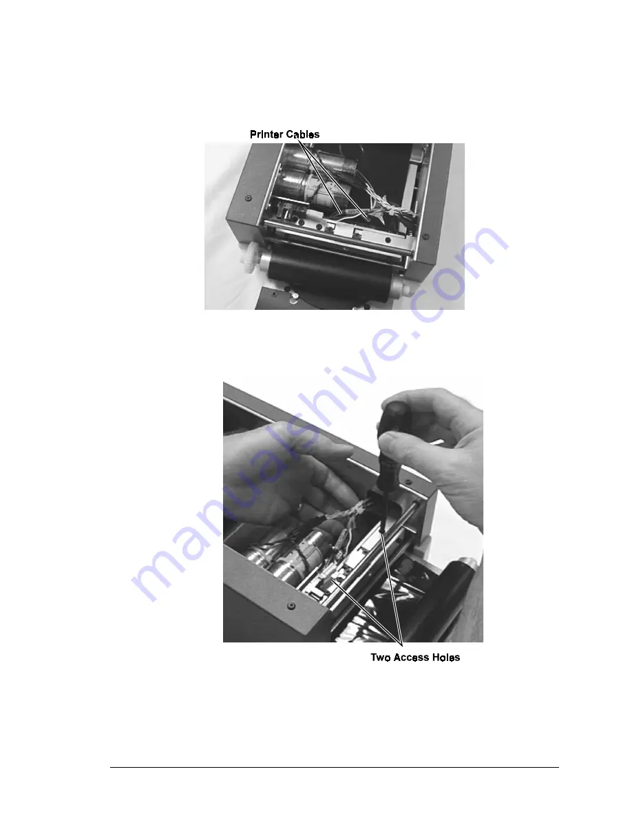
Align the printhead holes to the printhead pivot arm assembly. The screws must
be removed from the recessed holes.

6.


Install one of the Torx screws into the hole and tighten it up while keeping the
printhead aligned with the other hole. The bcakside of the printhead must be flush
with the mounting block. Install the other screw through the other access hole.
See the figure below.

7.


If a piece of paper was placed on the drawer, remove it.

8.


Install the print ribbon.

Содержание Perfect Image

Страница 1: ...Printhead Replacement and Adjustment Guide for the CD Printer 110553 001 Revision B...

Страница 2: ...bles Technical Website http www rimage com technical Rimage Europe Hans B ckler Sta e 7 63128 Dietzenback Germany 06074 8521 0 FAX 06074 8521 21 1999 2000 Rimage Corporation Rimage is the trademark of...

Страница 3: ...printhead replacements Required Tools The following procedure to replace and adjust the CD printer s printhead requires a CPR print head replacement kit 210538 001 This kit includes the necessary scr...

Страница 4: ...under the printhead to protect the printhead 7 Using a T10 Torx Screwdriver remove the four screws located on the sides of the printhead cover See the figure below 8 Slide the printhead cover upward t...

Страница 5: ...the top of the printhead pivot arm assembly see the figure below The printhead is released from the printhead assembly You may need to remove the sesnor from the optical sensor bracket to gain access...

Страница 6: ...the printer slide the new printhead under the printhead pivot arm assembly See the figure below 3 Plug in all of the cables to the printhead before installing the screws Some printheads have three con...

Страница 7: ...he recessed holes 6 Install one of the Torx screws into the hole and tighten it up while keeping the printhead aligned with the other hole The bcakside of the printhead must be flush with the mounting...

Страница 8: ...was open before the diagnostics was selected 4 Place a new lacquer disc on the drawer A lacquer disc has the best print surface and therefore provides the best indication if the printhead is adjusted...

Страница 9: ...gain access to the printhead cover 11 Power the printer off 12 Remove the four T10 screws and then pull the printhead cover upward to remove it Be careful not to damage the screwheads Picture shown o...

Страница 10: ...d then go the other direction by loosening the back brass setscrew first then tighten the front brass setscrew Make small adjustments and test after each adjustment 21 Once the optimum print is acquir...

Отзывы: