background image

Do not change the setting for the out-feed table

again. This will only change if the blades

are replaced or sharpened.

12

Setting Out-feed Table to Cutter-head Knives

WARNING

1. Unplug the Jointer from the power source.

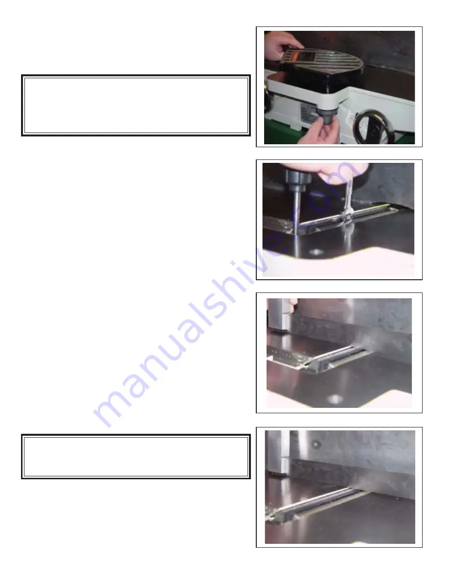
2. Remove the blade guard by turning knob. (Figure

16) clockwise while lift up on the blade guard.
Caution: Blades are sharp! Use care  while
working around the blades.

3. Open the rear door and move the motor belt until

the blade lock hole is lined up (Figure 17).

4. Insert blade lock tool. This locks the head in the

proper position for replacing the first blade.

5. Loosen table lock screw (C, Figure 15) and gib

lock screw (D, Figure 15) and raise the out-feed
table to the height of blade number one by turning
hand wheel.  Counter-clockwise will cause the out-
feed table to rise.  Clockwise will cause the out-
feed table to lower.  Set a straight edge on the out-
feed table (Figure 18). Position of the table and
Straight edge should look like Figure 19.  Use care
when handling the straight edge near the blades
so as not to damage them.

6. When the out-feed table and blade number one

are the same height, tighten gib and table lock
screws

.

7. Bring the straight edge toward the left of the jointer

and confirm that blade number one is at the same
height at the left of the table as it is at the right
side of the table.

DO NOT connect machine to power source

at this time!

Cutter-head blades are extremely sharp!

Use Caution when hands are near the cutter-head!

Failure to comply may cause serious injury!

Figure 18

Figure 19

Figure 17

Figure 16

Содержание 20-110

Страница 1: ...information www rikontools com or info rikontools com For Parts or Questions techsupport rikontools com or 877 884 5167 Record the serial number and date of purchase in your manual for future referenc...

Страница 2: ...LCOHOL ALWAYS WEAR PROPER APPAREL Never wear loose clothing or jewelry that might get caught in moving parts Rubber soled footwear is recommended for the best footing ALWAYS USE SAFETY GLASSES AND WEA...

Страница 3: ...ID ACCIDENTAL STARTING Make sure switch is in OFF position before plugging in cord NEVER LEAVE TOOLS RUNNING UNATTENDED Special Safety Rules For Jointers SAVE THESE INSTRUCTIONS Refer to them often 3...

Страница 4: ...t Safety Warnings 2 Jointer Safety Rules 3 Specifications 4 Contents of Package 5 Unpacking and Setup 5 Loose Parts 6 Getting To Know Your Jointer 7 Assembly 8 Installing Bed to Stand 8 Installing Pol...

Страница 5: ...Unit shipped in two cartons Main Unit Carton 1 Bed Assembly 1 FenceAssembly 1 SwitchAssembly w support 1 Cutter Guard 2 Push Blocks 1 Operator s Manual w Warranty Card 1 Fence Base Casting 2 Hand Whe...

Страница 6: ...ve Place parts on a protected surface 2 Report any shipping damage to your local distributor 3 Clean all rust protected surfaces bed fence etc with kerosene or diesel oil Do not use gasoline paint thi...

Страница 7: ...ustment Handle 5 Cutter Guard 6 In feed Table 7 Hand Wheel for In feed Table 8 On Off Switch 8 9 10 11 12 13 14 9 Out feed Table Lock Knob 10 Fence Tilt Lock Handle 11 Belt Guard 12 Fence Adjustment L...

Страница 8: ...t on the cutter head pulley and through the opening in the cabinet and onto the motor pulley Fig 3 2 If necessary loosen the motor turn buckle to loosen the motor Verify that the Multi V Belt is posit...

Страница 9: ...to the table bed Fig 7 using 13mm socket wrench 2 Align top of the fence base casting flush with the table surface and tighten Installing Fence to Bed 1 Remove the lock handle A Figure 8 flat washer a...

Страница 10: ...1 on the power switch column 7 Adjust the switch B Fig 11 to the desired angle 8 Re tighten the adjustment knob A Fig 11 on the power switch column 90 Fence Adjustment Note Whenever making an adjustme...

Страница 11: ...ut G Figure 14 4 Tighten lock handle B Figure 14 Depth Lock Handle 1 Attach depth lock handle A Figure 15 This should be attached before Depth Limiting Stop B Figure 15 for easier installation Depth L...

Страница 12: ...to the height of blade number one by turning hand wheel Counter clockwise will cause the out feed table to rise Clockwise will cause the out feed table to lower Set a straight edge on the out feed ta...

Страница 13: ...and all three blades are set at the same height in the cutter head If the out feed table is set too high a curved finished surface results If the out feed table is set too low gouging will result at...

Страница 14: ...cover by placing bottom of panel into access in stand and fasten by turning latch knob Figure 22 Figure 22 Figure 23 Installing Dust Chute 1 Attach the dust chute See Figure 23 to the base with four...

Страница 15: ...LL PREVENT UNNECESSARY PROBLEMS Keep the table clean to ensure accurate cutting Keep the outside of the machine clean to ensure accurate operation of all moving parts and prevent excessive wear Keep t...

Страница 16: ...utfeed tables Loose gibs Tighten the gibs Finish stock is concave on the end Knives are set higher than the outfeed table Raise outfeed table level with knives Back side of finish stock is thicker tha...

Страница 17: ...ion Cutterhead Knife Knife Lock Bar Bearing Housing Bearing Housing Cutterhead Pulley Hex Screw Cutterhead Locking Flat Washer 6mm Key Stud Bolt 10mm Lock Washer 10mm Screw Cutterhead Set Ball Bearing...

Страница 18: ...18 Fence Assembly...

Страница 19: ...ex Bolt M8 1 25x25 Plastic Bar Handle Pin Roll Cam Wheel Hex Socket Bolt M8 1 25x25 Hex Socket Bolt M8 1 25x25 Tilt Shaft Worm Gear Hex Bolt M8 1 25x20 Tube Pin Roll Tilt Plate Hex Bolt M6 1 0x12 HexN...

Страница 20: ...20 Stand and Motor Assembly...

Страница 21: ...h Support Upper Lock Knob Switch Support Lower Hex Bolt M8 1 25x12 Flat Washer 8mm Pan Head Screw M5 0 08x16 J Belt 5940 Hex Bolt M6 1 0x12 Flat Washer 6mm Motor Pulley Key Motor Carriage Bolt M8 1 25...

Страница 22: ...22 Bed Assembly...

Страница 23: ...Nut Flat Washer 10mm Bushing Adjusting Screw Ball Crank Pivot Pin Set Screw Lock Screw Hand Wheel Handle Handle Shaft Bolt Front Table Retaining Washer Spring Spring Knob Retainer Pointer Ball Crank B...

Страница 24: ...24 NOTES...

Страница 25: ...commercial industrial or educational purposes This limited warranty does not apply to accessory items such as blades drill bits sanding discs or belts and other related items Seller shall in no event...

Страница 26: ...For more information 400 West Cummings Park Suite 1000 Woburn MA 01801 877 884 5167 781 933 8400 techsupport rikontools com www rikontools com Copyright Richen Enterprise Inc 2005 Printed in China...

Отзывы: