Riken Keiki GD-F4A-A Скачать руководство пользователя страница 5


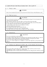
2.IMPORTANT INSTRUCTIONS FOR THE SAFETY


2-1.Danger cases 

 
2-2.Warning cases 


2-3.Precaution 


2-4.Caution for explosion proof (In case of intrinsically safe design)   


In case of non-explosion poof system, do not use this unit at the place where combustible gas may exist. 


・Do not cut the wire for protective ground both inside and outside of instrument. Or, do not disconnect the 

connection of the ground terminals. 

・Before starting the operation, check if any defect is not found on the protective grounding. 
・If there is any defect on the protective functions such as protective grounding, do not start the operation. 
・It is very dangerous if the instrument gives oxygen deficiency alarm. 

Take appropriate measures based on your judgment at that time. 

・Perform gas calibration at proper interval. 
・Do not change or remodel the circuit/structure of this unit. 
・Do not disassemble the sensor since there is a electrolyte inside. 
  If your finger touches the electrolyte, wash your finger way with water immediately. 

WARNING 


・Do not use a walky-talky around the instrument. 

The indication might be affected by the electromagnetic wave generated by the walky-talky if it is used near 
the instrument.    When the walky-talky is used, be away enough from the instrument not to affect. 

・Do not control other equipment by using outputs of this detector. 
  This  is  not  a  control  equipment.  It  is  prohibited  to  control  other  equipment  by  using  outputs  of  this 

detector. 

CAUTION 


・Do not use this detector head expect for the measurement of oxygen content in a mixture of air and 

combustible gas or vapors, or a mixture of air and toxic gases. 

・When cleaning this unit, do not use dry cloth but use the wet cloth not to change the static electricity on plastic 

part.   

DANGER 

DANGER 

Содержание GD-F4A-A

Страница 1: ...PT2E 2501 Oxygen Gas Detector Head GD F4A A Operating Manual PT2 151...

Страница 2: ...addition it may be fluctuated by environmental temperature humidity etc changes in the installation site 2 The alarm must be set within a range where the performance of the detector can be ensured Th...

Страница 3: ...iping connection 11 OPERATION METHOD Preparation for start up 12 Start up 12 Stopping the operation 12 MAINTENANCE AND INSPECTION Inspection frequency and items 13 How to calibration Required kit and...

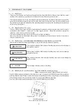
Страница 4: ...trinsically safe system in combination with zener barrier option to be able to install in hazardous area Definition of DANGER WARNING CAUTION and NOTE This manual contains the following headings to en...

Страница 5: ...terval Do not change or remodel the circuit structure of this unit Do not disassemble the sensor since there is a electrolyte inside If your finger touches the electrolyte wash your finger way with wa...

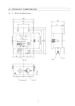
Страница 6: ...4 PRODUCT COMPONENTS External dimensions Cable inlet Cable inlet Sensor Gas inlet Protective ground Gas outlet For U bolt Cable inlet Sensor Gas inlet Protective ground Gas outlet For U bolt...

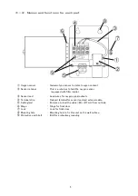
Страница 7: ...d with filter inside Sensor lead Lead wires for oxygen signal outputs Terminal strip Relayed terminal for sensor lead and external cable Cable gland Entrance to lead the cable 8 11mm from outside Hing...

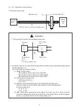
Страница 8: ...ivision ia Group C 3 Relations between allowable inductance Lo and allowable capacitance Co of intrinsic safety circuit and external wiring inductance Lw and capacitance Cw of intrinsic safety circuit...

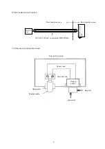
Страница 9: ...inside detector head Drip proof housing Sensor lead Terminal strip Cable gland Shielded cable Oxygen sensor Gas inlet Gas outlet Detector head Indicator alarm unit Non hazardous area Non hazardous ar...

Страница 10: ...aces where the temperature is drastically changed Places exceeding operating temperature and humidity Maintenance space A certain maintenance space must be secured around the detector head so that the...

Страница 11: ...he optional zener barrier between this unit and indicator alarm unit at non hazardous area See below fig Connect the other end cable to the indicator alarm unit Connect the shield s drain wire at the...

Страница 12: ...ent to the detector response time Be sure to attach the gas suction port at the end of gas detection point Be sure to put dust filter in front of gas detector If sampled gas contains water and corrosi...

Страница 13: ...ble and make it to 26hPa at a maximum As the load to oxygen sensor is high on this method aspirator suction method shall be used only when the pump cannot be used If the sample gas pressure would fluc...

Страница 14: ...to 1 0L 0 3mL min Be sure to perform gas calibration at the time of new installation Correct reading may not be obtained before gas calibration Stopping the operation Stop the sample gas supply to thi...

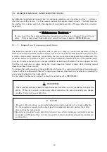
Страница 15: ...cessary to carry out gas calibration at least every 6 months The law in Japan sets forth that the unit must issue an alarm during the circuit inspection related to alarm while providing normal operati...

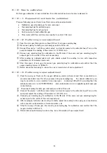
Страница 16: ...g bag for calibration and confirm that the oxygen reading returns to 20 9vol Return disconnected piping to where they were completion of zero adjustment Performing a span adjustment Pack the span gas...

Страница 17: ...at the top of terminal strip and disconnect two lead black and white wires Loosen the screw for sensor stopper and take off the sensor stopper Pull out the sensor upward from the holder Insert new sen...

Страница 18: ...rval Q ty unit 1 O ring sensor side in the holder 1 year 3 6 years 1 2 O ring Housing side in the holder 1 year 3 6 years 1 NOTE The replacement interval will change depending on operating condition a...

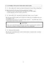
Страница 19: ...tor head is relocated select a new place in accordance with 4 2 Installation place and 4 4 Installation works For information on wiring work see 4 5 Caution at wiring construction The unpowered time m...

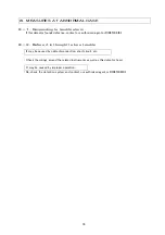
Страница 20: ...agent or RIKEN KEIKI Before it is thought to be a trouble Check the wirings around the related instruments as well as this detector head It may be caused by improper operation Re check the detection...

Страница 21: ...8 11mm Piping port Rc1 8 with half union for O D 8 1 Operating temperature 10 40 non rapidly vary It may differ according to mounted sensor Operating humidity Less than 95 RH non condensing It may dif...

Страница 22: ...er is opened and covered with a barrier The negative electrode is installed in contact with the barrier Lead wires are drawn from the positive and negative electrodes to obtain outputs A thermistor is...

Страница 23: ...Safety retainer for explosion protection by limiting the energy of electric current within a non ignition level CVVS This is a kind of connecting cable between indicator alarm unit and oxygen detecto...

Страница 24: ...Manual Log Rev Amendment Issue data 0 First issue 2017 2 17 1 Addition Declaration of Conformity 2022 7 22...

Страница 25: ......

Страница 26: ...1...

Отзывы: