15
20017376
GB
Operation
Before carrying out the conversion:
Switch off the electricity supply.
close the fuel interception tap.
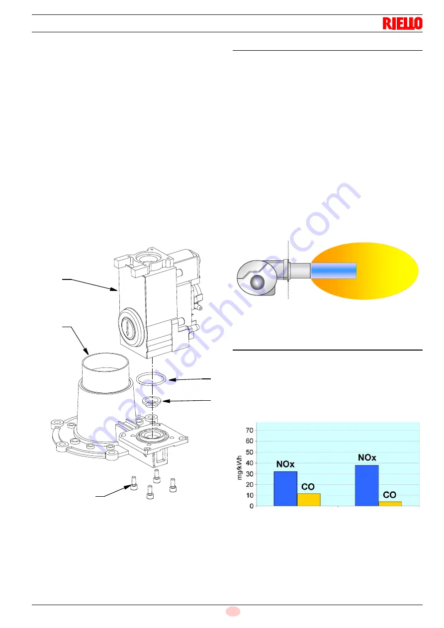
Disassemble the gas valve 1) (Fig. 12) from the venturi unit
2), removing the screws 3).
Substitute the diaphragm 4) on the gas valve 1) with the one
supplied.
House the diaphragm 4) in the gasket 5).
The table alongside shows the various diameters of the dia-
phragms calibrated on the basis of the type of gas used.
Reassemble the gas valve and carry out all the adjustment
operations described above.
The correct values for the gas G31 (LPG) are:
CO
2
10 - 10,7% or O
2
5,7 - 6,2%.
To correct these values act on thee gas valve in the following
way:
–
To increase the gas delivery and the CO
2
: turn the screw V1
in anticlockwise direction (unscrew)
–
To reduce the gas delivery and the CO
2
: turn the screw V1 in
a clockwise direction (screw up)
the necessary values of the pressure on the gas mains are:
–
for G20 = 20 mbar
–
for G31 = 37 mbar
6.7
Combustion head
The combustion head comprises a highly heat resistant cylinder
whose surface features numerous holes, encased in a metal
"mesh" (Fig. 13).
The air-gas mixture is pushed inside the cylinder and out of the
head through the holes in the perimeter. Combustion starts when
the air-gas mixture is ignited by a spark generated by the elec-
trode.
The metal "mesh" is the combustion head's most essential ele-
ment since it improves burner performance considerably.
The flame developed on the surface of the head is perfectly re-
tained and adheres to the mesh when operating at the maximum
setting. This allows modulating ratios as high as 6:1, avoiding the
danger of flashback when modulating is at its minimum.
The flame features an extremely compact geometry, meaning
that there is no risk of contact between the flame and parts of the
boiler, consequently eliminating the possible problem of poor
combustion.
The flame's structure means that smaller combustion chambers
can be developed, designed to exploit this particular feature.
6.8
Emissions
The burners' emission values prove much lower than the limits
laid down by the strictest standards. The flame's distribution and
its spread over a large surface means that the burner manages
to limit the formation of thermal NOx, the main causes of pollutant
emission.
Fig. 12
D9712
1
2
3
5
4
Fig. 13
D9714
Fig. 14
Class limit 3 = 80 mg/kWh
D9715
Modulation
minimum 25 kW
Modulation
maximum 125 kW


