background image

24

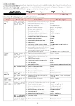
REGOLAZIONE BRUCIATORE

Per ottenere una regolazione ottimale del bru-
ciatore è necessario effettuare l’analisi dei gas
di scarico della combustione all’uscita della cal-
daia.

Regolare in successione:
1 - Potenza Max
2 - Potenza Min
3 - Verifica modulazione
4 - Potenza all’ accensione
5 - Potenze intermedie
6 - Pressostato aria
7 - Pressostato gas di minima
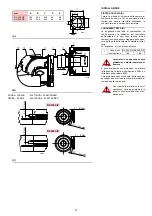
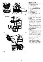
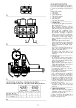
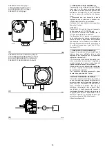
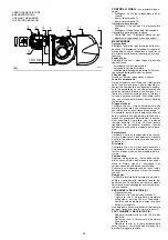
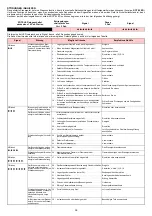
1 - POTENZA MAX

- La potenza MAX va scelta entro il campo di

lavoro riportato a pag. 10.

- Nella descrizione precedente abbiamo

lasciato il bruciatore acceso, funzionante alla
potenza MIN. Premere ora il pulsante 2)(A) e
tenerlo premuto fino a raggiungere la mas-
sima apertura delle serrande aria. Durante
tale operazione controllare la stabilità di
fiamma e il valore della CO

2

: se risulta insta-

bile aumentare o diminuire la taratura della
vite di taratura V presente sulla valvola in
modo da raggiungere il corretto valore di 

CO

2

(8.2-9%)

.

- Misurare la portata del gas al contatore.

A titolo orientativo può essere ricavata dalle
tabelle di pag.12, basta leggere la pressione
del gas sul manometro a U o digitale, vedi fig.
(C) pag. 22.

- Per modificare la potenza Max agire sul pul-

sante (-) fino al valore desiderato e correg-
gere la posizione della Camma I. 

- Riverificare il valore corretto della CO

2

 ed

eventualmente correggerlo con la vite V della
valvola gas.

2 - POTENZA MIN

- Ad accensione avvenuta portare gradual-

mente il servomotore verso la posizione di
minima fiamma (regolazione fatta in fabbrica)
premendo il pulsante 2)(A).

- Eseguire l’analisi del gas di scarico e agire su

N della valvola in modo da ottenere il valore
corretto di 

CO

2

 (7.8 - 8.5%)

.

- Misurare la portata del gas al contatore.
- La potenza Min va scelta entro il campo di

lavoro riportato a pag.10.

- Se la potenza di prima fiamma deve essere

modificata agire sulla camma V.

- Nota: il servomotore segue la regolazione

della camma V solo quando si riduce l’angolo
della camma. Se bisogna aumentare l’angolo
della camma, è necessario prima aumentare
l’angolo del servomotore con il tasto (+), poi
aumentare l’angolo della camma V ed infine
riportare il servomotore nella posizione di
potenza MIN con il tasto (-).

- Riverificare il valore corretto della CO

2

 ed

eventualmente correggerlo con la vite N della
valvola gas.

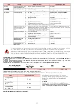
3 - VERIFICA MODULAZIONE

- Portare il servomotore alla massima potenza

controllando il valore corretto della CO

2

 e se

necessario correggere la vite V.

- Portare il servomotore alla minima potenza
controllando il valore corretto della CO

2

 e se

necessario correggere la vite N.
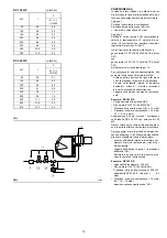
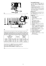
N

V

(A)

1

2

D791

(C)

(B)

D3518

D8728

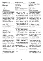
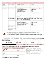
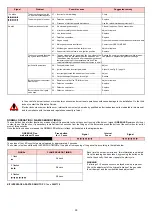
VALORI OTTIMALI DI TARATURA - OPTIMALE EINSTELLWERTE

OPTIMUM CALIBRATION VALUES - VALEURS POUR UN REGLAGE PARFAIT

Potenza MIN

Mindestleistung

MIN output

Puissance MIN

Potenza MAX

Höchstleistung

MAX output

Puissance MAX

CO

2

  (%)

O

2

  (%)

CO

2

  (%)

O

2

  (%)

METANO - METHAN
METHANE - METHANE

8

6.6

8.5

5.7

GPL - Flüssiggas - LPG

9.5

6.4

10

5.6

(D)

Содержание RX 350 S/P

Страница 1: ...uciatori di gas premiscelato Gas Vormisch Brenner Premixed gas burners Br leurs de gaz pr m lang Funzionamento bistadio progressivo Zweistufig gleitender Betrieb Progressive two stage operation Foncti...

Страница 2: ......

Страница 3: ...esente che la serie di apparecchi di seguito specificata conforme al modello del tipo descritto nella dichiarazione di confor mit CE ed prodotta e messa in circolazione in conformit alle richieste def...

Страница 4: ...d bescheinigt dass die nachfolgend aufgef hrte Ger teserie dem in der CE Konformit tserkl rung beschriebenen Modelltyp entspri cht sowie gem den im Gesetzeserlass vom 8 Januar 2004 und 17 Juli 2009 fe...

Страница 5: ...certified that the apparatuses specified below conform with the model of the type described n the CE conformity declaration and they are produced and placed in circulation in conformity with the prov...

Страница 6: ...que la s rie d appareils sp cifi e ci apr s est conforme au mod le du type d crit dans la d claration de conformit CE et elle est produite et mise en circulation conform ment aux demandes d finies dan...

Страница 7: ...1 A Particolare 1 della figura A nella stessa pagina del testo 1 A p 8 Particolare 1 della figura A riportata a pagina 8 INHALT TECHNISCHE ANGABEN Seite 4 Zubeh rteile 4 Brennerbeschreibung 9 Verpack...

Страница 8: ...e as text 1 A p 8 Part 1 of figure A page number 8 INDEX DONN ES TECHNIQUES page 6 Accesoires 6 Description br leur 9 Emballage Poids 9 Encombrement 9 Equipement standard 9 Plages de puissance 11 Chau...

Страница 9: ...ACE ADAPTER RMG TO PC Codice 3002719 RAMPE GAS SECONDO NORMA EN 676 complete di valvole regolatore di pressione e filtro vedere a pagina 18 KIT CONTROLLO TENUTA PER VALVOLA SIEMENS Codice 20064286 per...

Страница 10: ...Code 3002719 GASARMATUREN GEM NORM EN 676 mit Ventilen Druckregler und Filter siehe Seite 18 KIT DICHTHEITSKONTROLLE F R VENTIL SIEMENS Code 20064286 f r RX 500 S P MODELL RX 350 S P RX 500 S P TYP 8...

Страница 11: ...er KIT INTERFACE ADAPTER RMG TO PC Code 3002719 GAS TRAIN ACCORDING TO REGULATION EN 676 with valves pressure governor and filter see page 18 SIEMENS CONTROL VALVE LEAK DETECTION DEVICE KIT Code 20064...

Страница 12: ...e installer sur le g n rateur de chaleur KIT INTERFACE ADAPTER RMG TO PC Code 3002719 RAMPES GAZ SELON LA NORME EN 676 avec vannes regulateur de pression et filtre voir p 18 KIT CONTR LE D TAINCHEIT P...

Страница 13: ...7 PAESE LAND COUNTRY PAYS CATEGORIA KATEGORIE CATEGORY CATEGORIE IT AT GR DK FI SE II2H3B P ES GB IE PT II2H3P NL II2L3B P FR II2Er3P DE II2ELL3B P BE I2E R B I3P LU PL II2E3B P...

Страница 14: ...F 40 Vi sono due possibilit di blocco del bruciatore BLOCCO APPARECCHIATURA l accensione del pulsante dell apparecchiatura 17 A avverte che il bruciatore in blocco Per sbloccare premere il pulsante BL...

Страница 15: ...board for RWF 40 Two types of burner failure may occur CONTROL BOX LOCK OUT if the control box 17 A pushbutton lights up it indicates that the burner is in lock out To reset press the pushbutton MOTO...

Страница 16: ...ato alla tem peratura ambiente di 20 C e alla pressione barometrica di 1013 mbar circa 0 m s l m CALDAIA DI PROVA I campi di lavoro sono stati ricavati in speciali caldaie di prova secondo la norma EN...

Страница 17: ...a values have been obtained considering an ambient temperature of 20 C and an atmospheric pressure of 1013 mbar approx 0 m above sea level TEST BOILER The firing rates were set in relation to special...

Страница 18: ...naturale G 20 PCI 9 45 kWh Sm3 Pressione del gas alla presa 1 B 10 mbar Pressione in camera combustione 1 6 mbar 10 1 6 8 4 mbar Alla pressione 8 4 mbar colonna 1 corrisponde nella tabella RX 350 S P...

Страница 19: ...Example RX 350 S P Maximum output operation Natural gas G 20 PCI 9 45 kWh Sm3 Gas pressure at test point 1 B 10 mbar Pressure in combustion chamber 1 6 mbar 10 1 6 8 4 mbar A maximum output of 300 kW...

Страница 20: ...re utilizzati su caldaie inversione di fiamma E possibile inserire una protezione in materiale refrattario tra la testa di combustione 6 B e il refrattario della caldaia 8 B Tale protezione deve conse...

Страница 21: ...of the boiler door complete with its fettling The range of lengths available L mm is as follows The burners cannot be used on flame inversion boilers It is possible to insert a protection made of ref...

Страница 22: ...o 3 B e la guarnizione in gomma siliconica 4 B Togliere la vite 2 B p 14 dalle guide 3 B p 14 Togliere la vite 1 B p 14 e scollegare i cavi della sonda e dell elettrodo quindi arretrare il bruciatore...

Страница 23: ...screw the studs 2 B onto the boiler plate 1 B position the refractory gasket 3 B and the silicone rubber gasket 4 B remove the screw 2 B p 14 from the slide bars 3 B p 14 remove the screw 1 B p 14 and...

Страница 24: ...atori con potenza massima superiore a 1200 kW 13 Adattatore rampa bruciatore PF Presa di pressione camera di combustione PL Presa di pressione aria P1 Pressione alla testa di combustione P2 Pressione...

Страница 25: ...tton cock 5 Filter 6 Minimum gas pressure switch 7 Safety solenoid 8 Operating solenoid valve 9 Pressure governor 10 Standard issue burner gasket with flange 11 Burner 12 Gas valve 7 8 leak detection...

Страница 26: ...llegare la presa caldaia A con la presa di pressione camera di combustione PF e la presa B presente sul ventilatore con la presa di pressione aria PL mediante i tubi precedentemente tagliati ATTENZION...

Страница 27: ...on chamber Cut the 6mm diameter plastic tube supplied with the burner into two Connect boiler pressure test fitting A with air pressure test line PF and pressure test fitting B to be found on the fan...

Страница 28: ...a V Camma V 20 Minima potenza AVVIAMENTO BRUCIATORE Chiudere i telecomandi e mettere l interruttore 1 F in posizione MAN Appena il bruciatore RX 500 S P si avvia con trollare il senso di rotazione del...

Страница 29: ...not alter the factory setting for the 4 cams simply check that they are set as indicated below Cam I 90 Limits rotation toward maximum position Cam I I 0 Limits rotation toward the minimum position Wh...

Страница 30: ...N Ad accensione avvenuta portare gradual mente il servomotore verso la posizione di minima fiamma regolazione fatta in fabbrica premendo il pulsante 2 A Eseguire l analisi del gas di scarico e agire s...

Страница 31: ...aleur d sir e et corriger la position de la came I V rifier de nouveau si la valeur de CO2 est correcte et la corriger ventuellement avec la vis V de la vanne gaz 2 PUISSANCE MINIMUM Quand l allumage...

Страница 32: ...to Esempio potenza MAX di funzionamento 600 kW La potenza all accensione deve essere uguale o inferiore a 300 kW con ts 2 s 200 kW con ts 3 s Per misurare la potenza all accensione scollegare la spina...

Страница 33: ...o or lower than 300 kW with ts 2 s 200 kW with ts 3 s In order to measure the firing output disconnect the plug socket 21 A p 8 on the ionization probe cable the burner will fire and then go into lock...

Страница 34: ...bruciatore con il pressostato regolato a inizio scala C Con il bruciatore funzionante alla potenza mas sima aumentare la pressione di regolazione girando lentamente in senso orario l apposita manopoli...

Страница 35: ...le r glage du pressostat gaz seuil minimum apr s avoir effectu tous les autres r glages du br leur avec le pressostat r gl en d but d chelle C Lorsque le br leur fonctionne la puissance MAX augmenter...

Страница 36: ...a e la corretta posizione del pressostato aria Se la temperatura o la pressione bassa per cui il telecomando TR chiuso il bruciatore aumenta progressivamente la potenza fino al valore MAX tratto B C S...

Страница 37: ...at the flame is present and that the air pres sure switch is in the correct position If the temperature or pressure is low and the TR load control is consequently closed the burner progressively incre...

Страница 38: ...la sonda non presentino accentuate deformazioni e ossida zioni superficiali Controllare che le distanze indicate nella fig C pag 14 siano ancora rispettate Se necessario eliminare l ossido superficia...

Страница 39: ...e neither the electrodes nor probe feature marked warping or oxidation on surfaces Make sure distances are still in line with those indicated in fig C page 14 Where necessary remove oxide from the sur...

Страница 40: ...lla camera di combustione Toglierlo 16 Verificare l assenza di condensa all interno della prote zione collegamenti del gruppo elettrodi Controllare le guarnizioni e il serraggio delle viti 3 lampeggi...

Страница 41: ...regolato il pressostato gas di minima Il calo di pressione repentino che segue l apertura della valvola provoca l apertura temporanea del pressostato stesso subito la valvola chiude e si ferma Ridurr...

Страница 42: ...Pr fen Sie das Nichtvorhandensein von Kondensation im Inneren des Schutzes der Anschl sse der Elektro dengruppe Pr fen Sie die Dichtungen und die Festigkeit der Schrauben 3 Blinken Brenner geht nicht...

Страница 43: ...er eingestellten Wert sehr nahe Der pl tzli che Druckabfall beim ffnen des Ventils bewirkt die ffnung des Druckw chters Dadurch schlie t sich das Ventil sofort wieder und der Brenner stellt sich ab De...

Страница 44: ...the combustion chamber Remove it 16 Check there is no condensation inside the protection on the electrode unit connections Check the gaskets are undamaged and the screws are well tightened 3 x blinks...

Страница 45: ...ose to the value to which the gas pressure switch has been set The sudden drop in pressure after valve opening causes temporary opening of the pressure switch itself the valve immediately closes and t...

Страница 46: ...l absence de condensation l int rieur de la pro tection des branchements du groupe d lectrodes Contr ler les joints et le serrage des vis 3 clignotements Le br leur ne d marre pas et met en s curit 1...

Страница 47: ...la valeur a laquelle le pressostat gaz minimum est r gl La chute de pression soudaine suite l ouverture de la vanne pro voque l ouverture temporaire du pressostat la vanne se ferme aussit t et le br...

Страница 48: ...szuf ren Electrical connections set by installer Raccordements lectriques par l installateur Collegamenti elettrici a cura dell installatore Elektroanschlusse vom Installateur auszuf ren Electrical co...

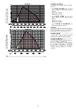
Страница 49: ...43 0 1 2 3 3 3 4 3 5 3 3 3 3 3 3 3 3 3 3 4 3 RX 350 S P...

Страница 50: ...44 0 1 1 1 2 1 3 1 1 1 1 1 1 1 1 1 1 2 1 445 RX 500 S P...

Страница 51: ...45 0 1 20 3 4 5 6 2 6 2 7 6 7 8 6 0 0 9 6 7 6 7 7 6 0 6 0 0 0 0 6 26 2 6 6 2 6 0 6 0 7 8 0 6 7 RX 350 S P...

Страница 52: ...46 0 1 2 2 3 2 4 2 4 5 4 5 6 1 6 1 7 6 7 8 6 9 6 7 6 7 7 6 6 6 16 1 6 6 1 6 6 7 8 6 7 RX 500 S P...

Страница 53: ...47 0 0 0 1 0 2 0 0 0 0 0 0 0 0 0 0 1 0 RX 350 S P...

Страница 54: ...48 0 0 0 1 0 2 0 0 0 0 0 0 0 0 0 0 1 0 RX 500 S P...

Страница 55: ...49 0 0 1 2 3 45 6 6 67 8 8 0 8 8 9 8 6 6 6 6 6 6 6...

Страница 56: ...1 87 87 59 8 7 867 1 3 1 1 11 4 B 1 2 C 1 C D 8 8 8 7 8 5 5 1 93 3 B A12 A1 A 1 6 91 1D 1 3 1 7 1 81 61D 6 6D 51 5 675 B 7 8 1 B E 11 7 2 87 87D 9 F 9 9 9 9 F 7 7 8 F 68 G 97 6 67 F 5 6 7 6 7 5 F 5 9...

Страница 57: ...Presa 5 poli XP6 Presa 6 poli XP7 Presa 7 poli X4 Spina 4 poli X5 Spina 5 poli X6 Spina 6 poli X7 Spina 7 poli LEGENDE DER SCHALTPL NE A Steuerger t RMG B Entst rungsfilter BT Temperaturf hler BP Druc...

Страница 58: ...5 pin plug X6 6 pin plug X7 7 pin plug L GENDE SCH MAS LECTRIQUES A Bo te de contr le RMG B Filtre contre les parasites BT Sonde de temp rature BP Sonde de pression C Condensateur F1 Relais thermique...

Страница 59: ...motore per un forte aumento dell assorbimento dovuto alla mancanza di una fase Se il motore alimentato a stella 400V il cur sore va posizionato sul MIN Se alimentato a triangolo 230V il cursore va pos...

Страница 60: ...e le moteur br le cause d une forte augmentation de l absorption due l absence d une phase Si le moteur est aliment en toile 400V le curseur doit tre plac sur MIN S il est aliment en triangle 230V le...

Страница 61: ......

Страница 62: ......

Страница 63: ......

Страница 64: ...Con riserva di modifiche nderungen vorbehalten Subject to modifications Sous r serve de modifications RIELLO S p A I 37045 Legnago VR Tel 39 0442 630111 http www riello it http www rielloburners com...

Отзывы: