20040563
24
GB
Installation
5.9.3
Gas pressure
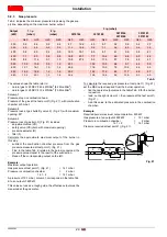
Tab. K indicates the minimum pressure drops along the gas sup-
ply line, depending on the maximum burner output.
Tab. K
The values shown the table refer to:
–
natural gas G 20 NCV 9.45 kWh/Sm
3
(8.2 Mcal/Sm
3
)
–
natural gas G 25 NCV 8.13 kWh/Sm
3
(7.0 Mcal/Sm
3
)
Column 1
Pressure drop on combustion head.
Pressure of the gas at the test point 1)(Fig. 21), with combustion
chamber at 0 mbar;
Column 2
Pressure loss at gas butterfly valve 2) (Fig. 21) with maximum
opening: 90°.
Column 3
Pressure loss of gas train 3) (Fig. 21) includes:
•
adjustment valve (VR)
•
safety valve (VS) (both with maximum opening)
•
pressure adjuster (R)
•
filter (F)
Calculate the approximate maximum output of the burner in
this way:
–
subtract the combustion chamber pressure from the gas
pressure measured at test point 1) (Fig. 21).
–
Find, in the table Tab. K related to the burner concerned, the
pressure value closest to the result of the subtraction.
–
Read off the corresponding output on the left.
Example:
Maximum output operation
Gas pressure at test point 1) (Fig. 21)
=
14.1 mbar
Pressure in combustion chamber
=
2 mbar
14.1 - 2
=
12.1 mbar
A pressure of 12.1 mbar, column 1, corresponds in the table Tab.
K to an output of 600 kW.
This value serves as a rough guide; the effective output must be
measured at the gas meter.
To calculate the required gas pressure at test point 1) (Fig. 21),
set the MAX output required from the burner operation:
–
find the nearest output value in the table Tab. K for the burner
in question.
–
read, on the right (column 1), the pressure at the test point 1)
(Fig. 21).
–
Add this value to the estimated pressure in the combustion
chamber.
Example:
Required burner maximum output operation: 600 kW
Gas pressure at an output of 600 kW
= 12.1 mbar
Pressure in combustion chamber
=
2 mbar
12.1 + 2
= 14.1 mbar
Pressure required at test point 1) (Fig. 21).
Output
(kW)
1
p
(mbar)
2
p
(mbar)
3
p (mbar)
3970144
3970180
3970146
3970160
3970181
3970182
G20
G25
G20
G25
G20
G25
G20
G25
G20
G25
G20
G25
300
3.2
4.6
0.3
0.4
8.7
12.2
4.3
5.7
3.2
3.6
3.4
3.7
350
4.5
6.3
0.3
0.5
11.2
15.6
5.4
7.1
3.4
4.5
3.6
3.9
400
5.8
8.0
0.4
0.6
14.0
19.1
6.5
8.7
4.1
5.5
3.8
4.1
450
7.1
9.7
0.6
0.8
16.8
23.1
7.7
10.2
4.9
6.6
4.0
4.4
500
8.4
11.4
0.7
1.0
19.8
27.4
9.0
11.9
5.7
7.8
4.2
4.7
550
10.2
13.6
0.9
1.2
23.1
10.2
13.5
6.6
9.1
4.4
5.0
600
12.1
16.1
1.0
1.4
26.6
11.6
15.3
7.6
10.3
4.6
5.3
650
14.0
18.6
1.2
1.6
30.2
12.9
17.2
8.6
11.7
4.9
5.7
680
15.2
20.1
1.3
1.8
32.4
13.8
18.4
9.2
12.5
5.0
6.0
Fig. 21
2
VS
VR
R
3
1
F
D3790
Содержание RS 55/E BLU
Страница 2: ...Translation of the original instructions Traducci n de las instrucciones originales...
Страница 40: ......
Страница 78: ...20040563 38 Appendix Ap ndice...
Страница 79: ...39 20040563 Appendix Ap ndice...
Страница 80: ...20040563 40 Appendix Ap ndice...
Страница 81: ...41 20040563 Appendix Ap ndice...
Страница 82: ...20040563 42 Appendix Ap ndice...


