background image

24

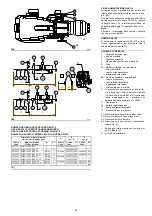
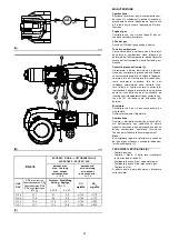
PRESSIONE GAS

Importante

La pressione alla testa del bruciatore da tabella
(A) è riferita a zero in camera di combustione;
per la pressione reale, misurata con un mano-
metro ad U (vedi fig. A pag. 26), aggiungere la
contropressione di caldaia.

Nota

Per la regolazione della rampa gas vedere le
istruzioni che l'accompagnano.

kW

Pressure P1

mbar

Gas 

but 

Adaptor

mbar

Gas train

8 - 10

mbar

MBC-1200

(Rp 2”)

MBC-1900

(DN 65)

MBC-3100

(DN 80)

MBC-5000

(DN 100)

G 20 G 25 G 20 G 25 G 20 G 25 G 20 G 25 G 20 G 25 G 20 G 25

RS 30

0/

E BL

U

1350

7.8

11.6

1.3

2.0

12.2

17.4

6.9

9.1

4.7

5.6

3.7

4.0

1500

9.4

13.9

2.0

2.9

17.0

23.7

8.9

11.8

5.5

6.6

4.0

4.4

2000

12.4

18.5

3.5

5.2

27.5

38.7

13.5

18.7

7.3

9.4

4.6

5.2

2500

13.7

20.4

5.4

8.1

40.2

59.7

19.3

26.4

9.7

12.8

5.3

6.5

3000

15.0

22.4

7.8

11.6

57.8

87.3

25.7

35.0

12.5

16.8

6.4

8.3

3500

20.5

30.6

10.6

15.9

79.4 119.9 32.6

44.4

15.7

21.1

7.8

10.1

3800

23.3

32.7

12.2

18.2

93.8 140.6 37.0

50.4

17.7

23.9

8.7

11.3

RS

 400

/E

 BLU

1800

6.3

9.3

2.9

4.3

23.1

32.5

11.5

15.8

6.5

8.2

4.3

4.9

2000

7.9

11.7

3.5

5.3

27.5

38.7

13.5

18.7

7.3

9.4

4.6

5.2

2500

11.9

17.7

5.5

8.2

40.2

59.7

19.3

26.4

9.7

12.8

5.3

6.5

3000

15.9

23.7

8.0

11.9

57.8

87.3

25.7

35.0

12.5

16.8

6.4

8.3

3500

19.7

29.4

10.8

16.2

79.4

-

32.6

44.4

15.7

21.1

7.8

10.1

4000

22.4

33.5

14.2

21.1 104.6

-

40.1

54.4

19.1

25.8

9.3

12.3

4500

32.5

48.4

17.9

26.7 132.6

-

48.1

66.0

22.8

31.6

10.8

14.8

4590

34.3

40.2

18.6

27.2 137.7

-

49.5

68.2

23.5

32.8

11.1

15.3

RS

 500

/E

 BLU

2500

11.5

17.2

0.6

0.8

40.2

59.7

19.3 26.4

9.7

12.8

5.3

6.5

3000

15.5 23.2

0.8

1.2

57.8

87.3

25.7 35.0 12.5 16.8

6.4

8.3

3500

19.5 29.1

1.1

1.6

79.4 119.9 32.6 44.4 15.7 21.1

7.8

10.1

4000

24.5 36.6

1.4

2.1

104.6 154.6 40.1 54.4 19.1 25.8

9.3

12.3

4500

29.5 44.0

1.8

2.7

132.6

-

48.1 66.0 22.8 31.6 10.8 14.8

5000

35.5 53.0

2.2

3.3

161.2

-

56.3 78.7 26.7 38.1 12.7 17.5

5170

37.6 56.1

2.4

3.5

172.1

-

59.4 83.1 28.2 40.4 13.4 18.5

RS 80

0/E

 BL

U

3500

8.8

13.1

0.4

0.7

79.4 119.9

32.6 44.4 15.7 21.1

7.8

10.1

4000

12.2 18.1

0.6

0.9

104.6 154.6 40.1 54.4 19.1 25.8

9.3

12.3

5000

18.9 28.0

0.9

1.4

161.2

-

56.3 78.7 26.7 38.1 12.7 17.5

6000

25.7 38.1

1.3

2.0

-

-

76.4 105.5 37.0 51.8 17.0 23.2

7000

35.1 53.1

1.8

2.7

-

-

98.1 136.7 48.1 69.2 21.7 30.7

8000

44.6 78.7

2.3

3.5

-

-

122.0 170.8 60.8 88.4 27.1 39.6

8100

45.5 81.2

2.4

3.6

-

-

124.7 174.3 62.3 90.4 27.7 40.5

(A)

Содержание RS 300/E BLU

Страница 1: ...ner Gas burners Brûleurs gaz Funzionamento modulante Modulierender Betrieb Modulating operation Fonctionnement modulant 2916398 0 09 2007 CODICE CODE MODELLO MODELL MODEL MODELE TIPO TYP TYPE TYPE 3898320 3898330 RS 300 E BLU 849 T1 3898422 3898432 RS 400 E BLU 850 T1 3899120 3899130 RS 500 E BLU 856 T1 3911020 3911030 RS 800 E BLU 887 T1 I D GB F Preliminary 20 09 2007 ...

Страница 2: ......

Страница 3: ...tem für die Luft Brennstoffregelung und die Leistungsmodulation 37 Anhang Schaltplan 38 D CONTENTS Technical data page 8 Accessories 8 List of available models 9 Burner description 13 Description of panel board 13 Packaging Weight 15 Standard equipment 15 Max dimensions 15 Firing rates 17 Boilers 17 Test boiler 17 Installation 19 Boiler plate 19 Blast tube length 19 Securing the burner to the boil...

Страница 4: ...0 minima kW 500 950 1000 1200 COMBUSTIBILE GAS NATURALE G20 metano G21 G22 G23 G25 Pressione gas alla potenza max 2 Gas G20 G25 mbar 23 3 32 7 34 3 40 2 37 6 56 1 45 5 81 2 FUNZIONAMENTO Continuo Intermittente min 1 arresto in 24 ore IMPIEGO STANDARD Caldaie ad acqua a vapore ad olio diatermico TEMPERATURA AMBIENTE C 0 40 TEMPERATURA ARIA COMBURENTE C max 60 ALIMENTAZIONE ELETTRICA 3N 400 230V 10 ...

Страница 5: ...2 h Alimentazione elettrica del sistema 3 400 50 3 230 50 Tensione ausiliari 230 50 60 110 50 60 R S 300 E TC Emissione Classe 1 EN267 EN676 MZ Classe 2 EN267 EN676 BLU Classe 3 EN267 EN676 MX Classe 1 EN267 Classe 3 EN676 FS1 3 400 50 230 50 60 DESIGNAZIONE BASE DESIGNAZIONE ESTESA ELENCO MODELLI DISPONIBILI BLU Designazione Tensione Avviamento Codice RS 300 E BLU TC 400V 50Hz Diretto 3898320 389...

Страница 6: ... kW 500 950 1000 1200 BRENNSTOFF ERDGAS G20 Methangas G21 G22 G23 G25 Gasdruck bei Höchstleistung 2 Gas G20 G25 mbar 23 3 32 7 34 3 40 2 37 6 56 1 45 5 81 2 BETRIEB Dauerbetrieb Intermittierend min 1 Halt in 24 Std STANDARDEINSATZ Heizkessel mit Wasser Dampf diathermischem Öl RAUMTEMPERATUR C 0 40 TEMPERATUR VERBRENNUNGSLUFT C max 60 ELEKTRISCHE SPEISUNG 3N 400 230V 10 50 Hz GEBLÄSEMOTOR Stern Dre...

Страница 7: ...rieb 1 Abschaltung in 72 Std Stromversorgung des Systems 3 400 50 3 230 50 Spannung der Hilfskreise 230 50 60 110 50 60 R S 300 E TC Emission Klasse 1 EN267 EN676 MZ Klasse 2 EN267 EN676 BLU Klasse 3 EN267 EN676 MX Klasse 1 EN267 Klasse 3 EN676 FS1 3 400 50 230 50 60 BASISBEZEICHNUNG ERWEITERTE BEZEICHNUNG VERZEINIS DER MODELLE BLU Bezeichnung Stromversorgung Schaltung Code RS 300 E BLU TC 400V 50...

Страница 8: ...4590 2500 5170 3500 8100 min kW 500 950 1000 1200 FUEL NATURAL GAS G20 methane G21 G22 G23 G25 Gas pressure at maximum delivery 2 Gas G20 G25 mbar 23 3 32 7 34 3 40 2 37 6 56 1 45 5 81 2 OPERATION Continuous Intermittent STANDARD APPLICATIONS Boilers water steam diathermic oil AMBIENT TEMPERATUR C 0 40 COMBUSTION AIR TEMPERATURE C max 60 ELECTRICAL SUPPLY 3N 400 230V 10 50 Hz FAN MOTOR star delta ...

Страница 9: ...l supply to the system 3 400 50 3 230 50 Auxiliary voltage 230 50 60 110 50 60 R S 300 E TC Emission Class 1 EN267 EN676 MZ Class 2 EN267 EN676 BLU Class 3 EN267 EN676 MX Class 1 EN267 Class 3 EN676 FS1 3 400 50 230 50 60 BASIC DESIGNATION EXTENDED DESIGNATION LIST OF AVAILABLE MODELS BLU Designation Electrical supply Starting Code RS 300 E BLU TC 400V 50Hz Direct 3898320 3898330 RS 400 E BLU TC 4...

Страница 10: ...2500 5170 3500 8100 MIN kW 500 950 1000 1200 COMBUSTIBLE GAZ NATUREL G20 méthano G21 G22 G23 G25 Pression du gaz à la puissance max 2 Gaz G20 G25 mbar 23 3 32 7 34 3 40 2 37 6 56 1 45 5 81 2 FONCTIONNEMENT Continuos Intermittent EMPLOI STANDARD Chaudières à eau à vapeur à huile diathermique TEMPERATURE AMBIANTE C 0 40 TEMPERATURE AIR COMBURANT C max 60 ALIMENTATION ELECTRIQUES 3N 400 230V 10 50 Hz...

Страница 11: ...t min en 72 heures Alimentation électrique du système 3 400 50 3 230 50 Tension auxiliaires 230 50 60 110 50 60 R S 300 E TC Émission Classe 1 EN267 EN676 MZ Classe 2 EN267 EN676 BLU Classe 3 EN267 EN676 MX Classe 1 EN267 Classe 3 EN676 FS1 3 400 50 230 50 60 DESIGNATION BASE DESIGNATION ELARGIE MODELES DISPONIBLES BLU Designation Alimentation électrique Démarrage Code RS 300 E BLU TC 400V 50Hz Di...

Страница 12: ...per l applicazione del kit Regolatore di potenza RWF40 7 Pulsante di stop 8 Selettore spento automatico manuale 9 Selettore aumento diminuzione potenza 10 Segnalazione luminosa presenza rete 11 Segnalazione luminosa blocco motore venti latore 12 Segnalazione luminosa blocco bruciatore e pulsante di sblocco 13 Supporto per kit AZL 14 Avviatore stella triangolo solo RS 400 E BLU RS 500 E BLU RS 800 ...

Страница 13: ... B 1 Terminal strip for kits 2 Relay outlet clean contacts 3 Electronic cam transformer 4 Electronic cam setting device 5 Ignition transformer 6 Bracket for mounting the output power regu lator RWF40 7 Stop push button 8 Dial for off automatic manual 9 Power dial for increase decrease of power 10 Signal light for power on 11 Signal light for fan motor trip 12 Signal light for burner failure and lo...

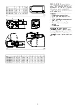
Страница 14: ...go ricambi INGOMBRO B misure indicative L ingombro del bruciatore è riportato in fig B Tener presente che per ispezionare la testa di combustione il bruciatore deve essere aperto ruotando la parte posteriore sulla cerniera L ingombro del bruciatore aperto è indicato dalle quote L e R A A B C F E D I G H R L R S S mm A B C kg RS 300 E BLU 1960 940 970 225 RS 400 E BLU 1960 940 970 236 RS 500 E BLU ...

Страница 15: ...screws M 16 x 50 1 Thermal insulation screen 4 Screws to secure the burner flange to the boiler M 18 x 70 2 Spacers see Fig C page 20 1 Pressure switch for leak detection control 1 Instruction booklet 1 Spare parts list MAX DIMENSIONS B Approximate measurements The maximum dimensions of the burner are given in B Bear in mind that inspection of the combustion head requires the burner to be opened b...

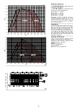
Страница 16: ...a quelle indicate dal diagramma B Se invece il bruciatore deve essere applicato ad una caldaia non omologata CE e o con dimen sioni della camera di combustione nettamente più piccole di quelle indicate dal diagramma B consultare i costruttori CALDAIA DI PROVA B I campi di lavoro sono stati ricavati in speciali caldaie di prova secondo la norma EN 676 Riportiamo in B diametro e lunghezza della came...

Страница 17: ...boiler matching does not pose any problems if the boiler is CE type approved and its combustion chamber dimensions are similar to those indicated in diagram B If the burner must be combined with a boiler that has not been CE type approved and or its com bustion chamber dimensions are clearly smaller than those indicated in diagram B consult the manufacturer TEST BOILER B The firing rates were set ...

Страница 18: ...to refratta rio 2 5 B se non vi è espressa richiesta del costruttore della caldaia FISSAGGIO DEL BRUCIATORE ALLA CALDAIA B Predisporre un adeguato sistema di solleva mento agganciandosi agli anelli 3 B dopo aver tolto le viti 7 di fissaggio del cofano 8 Infilare la protezione termica data a corredo sul boccaglio 4 B Infilare tutto il bruciatore sul foro caldaia pre cedentemente predisposto come in...

Страница 19: ...the refractory fettling 2 5 B is not required unless it is expressly requested by the boiler manufac turer SECURING THE BURNER TO THE BOILER B Create a suitable hoisting system by hooking onto the rings 3 B removing the fastening screws 7 securing the cover 8 first Slip the thermal protection standard equip ment onto the blast tube 4 B Place entire burner on the boiler hole arranged previously see...

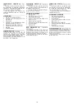
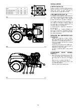
Страница 20: ...ente la cerniera a destra è obbligatorio il montaggio dei distanziali 4 fig C forniti a corredo del bruciatore solo per RS 300 400 500 E Procedere come segue fig C dopo aver svitato i dadi 2 togliere il tirante 3 svitare il distanziale 1 e posizionarlo sul foro desiderato avvitare i distanziali 4 rispettativamente sul distanziale 1 e alla vite 5 quindi rimontare tirante e dadi Per funzionamento su...

Страница 21: ...you can use a differ ent setting to that illustrated in diagram D do this by moving the tie rod onto the next highest hole numerically speaking thus increasing the combustion head s opening and hence air deliv ery If combustion requirements require you to move spacer 1 fig C onto the 1st or 2nd hole of the gear and at the same time the hinge is on the right you need to fit the spacers 4 fig C supp...

Страница 22: ...tori con potenza massima superiore a 1200 kW 9 Guarnizione 10 Farfalla regolazione gas 11 Adattatore rampa bruciatore 12 Pressostato gas di massima P1 Pressione gas alla testa di combustione P2 Pressione a monte valvole regolatore P3 Pressione a monte del filtro P4 Pressione aria alla testa di combustione vedere Fig A L Rampa gas fornita a parte con il codice indi cato in tabella C L1 A cura dell ...

Страница 23: ...r 6B Flanged Multibloc including safety valve functioning valve pressure governor 7 Minimum gas pressure switch 8 Pressure switch kit for leak detection con trol supplied separately with the code indi cated in Table C In accordance with EN 676 Standards gas valve leak detection control devices are compulsory for burners with maximum outputs of more than 1200 kW 9 Gasket 10 Gas adjustment butterfly...

Страница 24: ...13 5 18 7 7 3 9 4 4 6 5 2 2500 11 9 17 7 5 5 8 2 40 2 59 7 19 3 26 4 9 7 12 8 5 3 6 5 3000 15 9 23 7 8 0 11 9 57 8 87 3 25 7 35 0 12 5 16 8 6 4 8 3 3500 19 7 29 4 10 8 16 2 79 4 32 6 44 4 15 7 21 1 7 8 10 1 4000 22 4 33 5 14 2 21 1 104 6 40 1 54 4 19 1 25 8 9 3 12 3 4500 32 5 48 4 17 9 26 7 132 6 48 1 66 0 22 8 31 6 10 8 14 8 4590 34 3 40 2 18 6 27 2 137 7 49 5 68 2 23 5 32 8 11 1 15 3 RS 500 E BL...

Страница 25: ...m table A refers to zero in the combustion chamber to obtain true pressure measured by a U type manometer see fig A page 26 add the counter pressure of the boiler Note See the accompanying instructions for the adjustment of the gas train PRESSION DU GAZ Important La pression à la tête du brûleur tableau A se réfère à zéro dans la chambre de combustion pour obtenir la pression réelle mesurée avec u...

Страница 26: ...a spia luminosa che segnala la tensione elettrica Prima di accendere il bruciatore è opportuno regolare la rampa del gas in modo che l accen sione avvenga nelle condizioni di massima sicu rezza e cioè con una piccola portata di gas AVVIAMENTO BRUCIATORE Chiudere i termostati pressostati e mettere l interruttore 1 B in posizione MAN Verificare che le lampadine o i tester collegati alle elettrovalvo...

Страница 27: ...oid valves is equipped with a pilot light that signals voltage passing through Before starting up the burner it is good practice to adjust the gas train so that ignition takes place in conditions of maximum safety i e with gas delivery at the minimum BURNER STARTING Close thermostats pressure switches and set switch 1 B to MAN Make sure that the lamps or testers connected to the solenoids or pilot...

Страница 28: ... REGOLAZIONE ARIA PER LA MASSIMA POTENZA solo per RS 300 400 500 E BLU Regolare il servomotore alla massima apertura vicino a 90 in modo che le farfalle aria risul tino completamente aperte Allentare la vite 2 A posta sotto l aspirazione del bruciatore e chiudere progressivamente la griglia 1 A fino ad ottenere la potenza richie sta La parzializzazione in aspirazione non è neces saria solamente ne...

Страница 29: ...on the gas train AIR ADJUSTMENT FOR MAXIMUM OUTPUT only for RS 300 400 500 E BLU Set the servomotor to maximum opening near 90 so that the air butterfly valves are fully open Loosen screw 2 A under the burner s intake and close grille 1 A progressively until you achieve the required output The only time reducing intake to a partial setting is not necessary is when the burner is working at the top ...

Страница 30: ...n assoluto cioè collegato solo alla presa di pressione 22 A p 12 PRESSOSTATO GAS DI MASSIMA B Eseguire la regolazione del pressostato gas di massima dopo aver effettuato tutte le altre regolazioni del bruciatore con il pressostato gas di massima regolato a fine scala B Con il bruciatore funzionante alla potenza mas sima diminuire la pressione di regolazione girando lentamente in senso antiorario l...

Страница 31: ...s the air pressure switch is fitted in an absolute mode that is connected only to the pressure test point 22 A p 12 MAXIMUM GAS PRESSURE SWITCH B Adjust the maximum gas pressure switch after having performed all the other burner adjust ments with the pressure switch set at the end of the scale B With the burner operating at maximum output decrease adjustment pressure by slowly turning the relative...

Страница 32: ... corrente con tinua da 100 µA fondo scala Attenzione alla polarità Bruciatore Controllare che non vi siano usure anomale o viti allentate Pulire esternamente il bruciatore Combustione Qualora i valori della combustione trovati all ini zio dell intervento non soddisfino le Norme vigenti o comunque non corrispondano ad una buona combustione contattare l Assistenza Tecnica per effettuare le dovute re...

Страница 33: ...he ionisation current disconnect the plug socket on the ionisation probe cable and insert a direct current microam perometer with a base scale of 100 µA Care fully check polarities Burner Check for excess wear or loose screws Clean the outside of the burner Combustion In case the combustion values found at the beginning of the intervention do not respect the standards in force or in any case do no...

Страница 34: ...to all atto dell adde stramento del servizio di assistenza tecnica ANOMALIE RIMEDI Lo strumento in dotazione ha una sua funzione diagnostica attraverso la quale è possibile facil mente individuare le eventuali cause di mal fun zionamento Per consultare la lista completa fare riferimento al manuale specifico dello strumento fornito all atto dell addestramento del servizio di assi stenza tecnica A A...

Страница 35: ...check the full operating programme refer to the LMV instrument reference handbook sup plied during the technical service training TROUBLESHOOTING The instrument supplied features a diagnostics function through which any causes of malfunc tioning are easily identified To consult the full list refer to the instrument ref erence handbook supplied during the technical service training FONCTIONNEMENT B...

Страница 36: ...tenimento della pressione o tempe ratura della caldaia ai valori di esercizio impostati 3 la sequenza regolazione in cascata di più caldaie tramite opportuno collegamento delle varie unità e l attivazione del software interno dei singoli sistemi opzionale Ulteriori interfacce e funzioni di comunicazione con computer per telecontrollo o integrazione in sistemi di supervisione di centrale sono dispo...

Страница 37: ...ording to the load required by the system while boiler pressure or temperature is maintained at set operating values 3 a sequence cascade control of several boil ers by suitably connecting different units and activation of internal software in the individ ual systems optional item Further interfaces and computer communication functions for remote control or integration in centrally supervised syst...

Страница 38: ...tronique LMV51 10 Schema funzionale camma elettronica LMV51 Betriebsschema Elektronischer Nocken LMV51 Electronic cam LMV51 operational layout Schéma fonctionnel came électronique LMV51 11 Collegamenti elettrici kit RWF40 interno Elektroanschlüsse interner Kit RWF40 Electrical connections for internal RWF40 kit Raccordements électrique kit RWF 40 intérieur 12 Collegamenti elettrici a cura dell ins...

Страница 39: ...39 ...

Страница 40: ...40 ...

Страница 41: ...41 ...

Страница 42: ...42 ...

Страница 43: ...43 ...

Страница 44: ...44 ...

Страница 45: ...45 ...

Страница 46: ...46 ...

Страница 47: ...47 ...

Страница 48: ...48 ...

Страница 49: ...49 ...

Страница 50: ...50 ...

Страница 51: ...51 ...

Страница 52: ...52 ...

Страница 53: ...53 ...

Страница 54: ...Riello S p a declina ogni responsabilità da modifiche o collega menti diversi da quelli rappresentati in questi schemi ZEICHENERKLÄRUNG SCHEMEN A5 Elektronischer Nocken AZL Display und operative Einheit B1 Interner Leistungsregler RWF40 B2 Externer Leistungsregler RWF40 BA Fühler mit Ausgang in Strom BA1 Vorrichtung mit Ausgang in Strom für die Änderung des Fern Sollwertes BP Druckfühler BP1 Druck...

Страница 55: ...DE SCHÉMAS ELECTRIQUE A5 Came électronique AZL Unité d affichage et de réglage B1 Régulateur de puissance RWF40 intérieur B2 Régulateur de puissance RWF40 extérieur BA Sonde avec sortie en courant BA1 Dispositif avec sortie en courant pour décalage valeur de consigne à distance BP Sonde de pression BP1 Sonde de pression BR Potentiomètre valeur de consigne à distance BT1 Sonde avec thermocouple BT2...

Страница 56: ...RIELLO S p A I 37045 Legnago VR Tel 39 0442 630111 www riello it www rielloburners com Con riserva di modifiche Änderungen vorbehalten Subject modifications Sous réserve de modifications ...

Отзывы: