


19
20098582
GB
Installation
5.11.5
Hydraulic connections
The hydraulic circuit feeding system must be designed to the in-
dications provided in paragraph "Fuel supply” on page 17.
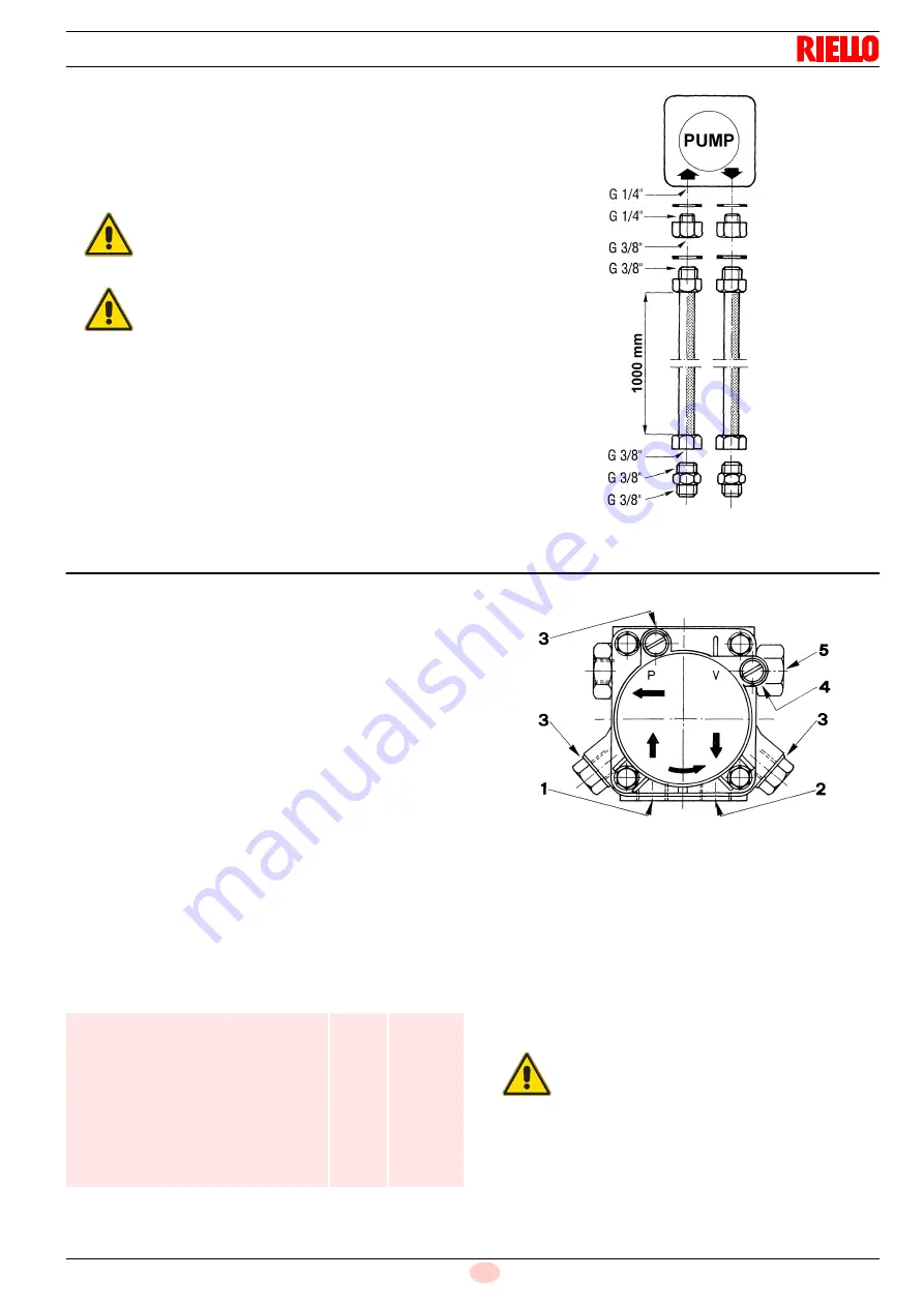
Remove the plugs from the suction and return pump connectors
and screw in the flexible hoses, the connectors, and the gaskets
provided in their place as shown in Fig. 20.
5.12
Pump
The pumps are equipped with a by-pass that connects return line
and suction line. The pumps are installed on the burner with the
by-pass closed by screw 6)(Fig. 26 on page 24).
When single-pipe fuel supply systems without degassing units
B)(Fig. 19 on page 18)
are used, this screw, accessible from the
return connector 2), must be removed. In this way, the excess in
the delivery discharged by the pressure regulator into the return
line passes into the suction line.
The pump will break immediately if it is run with the return line
closed and the by-pass screw inserted.
The vacuum meter attachment is located upstream from the
pump filter and consequently it is not able to detect a clogged fil-
ter.
The pump is delivered from the factory already full of fuel and with
its return and suction connections plugged. This stops the gear
unit rusting and permits the pump to prime upon first starting.
Water must be prevented from accumulating on the bottom of the
tank, due to infiltration or condensation, and subsequently reach-
ing the pump. Water in the pump will lead to rusting and eventu-
ally the pump will have to be renewed.
Technical data
Tab. M
Key (Fig. 21)
1
Suction
G 1/4”
2
Return
G 1/4”
3
Pressure gauge attachment
G 1/8”
4
Vacuum meter attachment
G 1/8”
5
Pressure adjustment screw:
right rotation = pressure increases
left rotation
= pressure decreases
G
cylindrical thread
The connector to be screwed into the cylindrical thread G must
be equipped with a sealing washer.
CAUTION
Make sure that the flexible hoses to the pump sup-
ply and return line are installed correctly.
Do not twist the flexible hoses during installation.
WARNING
➤
The opening of the burner or the boiler door
must not twist or strain the flexible hoses.
➤
Arrange the flexible hoses in such way that
they will never be stepped on or contact hot
boiler surfaces.
➤
Use two wrenches to screw in the flexible
hoses/nipples: one to grip the flexible hose
connector and the other to grip the nipple in
order to apply the opposite force.
Fig. 20
D413
SUNTEC AN67
Min. delivery rate at 12 bar pressure
Delivery pressure range
Max. suction depression
Viscosity range
Light oil max. temperature
Max. suction and return pressure
Pressure calibration in the factory
Filter mesh width
kg/h
bar
bar
cSt
°C
bar
bar
mm
65
10 - 18
0,45
2 - 75
60
2
12
0,150
CAUTION
Do not screw a connector with a conical thread
(NPTF) into the cylindrical thread G.
Fig. 21
D376