background image

13 

20132157

D

Installation

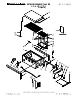
INNERE BRENNERVERDRAHTUNG (in der Fabrik fertig montiert)

C

Motorkondesator

CR

Kontaktgeber der Heizwinderstande

F

Funkentstörer

FR

Fotowinderstand

H

Störabschaltung-Fernmeldung

IN

Schalter für das manuelle Ausschalten des Brenners

K1

Relais

MB

Brenner-Klemmleiste

MV

Gebläsemotor

PS

Entriegelungtaste

R

Düsenstockwiderstand

RMO

Steuergerät

S

Vorwarmebehälter

SM

Stellmotor

TA

Zündtransformator

TB

Brenner-erdung

TE

Einstallbarer Thermostat mit Anlaufentblockung

TL

Grenzwert-Fernsteuerung

TR

Einstell-Fernsteuerung

TS

Sicherheits-Fernsteuerung

Tm

Kontaktthermostat der min. Temperatur

TM

Kontaktthermostat der max. Temperatur

V1

1° Stufe Ventil

V2

2° Stufe Ventil

ANMERKUNG:
Leiterdurchmesser: min. 1 mm

2


(Außer im Falle anderslautender Angaben durch Normen
und örtliche Gesetze).

Zweistufiger Betrieb

Man kann durch die zwischen der Klemmen 7 und 8 geschaltete
Fernsteuerung (durch Wegnehmen des Bruckes) erhalten, der
das 2. Ventil steuert.

ELEKTRISCHE ANSCHLÜSSE AN DER 
KLEMMELEISTE (vom Installateur auszuführen)

ANSCHLÜSSE DER WIDERSTÄNDE DES VORWÄRMERS

Abb. 8

A2

K1

A1

1

5

9

2

6

10

TB

R

MV

M

C

F

TE

V2

7
8
6

11

2

5

3

4
1

+

-

M

V

2
H

S

1

S

T

0

S

T

1

S

T

2

R

1

R

2

M

SM

MB

S

FR

TB

V1

CR

A1

A2

4

2

6

1 3 5


16

B

4

TA

15

12

11

5

9

18

TM

Tm

8

13

17

10

3

RMO88.53A2

1

RMO88.53A2

1

2

3

4

5

6

7

8

9

10

11 12

D2571

Abb. 9

D2572

Abb. 10

D2634

Содержание PRESS 30 N

Страница 1: ...l installation l utilisation et l entretien 20132157 1 04 2017 Bruciatori di nafta Heiz lbrenner Heavy oil burners Br leurs fioul lourd Funzionamento bistadio Zweistufiger Betrieb Two stage operation...

Страница 2: ...Istruzioni originali bersetzung der Originalen Anleitungen Translation of the original instructions Traduction des instructions d origine...

Страница 3: ...lli preliminari 9 5 4 Impianti alimentazione olio combustibile 10 5 4 1 Impianto per gravit 10 5 4 2 Impianto in aspirazione 10 5 4 3 Impianto ad anello 11 5 5 Collegamenti elettrici 12 5 5 1 Passaggi...

Страница 4: ...Tecniche EN 267 EN 12100 e secondo quanto disposto dalle Direttive Europee MD 2006 42 CE Direttiva Macchine LVD 2014 35 UE Direttiva Bassa Tensione EMC 2014 30 UE Compatibilit Elettromagnetica La qua...

Страница 5: ...tamente eseguite possono causare danni alla macchina e o alla persona PERICOLO PERICOLO COMPONENTI IN TENSIONE Questo simbolo contraddistingue operazioni che se non correttamente eseguite comportano s...

Страница 6: ...cose qualora i danni stessi si ano riconducibili ad una o pi delle seguenti cause installazione messa in funzione uso e manutenzione del bruciatore non corretti utilizzo improprio erroneo ed irragion...

Страница 7: ...lusivamente le parti previste dal costrut tore 3 2 Addestramento del personale L utente la persona o l ente o la societ che ha acquistato la macchina e che intende usarla per gli usi concepiti allo sc...

Страница 8: ...Funzionamento continuo 1 stop ogni 72 h Alimentazione elettrica del sistema 1 230 50 3 230 50 Tensione ausiliari 230 50 220 60 PRESS 30 N Testa FS1 230 50 DESIGNAZIONE BASE DESIGNAZIONE ESTESA TC 1 2...

Страница 9: ...Funzionamento Bistadio Impiego standard Caldaie ad acqua a vapore ad olio diatermico Temperatura ambiente C 0 50 Temperatura aria comburente C max 60 Pompa portata a 20 bar campo di pressione temperat...

Страница 10: ...e di blocco 8 Condensatore 9 Vite regolazione testa di combustione 10 Filtro con guaina per termometro 11 Gruppo valvole 12 Manometro con rubinetto di protezione 13 Termostato di regolazione 14 Contat...

Страница 11: ...ione del bruciatore possono essere molto pericolose se non effettua te con la massima attenzione allontanare i non addetti verificare l integrit e l idoneit dei mezzi a disposizione Ci si deve accerta...

Страница 12: ...a cisterna ad un livello inferiore del bruciatore si consiglia di far arrivare la tubazione alla stessa altezza della tubazione di aspirazione In questo caso non necessaria la valvola di fondo Rischio...

Страница 13: ...trasferimento 6 Manometro di controllo 7 Pompa bruciatore 8 Regolatore di pressione Fig 6 D2631 CAUTELA per agevolare il flusso di combustibile tutte le tu bazioni devono essere opportunamente dimen s...

Страница 14: ...riportata nella targhetta di identifica zione e nel presente manuale Il bruciatore stato omologato per funzionamento intermittente Ci significa che devono fermarsi per Norma almeno 1 volta ogni 24 or...

Страница 15: ...regolazione TS Telecomando di sicurezza Tm Termostato min nafta TM Termostato max nafta V1 Valvola 1 stadio V2 Valvola 2 stadio NOTA Sezione dei conduttori min 1 mm2 Salvo diverse indicazioni di norme...

Страница 16: ...la tabella possibile variare la pressione in pompa o com porre diversamente gli ugelli La pompa lascia la fabbrica tarata a 20 bar 6 3 Regolazione testa di combustione Si effettua ruotando la vite A F...

Страница 17: ...a superiore di quello desiderato 120 letti sulla mano pola per avere circa 100 C agli ugelli La lettura va fatta dopo qualche minuto di funzionamento poi ef fettuare i necessari ritocchi Il termostato...

Страница 18: ...nconvenienti al funzionamento del bruciatore Filtro di linea posto in aspirazione provoca l aumento della depressione in pompa con conseguente rumorosit della stessa Non supe rare un valore di depress...

Страница 19: ...s Premere pulsante per 3 s Segnale Intervallo 3 s Segnale SEGNALE CAUSA PROBABILE 2 lampeggi Non viene rilevato un segnale stabile di fiamma nel tempo di sicurezza guasto alla fotoresistenza guasto a...

Страница 20: ...rio effettuare la pulizia o la sostituzione Se all interno della pompa si notano ruggine o altre impurit aspi rare dal fondo della cisterna con una pompa separata acqua ed altre impurit eventualmente...

Страница 21: ...lettrica al bruciatore agendo sull interruttore generale dell impianto PERICOLO Chiudere il rubinetto di intercettazione del combu stibile Attendere il completo raffreddamento dei compo nenti a contat...

Страница 22: ......

Страница 23: ...8 5 Installation 9 5 1 Sicherheitshinweise f r die Installation 9 5 2 Umsetzung 9 5 3 Vorabkontrollen 9 5 4 Heiz lversorgung 10 5 4 1 Fallspeisung 10 5 4 2 Ansaugzuleitung 10 5 4 3 Ringleitung 11 5 5...

Страница 24: ...und gem den Vorgaben der Europ ischen Richtlinien MD 2006 42 EG Maschinenrichtlinie LVD 2014 35 UE Niederspannungsrichtlinie EMC 2014 30 UE Elektromagnetische Vertr glichkeit Die Qualit t wird durch...

Страница 25: ...bei falscher Ausf hrung Sch den an der Maschine und oder an Personen hervorrufen k nnen GEFAHR GEFAHR DURCH SPANNUNG F HRENDE KOMPONENTEN Dieses Symbol kennzeichnet Vorg nge die bei falscher Ausf hru...

Страница 26: ...Sachsch den die auf einen oder mehrere der folgenden Gr nde r ckf hrbar sind falsche Installation Inbetriebnahme Einsatz und Wartung des Brenners falscher fehlerhafter und unvern nftiger Einsatz des B...

Страница 27: ...Austauschbar sind nur die vom Hersteller dazu vorgesehenen Teile 3 2 Schulung des Personals Der Anwender ist die Person Einrichtung oder Gesellschaft die das Ger t gekauft hat und es f r den vorgesehe...

Страница 28: ...Halt aller 72 Std Stromversorgung des Systems 1 230 50 3 230 50 Spannung der Hilfskreise 230 50 220 60 PRESS 30 N Flammkopf FS1 230 50 GRUNDBESTIMMUNG ERWEITERTE BESTIMMUNG TC 1 230V 50Hz 3 230V 50Hz...

Страница 29: ...2 s 7 E mit Kit bis zu 150 mm2 s 20 E Betrieb Zweistufig Standardeinsatz Heizkessel mit Wasser Dampf diathermischem l Raumtemperatur C 0 50 Temperatur der Brennluft C max 60 Pumpe Durchsatz bei 20 bar...

Страница 30: ...iger 8 Kondensator 9 Schraube zur Einstellung des Brennerkopfes 10 Filter mit Schutzmantel f r das Thermometer 11 Ventilgruppe 12 Manometer mit Schutzabsperrhahn 13 Einstellbarer Thermostat 14 Kontakt...

Страница 31: ...orsicht ausgef hrt werden Entfernen Sie Unbefugte Pr fen Sie die Unversehrtheit und Eignung der zur Verf gung stehenden Mittel Au erdem muss gepr ft werden ob der Bereich in dem gearbeitet wird ber um...

Страница 32: ...der Brenner angebracht ist empfehlen wir die Leitungen des Tankes in gleicher H he wie die der Saugleitung enden zu lassen In diesem Fall ist ein Fussventil nicht n tig Explosionsgefahr durch Austrete...

Страница 33: ...enner auszuschliessen 5 F rderpumpe 6 Kontrollmanometer 7 Brennerpumpe 8 Druckregler Abb 6 D2631 VORSICHT um den Fluss des Brennstoffes zu erleichtern m ssen alle Leitungen angemessene Ausmasse haben...

Страница 34: ...zenden Betrieb homologiert Das hei t dass der Brenner vorschriftsgem mindestens 1 mal aller 24 Stunden ausgeschaltet werden muss damit das Steuerger t eine Kontrolle der Funktionst chtigkeit bei Inbet...

Страница 35: ...uerung Tm Kontaktthermostat der min Temperatur TM Kontaktthermostat der max Temperatur V1 1 Stufe Ventil V2 2 Stufe Ventil ANMERKUNG Leiterdurchmesser min 1 mm2 Au er im Falle anderslautender Angaben...

Страница 36: ...rt oder die D sen anderst zusammengestellt werden Die Pumpe verl sst die Fabrik auf 20 bar eingestellt 6 3 Einstellung des Brennerkopfes Die Einstellung erfolgt indem die Schraube A Abb 11 so gedreht...

Страница 37: ...7 E bei 50 C wir auf ca 110 C erw rmt Der Thermostat muss im allgemeinen auf einen h heren als den gew nschten Temperaturwert eingestellt werden 120 gelesen auf dem Einstellknof um bei den D sen eine...

Страница 38: ...e Zeit trocken l uft Filterreinigung muss regelm ssig ausgef hrt werden um Unannehmlichkeiten beim Brennerbetrieb zu vermeiden Filter der Speiseleitung in der Ansaugleitung verursacht er erh hten Unte...

Страница 39: ...triegelungsschalter dr cken Signal 3 s Pause Signal SIGNAL M GLICHE URSACHE 2 maliges Blinken Innerhalb der Sicherheitszeit wird keine stabile Flamme festgestellt Defekt an der Photozelle Defekt an de...

Страница 40: ...ln Sie sie aus Falls im Innern der Pumpe Rost oder andere Verunreinigungen festgestellt werden mit einer separaten Pumpe Wasser und andere eventuell abgelagerte Verschmutzungen vom Tankboden absaugen...

Страница 41: ...s Brenners durch Bet tigen des Hauptschalters der Anlage abschalten GEFAHR Das Brennstoffabsperrventil schlie en Warten Sie bis die Bauteile die mit W rmequellen in Ber hrung kommen komplett abgek hlt...

Страница 42: ......

Страница 43: ...safety for the installation 9 5 2 Handling 9 5 3 Preliminary checks 9 5 4 Fuel oil gravity feed systems 10 5 4 1 Gravity system 10 5 4 2 Suction system 10 5 4 3 Ring supply 11 5 5 Electrical wiring 1...

Страница 44: ...ing Technical Standards EN 267 EN 12100 and according to the European Directives MD 2006 42 EC Machine Directive LVD 2014 35 UE Low Voltage Directive EMC 2014 30 UE Electromagnetic Compatibility The q...

Страница 45: ...ried out correctly may cause damage to the machine and or injury to people DANGER DANGER LIVE COMPONENTS This symbol indicates operations which if not carried out correctly lead to electric shocks wit...

Страница 46: ...event of damage to things or injury to people if such damage injury was due to any of the following causes incorrect installation start up use and maintenance of the burner improper incorrect or unrea...

Страница 47: ...intenance Only those parts envisaged by the manufacturer can be replaced 3 2 Personnel training The user is the person body or company that has acquired the machine and intends to use it for the speci...

Страница 48: ...ntinuos working 1 stop every 72 h Electrical supply of the system 1 230 50 3 230 50 Auxiliary voltage 230 50 220 60 PRESS 30 N Head FS1 230 50 BASIC DESIGNATION EXTENDED DESIGNATION TC 1 230V 50Hz 3 2...

Страница 49: ...0 mm2 s 20 E with kit Operation Two stage Standard applications Boilers water steam diathermic oil Ambient temperature C 0 50 Combustion air temperature C max 60 Pump output at 20 bar pressure range f...

Страница 50: ...Capacitor 9 Regulating bush for combustion head 10 Sheathed filter for the thermometer 11 Valves group 12 Manometer with protection valve 13 Adjustment thermostat 14 Pre heater relay 15 Ignition tran...

Страница 51: ...s for the burner can be highly dangerous if not carried out with the greatest attention keep any unauthorised people at a distance check the integrity and suitableness of the available means of handli...

Страница 52: ...e pipes shall be perfectly sealead When the tank is placed below of the burner level the return pipe should reach the same level of the suction pipe In this case the foot valve is not required Explosi...

Страница 53: ...avy oil 4 Couple of cocks excluding the burner 5 Forwarding pump 6 Manometer 7 Burner pump 8 Pressure adjuster Fig 6 D2631 CAUTION all the pipes have to be properly seized sealed and heated elec resis...

Страница 54: ...shown on the identification label and in this manual The burner has been type approved for intermittent use This means they should compulsorily be stopped at least once every 24 hours to enable the co...

Страница 55: ...m Tm Min value contact thermostat TM Max value contact thermostat V1 1st stage valve V2 2nd stage valve NOTE Wires of min 1 mm2 section Unless requested otherwise by local standards and legislation Tw...

Страница 56: ...alues the pump pressure or the nozzles match could be changed The pump is set by the factory set at 20 bar 6 3 Combustion head adjustment Turn the screw A Fig 11 till the set point detected from the d...

Страница 57: ...a value higher than the required one 120 C indicated on the knob to get approximately 100 C at the nozzles The value read has to be done after some minutes of performance and later the necessary adjus...

Страница 58: ...id any trouble at the burner operation Supply line filter positioned on the suction line it causes the increase of the depression in the pump with the consequent flow of gas and noise Do not overcome...

Страница 59: ...3 s Signal SIGNAL PROBABLE CAUSE 2 flashes The flame does not stabilise at the end of the safety time faulty photocell faulty or soiled oil valves neutral phase exchange faulty ignition transformer po...

Страница 60: ...ng baskets on line 1 and at nozzle 2 present in the system Clean or replace if necessary If rust or other impurities are observed inside the pump use a separate pump to lift any water and other impuri...

Страница 61: ...Disconnect the electrical supply from the burner by means of the main system switch DANGER Turn off the fuel interception tap Wait for the components in contact with heat sources to cool down complete...

Страница 62: ......

Страница 63: ...installation 9 5 2 Manutention 9 5 3 Contr les pr liminaires 9 5 4 Alimentation en fioul 10 5 4 1 Installation par gravite 10 5 4 2 Installation en aspiration 10 5 4 3 Installation en boucle 11 5 5 B...

Страница 64: ...tes EN 267 EN 12100 et conform ment aux dispositions des directives europ ennes MD 2006 42 CE Directive Machines LVD 2014 35 UE Directive Basse Tension CEM 2014 30 UE Compatibilit lectromagn tique La...

Страница 65: ...symbole indique les op rations qui peuvent causer des dommages aux personnes ou la machine si elles ne sont pas effectu es correctement DANGER DANGER COMPOSANTS SOUS TENSION Ce symbole indique les op...

Страница 66: ...des personnes et ou des choses si ces dommages sont dus l une ou plusieurs des causes suivantes installation mise en marche utilisation ou entretien incorrects du br leur utilisation inappropri e erro...

Страница 67: ...n Les seules pi ces pouvant tre remplac es sont celles d sign es par le fabricant 3 2 Formation du personnel L utilisateur est la personne ou l organisme ou la soci t qui a achet la machine et dont l...

Страница 68: ...nnement continu 1 arr t toutes les 72 h Alimentation lectrique du syst me 1 230 50 3 230 50 Tension des auxiliaires 230 50 220 60 PRESS 30 N T te FS1 230 50 D SIGNATION DE BASE D SIGNATION TENDUE TC 1...

Страница 69: ...nctionnement Deux allures Emploi standard Chaudi res eau vapeur fioul diathermique Temp rature ambiante C 0 50 Temp rature air comburant C max 60 Pompe d bit 20 bar plage de pression temp rature du co...

Страница 70: ...t 8 Condensateur 9 Vis r gulation t te de combustion 10 Filtre avec gaine pour thermom tre 11 Groupe lectrovannes 12 Manom tre avec robinet de protection 13 Thermostat de r gulation 14 Contacteur pr c...

Страница 71: ...e manutention du br leur peuvent tre tr s dangereuses si on ne pr te pas une grande attention loigner les personnes non autoris es contr ler l int grit et l aptitude des moyens dont on dispose Il est...

Страница 72: ...i la citerne est un niveau inf rieur au br leur il est conseill de ramener la tuyauterie retour au m me niveau que celle d aspiration Dans ce cas le clapet de fond n est pas d une absolue n cessit Ris...

Страница 73: ...pe de transfert 6 Manom tre de contr le 7 Pompe br leur 8 R gulateur de pression Fig 6 D2631 PRUDENCE pour faciliter le flux du combustible toutes les tuyauteries doivent tre correctement dimensionn e...

Страница 74: ...signifie qu ils doivent s arr ter obligatoirement au moins 1 fois toutes les 24 heures pour permettre au coffret de s curit d effectuer un contr le de sa propre efficacit lors du d marrage Normalemen...

Страница 75: ...commande de s curit Tm Thermostat min fioul lourd TM Thermostat max fioul lourd V1 Vanne 1 re allure V2 Vanne 2 me allure NOTE Section conducteurs min 1 mm2 Sauf des indications diff rentes pr vues p...

Страница 76: ...ceux indiqu s dans le tableau on peut faire varier la pression de la pompe ou composer diff remment les gicleurs La pompe sort d usine tar e 25 bar 6 3 Reglage tete de combustion S effectue en tournan...

Страница 77: ...eure de celle d sir e 120 sur le thermostat pour avoir 100 C aux gicleurs La lecture sera faite apr s quelques minutes de fonctionnement faire ensuite d eventuelles retouches si necessaire Le thermost...

Страница 78: ...lmatage de celui ci provoque l augmentation de la depression dans la pompe avec pour cons quence la lib ration de gaz La pompe devient bruyante Ne pas d passer une d pression mesur e au raccord du vac...

Страница 79: ...ton pendant 3 s Signal Intervalle 3 s Signal SIGNAL CAUSE PROBABLE 2 clignotements Un signal stable de flamme n est pas d tect durant le temps de s curit anomalie de la photor sistance anomalie vannes...

Страница 80: ...installation Au besoin les nettoyer ou les remplacer En cas de pr sence de rouille ou d autres impuret s l int rieur du br leur aspirer l eau et les impuret s ventuellement d po s es au fond de la cuv...

Страница 81: ...du br leur en ap puyant sur l interrupteur g n ral de l quipement DANGER Fermer le robinet d arr t du combustible Attendre le refroidissement total des composants en contact avec des sources de chale...

Страница 82: ......

Страница 83: ......

Страница 84: ...Con riserva di modifiche nderungen vorbehalten Subject to modifications Sous r serve de modifications RIELLO S p A I 37045 Legnago VR Tel 39 0442 630111 http www riello it http www riello com...

Отзывы: