background image

2915907

GB

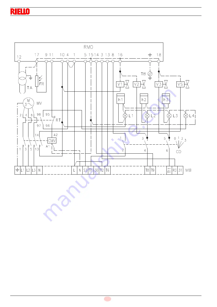
INTERNAL WIRING DIAGRAM

(carried out by the factory) 

KEY TO LAYOUT

CMV

Fan motor contactor

MB

Wiring terminal board

CO

Commutator

MV

Fan motor

FR

Photocell

RT

Thermal relay

h 1

st

  stage hourcounter

TA

Ignition transformer

h 2

nd

  stage hourcounter

TB

Burner ground (earth) connection

h 3

rd

  stage hourcounter

VS

Safety

 solenoid valve

L1

st

  stage lamp

V1

st

  stage solenoid valve

L2

nd

  stage lamp

V2

nd

  stage solenoid valve

L3

rd

  stage lamp

V3

rd

  stage solenoid valve

L4

Lock - out  motor lamp

2567

Содержание P 300 T/G

Страница 1: ...Installation use and maintenance instructions 2915907 5 02 2015 Light oil burners CODE MODEL TYPE 3478985 P300 T G 478 T80 3478986 P300 T G 478 T80 GB ...

Страница 2: ......

Страница 3: ... 1 5 E Model P300 T G Electrical supply 3 220 380V 60Hz Fan motor IE2 rpm kW V A 3500 9 2 220 380 29 1 16 8 Ignition transformer Primary 2 A Secondary 2x 6 5 kV 35 mA V Electrical intake power kW max 12 Model P300 T G Electrical supply 3 220 380V 60Hz Fan motor IE3 rpm kW V A 3540 9 2 220 380 30 5 17 6 Ignition transformer Primary 2 A Secondary 2x 6 5 kV 35 mA V Electrical intake power kW max 10 7...

Страница 4: ...Control box reset push button and lock out lamp 9 Cable clamps 10 Ignition transformer 11 Regulating bush for combustion head 12 Valves group with hydraulic jacks EQUIPMENT Flexible tubes No 2 Nipples No 2 Cable clamps No 4 Screws No 4 Extensions only long head No 2 Gasket for flange No 1 DIMENSIONS mm It is possible with a spacer upon request Fig 1 Burner Boiler front plate drilling ...

Страница 5: ...AGE POWER AND OUTPUT MINIMUM MAXIMUM kW kg h kW kg h 1st nozzle ignition phase 593 50 1186 100 1st 2nd nozzle intermediate phase 1186 100 2372 200 1s 2nd 3rd nozzle operation phase 1779 150 3558 300 2nd STAGE POWER AND OUTPUT MINIMUM MAXIMUM kW kg h kW kg h 1st nozzle ignition phase 593 50 1186 100 1st 2nd nozzle 1st stage of operation 1186 100 2372 200 1st 2nd 3rd nozzle 2nd stage of operation 17...

Страница 6: ...improved and no problems arise DIMENSIONS OF THE TESTING COMBUSTION CHAMBER in compliance with ISO 5063 1978 For the combustion head projection carefully follow the boiler manufacturer indications A proper protection with refractory material on the combustion chamber shall be made when the boilers with frontal smoke box are used D Boiler diameter in mm P Position of the boiler movable wall mm Test...

Страница 7: ... to do not overcome the max depression of 0 45 bar 35 cm Hg over this value the fuel may turn into gas Check the pipes are perfectly sealed When the fuel tank is under the burner level we suggest to let the return line arrive where the suction line starts In this case the foot valve is not necessary Should the return line arrive over the fuel level the foot valve is indispensable Notice that this ...

Страница 8: ...otocell RT Thermal relay h 1 1 st stage hourcounter TA Ignition transformer h 2 2 nd stage hourcounter TB Burner ground earth connection h 3 3 rd stage hourcounter VS Safety solenoid valve L1 1 st stage lamp V1 1 st stage solenoid valve L2 2 nd stage lamp V2 2 nd stage solenoid valve L3 3 rd stage lamp V3 3 rd stage solenoid valve L4 Lock out motor lamp 2567 ...

Страница 9: ... PS Reset push button T3 3 rd stage load control system TB Burner ground earth connection 220V 380V F A gG gL 63 50 S mm2 6 0 4 0 Check the lock out by darkening the photo cell after removal of the cover ATTENTION HIGH VOLTAGE Important In systems where the run of wiring connecting the thermostat exceeds 20 metres in length or in places where the burner is subject to particularly disturbing electr...

Страница 10: ...peration and more with only one 1st Stage 2nd Stage A Nozzles 60 Pump 12 bar 1 Total delivery kg h GPH 1st 2nd 3rd 1st 2nd 3rd 12 00 12 00 12 00 154 50 13 00 13 00 13 00 167 40 13 80 13 80 13 80 177 60 14 00 14 00 14 00 180 30 15 00 15 00 15 00 193 20 15 30 15 30 15 30 197 10 16 00 16 00 16 00 206 10 17 00 17 00 17 00 219 00 17 50 17 50 17 50 225 30 18 00 18 00 18 00 231 90 19 00 19 00 19 00 244 8...

Страница 11: ... rated at 12 bar Pay attention to not overcome the pump pressure values of 10 and 14 bar At the end on the base of the maximum output you obtain the combustion head adjustment from the diagram D The adjustment should be made by turning the screws A till the set point see diagram is on the line with the washer B Nozzles delivery Pump pressure Combustion head adjustment Maximum output Combustion hea...

Страница 12: ...urn clockwise the hexagonal body 2 in order to decrease the air flow and counterclocwise to increase it The right adjustment of the air dampers may be detect by checking the combustion results in the three stages of burner operation To check the combustion during the different stages the commutator see page 11 should be set to the position cor responding to the burner stage to be controlled 3 rd s...

Страница 13: ... operation are shown rightly on the 3rd nozzle hourcounter Commutator Pos 0 Burner stop Pos 1 Burner operation only at 1st stage Pos 2 Burner operation at 1st and 2nd stage Pos 3 Burner operation at 1st 2nd and 3rd stage Motor lock out It is caused by the overload relay in case of overload or no electric supply Push the proper reset button after removal of the protective cover 1 st nozzle hourcoun...

Страница 14: ...2 If you desire to reduce the pre purge period from 29 5 s to 16 s with contemporaneous presence of the pre ignition remove the wire from the terminal no 7 to the no 3 of the control box maintaining the bridge to the terminals 11 3 THREE STAGE OPERATION Lock out because no ignition Normal Thermostat Motor Ignition transformer 1 st flame valve 2 nd flame valve Lock out lamp Safety valve 3 rd flame ...

Страница 15: ... Key Off Yellow Green Red SIGNAL PROBABLE CAUSE 2 flashes The flame does not stabilise at the end of the safety time faulty photocell faulty or soiled oil valves neutral phase exchange faulty ignition transformer poor burner regulation insufficient gas oil 3 flashes Min air pressure switch if installed does not close air pressure switch faulty air pressure switch incorrectly regulated max air pres...

Страница 16: ...Subject to modifications RIELLO S p A I 37045 Legnago VR Tel 39 0442 630111 http www riello it http www riello com ...

Отзывы: