


5
20013744
GB
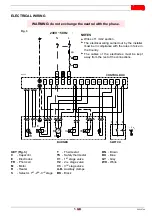
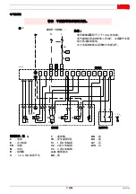
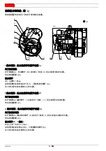
ELECTRICAL WIRING
E
1
2
3
5
6
7
8
9
10
11
12
1 2 3
1 2 3
1 2
4
1 2 3
A
B
N
L
230V
~
50Hz
TL
TS
6A
M
1
~
V1
M
V2
R
V3
N
L
BN
BU
BK
BK
W
H
BU
BU
BK
BU
BN
G
Y
BK
BN
C
FR
I II
III
D8393
CONTROL BOX
BURNER
SWITCH
Fig. 3
230V ~ 50Hz
NOTES
Wires of 1 mm2 section.
The electrical wiring carried out by the installer
must be in compliance with the rules in force in
the Country.
The cables of the electrodes must be kept
away from the rest of the connections.
KEY (Fig. 3)
C
- Capacitor
E
- Electrodes
FR
- Photocell
M
- Motor
R
- Heater
S
- Selector, 1
st
-2
nd
-3
rd
stage
T
- Thermostat
TS
- Safety thermostat
V1
- 1
st
stage valve
V2
- 2
nd
stage valve
V3
- 3
rd
stage valve
A-B
- Auxiliary clamps
BK
- Black
BN
- Brown
BU
- Blue
GY
- Grey
WH
- White
WARNING: do not exchange the neutral with the phase.
Содержание G5RT MC
Страница 14: ...20013744 CN RIELLO Technical Assistance Centre Assistance Centre Maintenance Contract...
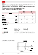
Страница 21: ...7 20013744 CN 6mm 2 1 CO2 CO2 3 1 3 0 3 2 3 6 D5587 1 5 3...
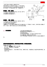
Страница 22: ...20013744 8 CN 6 1 1 9 10 1 9 10bar 4 5 2 2 2 3 1 2 3 3 6 7 1 6 2 3 15bar 8 5 1 2 3 6 7 9 10 4 5 8 D8384 6...
Страница 25: ...11 20013744 CN 1 CO2 CO ppm NOx ppm...
Страница 26: ......
Страница 27: ......


