
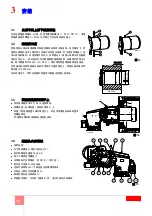


3
1
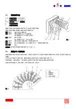
简介
1.1
命名规则说明
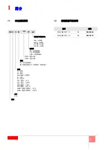
1.2
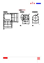
燃烧器型号及编码
DB 6
S
TC
A-0
A-0
=
从底部
A-90
=
从右侧
燃烧头
TC
=
标准燃烧头
燃料
S
=
天然气
P
= LPG
调整
E
=
电子比例调节
大小
系列
N
=
重油
NS
=
重油 / 天然气
NP
=
重油 /
LPG
NA
=
重油介质雾化
L
=
轻油
TL
=
加长燃烧头
助燃空气供应方向
NAP
=
重油介质雾化 /
LPG
M
=
机械比例调节 ( 比例调节,机械凸轮 )
LS
=
轻油 / 天然气
LP
=
轻油 /
LPG
NAS
=
重油介质雾化 / 天然气
TXL
=
特殊燃烧头
A-180
=
从上部
A-270
=
从左侧
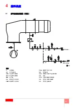
4 - 6
M
CO
CO1
=
黄色火焰
CO2
=
蓝色火焰
型号
编码
DB 4 SM CO1 TC
A0
20080068
DB 6 SM CO1 TC
A0
20075270
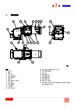
Содержание DB 6 SM CO1 A0
Страница 2: ......
Страница 43: ...1...
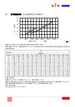
Страница 44: ...2 1 3 3 3 2 4 4 4 5 6 8 9 3 10 10 10 10 10 4 11 11 12 5 13 13 14 15 15 17 18 18 6 19 19...
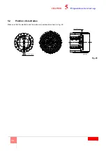
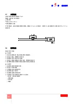
Страница 47: ...5 2 2 3 1 2 3 4 5 6 7 8 9 10 11 UV 12 13 14 15 16 17 18 19 20 21 M12x16 2 20076243...
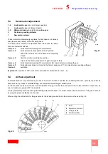
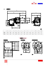
Страница 49: ...7 2 DN 80 160 18 4 54 5 4 9 5 3 8 0 M18 D8325 7 8 D3974 9 D7549 DB6 SM...
Страница 53: ...11 4 4 1 D7543 C GF HPG LPG MM PA PGM PGm RG SRV VE VPS VR VS 0 5 4 bar 500 mbar 16...
Страница 54: ...12 4 4 2 MB PA PGM SM UV UV TA TB D9854 17...
Страница 56: ...14 5 5 2 20 20 20076847...
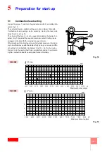
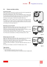
Страница 57: ...15 5 5 3 1 4 2 3 5 6 7 1 2 0 3 20 4 5 20 130 1 4 5 4 130 22 21 D1500 3 2 4 1 22 1 2 3 4 D1499...
Страница 58: ...16 5 MAN 3 1 130 90 2 22 2 22 20 2 2...
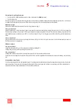
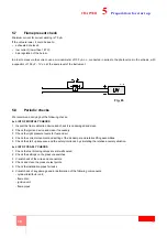
Страница 59: ...17 5 5 6 23 20 CO 1 10 000 ppm CO 1 24 2 mbar 1 mbar 25 2 mbar 1 mbar D2215 23 D3571 24 D3571 25...
Страница 60: ...18 5 5 7 70 A 187 V 100 A c c 100 F 1V c c 5 8 1 2 3 4 5 1 2 3 4 5 6 D1143 26...
Страница 61: ...19 6 6 1 1 2 3 VR VR VS VR...
Страница 62: ...20 6...
Страница 63: ......


