background image

10

CONDENSING GENERATORS

Wall-hung gas condensing modules

WATER IN THE PLANT

Before connecting the thermal module, it is necessary to clean the system. This step is absolutely required when the appliance 
replaces another one on pre-existing systems.In order to carry out this cleaning activity, if the old generator is still installed 
on the system, it is advisable to:
•  Add a de-scaling additive.
•  Operate the system with the generator on for around 7 days.
•  Discharge dirty system water and flush the system one or more times with clean water.
If the system is very dirty, repeat the last procedure one more time.In case of new installation or if the old generator is not 
present or available, use a pump to circulate the additive water in the system for  about 10 days and carry out the final washing 
as described in the previous paragraph.
Once the cleaning has been completed, it is recommended to add a suitable protective fluid to the system's water before 
installing  the thermal module.
Do not use incompatible liquid detergents, including acids (eg chloridric acid and similar) in any concentration.
Do not subject the exchanger to cyclical pressure variations because the fatigue stress is very dangerous for the integrity of the 
system components.
Sludge, limestone and contaminants present in the water can lead to irreversible damage to the heat generator, even in short 
times and regardless of the quality level of the materials used.
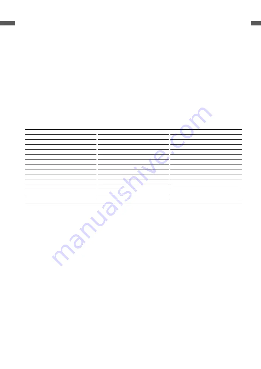
The quality of the water used in the heating system must comply with the following parameters:

Parameters

Value

Unit

General characteristic

Colorless, without sediment

PH value

Min 6.5; Max 8

PH

Dissolved oxygen

<0.05

mg / l

Total iron (Fe)

<0.3

mg / l

Total Copper (Cu)

<0.1

mg / l

Na2SO3

<10

mg / l

N2H4

<3

mg / l

PO4

<15

mg / l

CaCO3

Min 50; Max 150

ppm

Trisodium phosphate

None

ppm

Chlorine

<100

ppm

Electrical conducibility

<200

microsiemens / cm

Pressure

Min 0.6; Max 6

bar

Glycol

Max 40% (only propylene glycol)

%

All the data in the table refer to the water contained in the system after 8 weeks' operation.
Do not use excessively softened water. Excessive water softening (total hardness < 5° f) results in corrosion due to contact  with 
metal elements (pipes or thermal module components).
Immediately repair any leaks or drips that could result in air entering the system.
Excessive pressure fluctuations can cause stress and fatigue to the heat exchanger. 
Maintain a constant operating pressure.
Water used to fill a system for the first time and water used  to top it up must always be filtered (using synthetic or metal  mesh 
filters with a filtration rating of no less than 50 microns) to prevent sludge from forming and triggering deposit  corrosion. If 
oxygen enters a circuit continuously or even intermittently  (e.g. in under-floor heating systems whose pipes are not  protected 
by impermeable synthetic sheaths, in circuits with  open expansion vessels, or in circuits that require frequent  top-ups) always 
separate the boiler’s water circuit from the central heating circuit. 
It is prohibited to top up the heating system constantly or frequently, since this can damage the thermal module's  heat 
exchanger. The use of automatic topping up systems  should be avoided for this reason.

To sum up, in order to eliminate contact between air and water (and to prevent the latter from becoming oxidized), it is 
necessary:
•  that the expansion system be a closed vessel, correctly sized and with the correct pre-loading pressure (to be regularly 

checked);

•  that the system be always at a pressure higher than the  atmospheric one at any point (including the pump suction  side) 

and under any operating conditions (all seals  and hydraulic couplings in a system are designed to  withstand pressure 
towards the outside, but not underpressure);

•  the installation be not made with gas-permeable materials (e.g. plastic pipes without oxygen barrier for underfloor  

heating systems).

Damages suffered by the thermal module, caused by encrustations and corrosion, are not covered by warranty.

Содержание Condexa Pro 100 P

Страница 1: ...Wall hung gas condensing modules Stand alone installation In conformity with Directive 2009 125 EC Condensing thermal modules for indoor applications Modular design to ensure an easy and fast install...

Страница 2: ...gime times and maximizing condensation The basic electronics include climate control module cascade management with integrated master slave functions automatic summer winter switching and the possibil...

Страница 3: ...Flue gas temperature at max and min power 50 30 C C 45 0 32 0 46 0 33 0 49 0 35 0 Excess air at max power 1 27 1 27 1 27 Excess air at min power 1 27 1 27 1 27 Max min flue gas mass flow rate kg s 0 0...

Страница 4: ...gh temperature capacity 4 88 4 88 2 88 2 At 30 of useful heat output and at low temperature capacity 1 98 2 98 0 98 0 AUXILIARY ELECTRICAL CONSUMPTION At full load elmax W 105 77 203 At partial load e...

Страница 5: ...0 1 0 1 Flue flow rate kg s 0 020 0 03 0 046 GAS EMISSION VALUES AT MAX AND MIN FLOW RATES G20 MAXIMUM CO s a less than ppm 73 90 92 CO2 9 9 9 NOx EN 677 ppm 30 30 30 Flue temperature C 67 5 72 78 T...

Страница 6: ...AYOUT Condexa PRO 50 P Commercial description H mm L mm P mm fumes air mm Net weight kg CONDEXA PRO 50 P 1000 600 435 80 66 CONDEXA PRO 70 P 1000 600 435 80 78 CONDEXA PRO 100 P 1000 600 435 110 81 Fu...

Страница 7: ...11 13 14 1 2 3 4 5 6 7 8 9 10 21 19 20 22 23 16 18 24 17 1 2 3 4 5 6 7 8 9 0 7bar 10 11 12 13 14 15 16 17 18 19 20 21 22 23 24 10 9 11 12 1 2 3 4 5 6 7 8 18 22 14 20 19 21 16 15 17 23 1 3 4 5 14 2 20...

Страница 8: ...ssure switch 5 NTC return probe 6 NTC flow probe 7 Safety thermostat temperature sensor 8 Automatic bleed valve 9 Flow meter F Central heating flow R System return 2 9 M R 1 6 7 8 3 4 5 CIRCULATORS 0...

Страница 9: ...the table below DESCRIPTION Condexa PRO 50 P 70 P 100 P A mm 387 387 387 B mm 143 5 143 5 143 5 C mm 63 5 63 5 63 5 D mm 283 5 283 5 283 5 E mm 98 5 98 5 98 5 F mm 92 5 92 5 92 5 H optional 3 way valv...

Страница 10: ...6 Max 6 bar Glycol Max 40 only propylene glycol All the data in the table refer to the water contained in the system after 8 weeks operation Do not use excessively softened water Excessive water softe...

Страница 11: ...ATURE PROBE ACCESSORY The correct positioning of the external probe is fundamental for the proper functioning of the climate control The probe must be installed outside the building to be heated at ab...

Страница 12: ...25 30 10 40 60 70 50 80 90 100 T C Correspondence table valid for all probes CONTROL PANEL 2 1 3 4 5 6 7 9 8 10 1 255x80 backlit display 106 4x39 0mm 2 RESET button allows operation to be restored aft...

Страница 13: ...revent contamination do not install suction line air intakes and gas flue extraction pipes near dry cleaners laundry rooms and factories pools metallurgy processing plants beauty parlours fridge repai...

Страница 14: ...P 610 32 ACCESSORIES FOR STAND ALONE INSTALLATION GUIDE TO SYSTEM CONFIGURATION WITH STAND ALONE BOILER AND ACCESSORIES SELECTION 1 ACCESSORIES TO COMPLETE THE SYSTEM 2 OPTIONAL ACCESSORIES 2 1 Addit...

Страница 15: ...on It allows the hydraulic separation between the primary circuit and the secondary circuit balancing the differences in flow between the circuits This device is necessary on systems equipped with con...

Страница 16: ...and the hydraulic separator Frame kit for front cascades it contains all the panels and screws needed to install the boiler support frame this kit can be used for all Condexa PRO boiler range 2 3 Seco...

Страница 17: ...and 9 to allow their disposal through the common sewer system The kit is suitable for those systems equipped with a condensate drain in the thermal plant located higher than the condensate discharge o...

Страница 18: ...eturn EAF Cold water inlet UAC Domestic hot water outlet Scheme 2 circuit with thermal module connected directly to the heating system and DHW tank check that the pump head is sufficient to ensure ade...

Страница 19: ...EAF Cold water inlet UAC Domestic hot water outlet Scheme 4 circuit with thermal module connected with DHW tank and with heating system by means of hydraulic separator 1 Globe valve 2 Non return valve...

Страница 20: ...itch 9 Softener filter 10 Pressure reducer 11 Tank 12 Automatic bleed valve 13 Three way valve 14 Circulator 15 High temperature system circulator 16 Tank circulator SE External probe F High temperatu...

Страница 21: ...ed on the water circuit Safety thermostat Flowmeter capable of checking continuously the flow rate of the primary circuit and causing the appliance stop in case of insufficient flow Temperature probes...

Страница 22: ...nside the packaging the following material is provided Instruction booklet LPG conversion kit Bracket for wall fixing with dowels n 4 dowels d 10mm suitable for concrete bricks compact stone perforate...

Страница 23: ...42 630111 Fax 39 0442 630371 www riello com The manufacturer strives to continuously improve all products Appearance dimensions technical specifications standard equipment and accessories are therefor...

Отзывы: