22
INSTALLATION
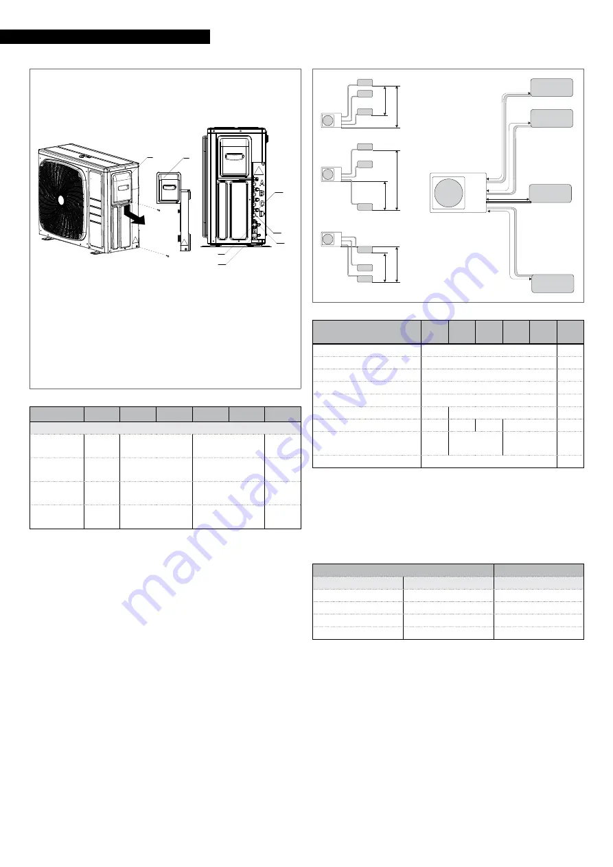
MODEL 355 - 370 - 475 - 485
1
Terminal board panel and pipes cover panel
2
Liquid valve
3
Gas valve
4
Service connection
5
Gas line connection
6
Liquid line connection
2
3
4
5
6
1
1
Model
250 P
355 P
370 P
475 P
485 P
Connections
Liquid line
connection
2 x 1/4
3 x 1/4
4 x 1/4
Inches
Gas line
connection
2 x 3/8
3 x 3/8
3 x 3/8 + 1 x 1/2 Inches
Liquid line
connection
2 x
6,35
3 x 6,35
4 x 6,35
mm
Gas line
connection
2 x
9,52
3 x 9,52
3 x 9,52 + 1 x
12,7
mm
To access the cooling connections:
—
unscrew the fastening screw
—
push down the connection covering panel
—
remove the connection covering panel
The cooling pipes must respect the lengths and differences in
height as indicated in the following table.
H+
H-
h1
h1
h2
h max
L1
L2
L3
L4
A
B
C
D
Model
250
P
355
P
370
P
475
P
485
P
h1
7,5
m
h2
7,5
m
h max
15,0
m
H-
15,0
m
H+
15,0
m
L1, L2, L3, L4
20,0
25,0
m
L1+L2+L3+L4
30,0 50,0 60,0
70,0
m
Maximum length with
standard charge
20
30
40
m
Additional charge
20
g/m
9
The R32 refrigerant gas is slightly inflammable and odour-
less. Carefully read the safety data sheet available from the
dealer and see table "Minimum floor area"
p. 9 inside
the technical data paragraph and the installation manual of
the indoor unit installed.
Use pipes with the thickness indicated in the following table:
Pipe Ø
Thickness
mm
inches
mm
6,35
1/4
0,8
9,52
3/8
0,8
12,70
1/2
0,8
15,88
5/8
1,0
Maximum operating pressure 4.3 Mpa.
9
In case of a drop in excess of 5 m, a siphon must be installed
every 5-7 metres.
9
The given measures are the maximum permitted values.
9
Cooling connections featuring shut-off valves are preconfig-
ured for flare connections.
9
Cooling lines must be as straight as possible and any neces-
sary bends must have a radius grater than 40 mm.
9
Use clean hoses. Make sure the inside is free of dust, resi-
dues, water.
Содержание AARIA MULTI 250 P
Страница 39: ......


