


20146103
14
GB
Installation
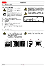
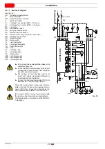
5.4
Preliminary checks
5.4.1
Control of the supply
5.4.2
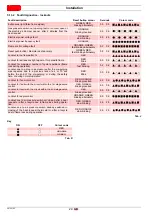
Control of burner characteristics
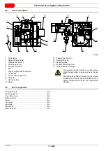
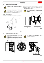
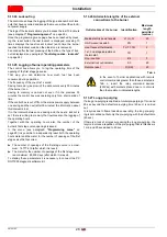
Check the identification label of the burner (Fig. 7), showing:
A
the burner model;
B
the burner type;
C
the cryptographic year of manufacture;
D
the serial number;
E
the data for electrical supply and the protection level;
F
the electrical power consumption;
G the data of the burner's minimum and maximum output pos-
sibilities (see Firing rate)
Warning.
The burner output must be within the boiler's firing
rate.
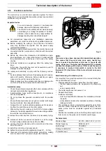
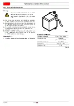
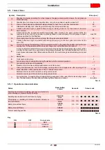
5.5
Operating position
CAUTION
After removing all the packaging, check the integ-
rity of the contents.
In the event of doubt, do not use the burner; con-
tact the supplier.
The packaging elements (cardboard box, clips,
plastic bags, etc.) must not be abandoned as they
are potential sources of danger and pollution; they
should be collected and disposed of in the appro-
priate places.
WARNING
A burner label that has been tampered with, re-
moved or is missing, along with anything else that
prevents the definite identification of the burner
makes any installation or maintenance work diffi-
cult.
WARNING
The figure of the label (Fig. 7) is indicative. Some
of the data may be arranged in a different position.
Fig. 7
20065195
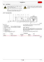
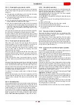
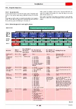
WARNING
The burner is designed to operate only in
positions
1
,
2
,
3
and
4
Installation
1
is preferable, as it is the only
one that allows the maintenance operations
as described in this manual.
Installations
2
,
3
and
4
permit operation but
make maintenance and inspection of the
combustion head more difficult.
DANGER
Any other position could compromise the cor-
rect operation of the appliance.
Installation
5
is prohibited for safety reasons.
Fig. 8
20065196
2
3
4
5
1
Содержание 40 FS5D
Страница 2: ...Translation of the original instructions...
Страница 41: ......
Страница 42: ......
Страница 43: ......