background image

21 


R

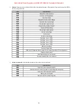
EMOTE CONTROL TERMINAL BLOCK


R

EMOTE BYPASS FOR MAINTENANCE


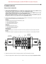
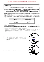
To  be  able  to  control  the  remote  maintenance  By-Pass  externally,  follow  points  1,  2  and  3  described  above.  Then 

proceed as follows: 
 

1. 

Use a 2x0.75mm

2

 cable to make the connection with the remote bypass terminals. 


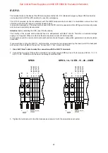
2.  Connect the two cable leads to terminals 5 and 6 (For version SPM 6), 7 and 8 (For version SPH 8 - 10 - 10 ER - 15 -

20 - 20 ER) to properly control the remote By-pass externally. 


SPM 6 

SPH 8 - 10 - 10 ER - 15 - 20 - 20 ER 


3.  Tighten the terminals well, close the back-pack and secure it with the screws taken out earlier. 
 

Note:

 The Remote Bypass function can be used with the UPS in both the single-phase and three-phase configuration. 


Call Critical Power Supplies on 0800 978 8988 for the latest information

Содержание SENTINEL POWER GREEN Series

Страница 1: ...1 Call Critical Power Supplies on 0800 978 8988 for the latest information ...

Страница 2: ...nvironmental management system developed by the company in compliance with applicable standards No hazardous materials such as CFCs HCFCs or asbestos are used in this product When evaluating packaging the choice of material has been made favouring recyclable materials For correct disposal please separate and identify the type of material of which the packaging is made in the table below Dispose of...

Страница 3: ...8 10 10 ER 14 VERSIONS SPH 15 20 20 ER 15 SETTING THE NOMINAL BATTERY CAPACITY 16 CONNECTIONS 17 SINGLE PHASE VERSION 18 COMBINED VERSION 19 SINGLE PHASE CONNECTION 19 THREE PHASE CONNECTION 20 REMOTE CONTROL TERMINAL BLOCK 21 REMOTE BYPASS FOR MAINTENANCE 21 R E P O 22 USE 23 CONNECTIONS AND SWITCHING ON FOR THE FIRST TIME 23 SWITCHING ON FROM THE MAINS 23 SWITCHING ON FROM THE BATTERY 23 SWITCHI...

Страница 4: ... 29 MONITORING AND CONTROL SOFTWARE 29 CONFIGURATION SOFTWARE 29 UPS CONFIGURATION 30 COMMUNICATION PORTS 32 RS232 CONNECTOR 32 COMMUNICATION SLOT 32 TROUBLESHOOTING 33 ALARM CODES 35 FAULT 35 LOCK 37 TECHNICAL DATA 38 Call Critical Power Supplies on 0800 978 8988 for the latest information ...

Страница 5: ...utonomy expansion units known as BATTERY BOXES optional accessories with the same dimensions and aesthetic line as the UPS alongside it The ER model UPSs fitted with upgraded battery chargers are the solution for Business Continuity applications which require long battery powered operating times For these versions the batteries are housed in separate cabinets which are designed to contain large hi...

Страница 6: ...6 UPS VIEWS FRONT VIEW ALL MODELS Display Multipurpose buttons Wheels front wheels swivel and can be locked fixed rear wheels Call Critical Power Supplies on 0800 978 8988 for the latest information ...

Страница 7: ...or maintenance Intelligent Slot Output switch Cooling fans Terminals cover backpack Parallel port optional Tie wrap hold down Battery expansion connector Earthing screws Energy Share socket Terminals for I O cable connection refer to related section Energy Share Fuse Call Critical Power Supplies on 0800 978 8988 for the latest information ...

Страница 8: ...ss for maintenance Intelligent Slot Output switch Cooling fans Terminals cover backpack Parallel port optional Tie wrap hold down Battery expansion connector Earthing screws Energy Share socket Terminals for I O cable connection refer to related section Energy Share Fuse Call Critical Power Supplies on 0800 978 8988 for the latest information ...

Страница 9: ...lligent Slot Battery expansion fuses Parallel port optional Terminals cover backpack Cooling fans Tie wrap hold down Energy Share socket Battery expansion terminals refer to related section Energy Share Fuse Earthing screws Input switch Terminals for I O cable connection refer to related section Call Critical Power Supplies on 0800 978 8988 for the latest information ...

Страница 10: ...n Load level indicator STAND BY button Configuration area Regulation operation Maintenance request Mains operation Timer Battery operation Measurement display area Load powered by bypass Stand by alarm Call Critical Power Supplies on 0800 978 8988 for the latest information ...

Страница 11: ...he type of UPS for which the BATTERY BOX is intended It is therefore necessary to take great care to ensure that the battery voltage of the BATTERY BOX is the same as the voltage permitted by the UPS It is possible to connect further BATTERY BOXES in order to create a chain suitable for achieving any autonomy time without mains power REAR VIEW Battery expansion connector Screw for earth connection...

Страница 12: ...them as shown in the figure Open the protective bag and pull it all the way down Put the previously removed slide on the back part of the pallet see figure Make sure that the slide rests firmly against the pallet so it remains in place during unloading operations Push the UPS from the front and exercise extreme caution when sliding it off the pallet NOTE All parts of the packaging should be kept f...

Страница 13: ...After opening the packaging it is first necessary to check the contents The package must contain UPS USB cable RS232 cable Slide User manual Safety manual Call Critical Power Supplies on 0800 978 8988 for the latest information ...

Страница 14: ...re for the UPS and the batteries is between 20 and 25 C The actual operating life of the batteries is 5 years on average with an operating temperature of 20 C If the operating temperature reaches 30 C the operating life is halved BATTERY BOX INSTALLATION CAUTION CHECK THAT THE BATTERY BOX VOLTAGE IS THE SAME AS THE VOLTAGE PERMITTED BY THE UPS CHECK THE RATING ON THE BACK OF THE DEVICE VERSIONS SP...

Страница 15: ...off see figure to the side 1 CONNECTION Use 3 cables with 25 mm 2 section N and 2 Connect the wires to the relative terminals following exactly the instructions given below a Make sure that the isolator of the external battery box is open b Connect the positive branch wire to terminal 11 c Connect the neutral wire to terminal 12 d Connect the negative branch wire to terminal 13 Call Critical Power...

Страница 16: ...ust be installed while the UPS is switched off and disconnected from the main CAUTION The connection cables cannot be extended by the user only for versions SPM 6 SPH 8 10 10 ER After connecting the UPS to its Battery Boxes insert the fuses and turn the Battery Box battery switches to the ON position only for versions SPH 15 20 20 ER It is not possible to connect more than one UPS to a single batt...

Страница 17: ...h conductor UPS input Differential switch Single phase Type B or Type A Three phase Type B The neutral arrangements are altered only if there is also an isolating transformer or when the UPS operates with a neutral that is disconnected upstream In any case avoid connecting the output neutral with the input neutral or to the earth as this could damage the UPS To make the mains power and load connec...

Страница 18: ...ect the neutral wire to terminal 2 d Connect the live wire to terminal 1 Output line a Connect the earth wire to screw B b Connect the neutral wire to terminal 3 c Connect the live wire to terminal 4 Remote By pass a Make sure that a jumper is connected between terminals 5 and 6 needed for proper operation of the UPS R E P O a Make sure that a jumper is connected between terminals 7 and 8 needed f...

Страница 19: ...inals following exactly the instructions below Input line a Ensure that the upstream magneto thermal switch is open b Connect the earth wire to screw A c Connect the neutral wire to terminal 4 d Connect the live wire to terminal 1 Output line a Connect the earth wire to screw B b Connect the neutral wire to terminal 5 c Connect the live wire to terminal 6 Remote By pass a Ensure that a jumper is c...

Страница 20: ...tion 25 mm 2 EARTH N and L 2 Connect the wires to the respective terminals following exactly the instructions below Input line a Ensure that the upstream magneto thermal switch is open b Connect the earth wire to screw A c Connect the neutral wire to terminal 4 d Connect the wires of the phases to terminals 1 2 and 3 for L1 use red wire Output line a Connect the earth wire to screw B b Connect the...

Страница 21: ...onnect the two cable leads to terminals 5 and 6 For version SPM 6 7 and 8 For version SPH 8 10 10 ER 15 20 20 ER to properly control the remote By pass externally SPM 6 SPH 8 10 10 ER 15 20 20 ER 3 Tighten the terminals well close the back pack and secure it with the screws taken out earlier Note The Remote Bypass function can be used with the UPS in both the single phase and three phase configura...

Страница 22: ...external voltage supply is not required When a contact is closed a maximum current of 15mA circulates All connections with the remote control terminal board are made through a cable which guarantees a double insulation connection If you would like to bring the R E P O control outside unscrew the two screws securing the lower part of the backpack and remove it as indicated in the section Connection...

Страница 23: ...lo ups com SWITCHING ON FROM THE MAINS 1 Press the ON button for 1 second After pressing it all the icons on the display light up for 1 second and the UPS beeps 1 Switch on the equipment connected to the UPS When switching on for the first time only after 30 seconds check that the UPS is operating correctly 1 Simulate a blackout by disconnecting power to the UPS 2 The load must continue to be powe...

Страница 24: ...ng Low battery pre alarm Indicates that battery autonomy is coming to an end In this condition the UPS emits a beep at regular 1 second intervals Fixed Indicates that the loads connected to the UPS are powered by the bypass Dynamic Indicates the estimated percentage charge of the batteries Dynamic Indicates the percentage of charge applied to the UPS compared with the nominal value Flashing Mainte...

Страница 25: ...are shown below GRAPHIC EXAMPLE 1 DESCRIPTION GRAPHIC EXAMPLE 1 DESCRIPTION Mains voltage Battery charge percentage Mains frequency Total battery voltage UPS output voltage Applied load percentage Output voltage frequency Current absorbed by the load Residual battery autonomy Temperature of the electronics cooling system inside the UPS Fault Alarm 2 the corresponding code is displayed Lock 2 the c...

Страница 26: ...the cooling system for the UPS internal electronics Fault Alarm 3 the corresponding code is displayed Lock 3 the corresponding code is displayed 1 The values shown in the images in the table are purely indicative 2 Alternative indication Phase No Voltage 3 The FAULT LOCK codes can only be displayed if they are active i e if there is a fault alarm or a lock 4 Alternating indication Battery branch n...

Страница 27: ...a configurable range Outside this range the UPS output de synchronises from the mains supply moving to the nominal frequency in this condition the UPS cannot use the bypass In order to optimise performance in ECO mode the load is normally powered by the bypass If the mains goes out of the permitted tolerance range the UPS switches to ON LINE operation If the mains returns within the permitted tole...

Страница 28: ...sociated with an icon on the display whose meaning is explained in the paragraph entitled Display panel indications Note The maximum output current of EnergyShare sockets is 10A PARALLEL OPERATION MODE OPTIONAL The SENTINEL POWER GREEN range makes it possible to connect up to 2 UPS units in parallel each with its own battery allowing redundancy in case of malfunction of one of the two UPS units or...

Страница 29: ...a USB or RS232 For a list of possible configurations available to the user refer to the UPS Configuration paragraph INSTALLATION OPERATIONS 1 Connect one of the UPS s communication ports to one of the PC s communication ports using the cable supplied 2 Follow the installation instructions shown within the software manual which can be located in the UPSTools directory or downloaded from the web sit...

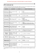
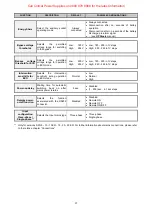
Страница 30: ...hronisation Power off due to minimum charge Automatic UPS power off in battery operation mode if the charge is lower than 5 Disabled Enabled Disabled Autonomy limit Maximum battery operation time Disabled Disabled complete battery discharge 1 65000 sec in 1 sec steps Battery low warning Estimated autonomy time remaining for the battery low warning 3 min 1 255 min in 1 min steps Battery test Interv...

Страница 31: ... Low 180 220 in 1V steps High 240 264 in 1V steps Intervention sensitivity for ECO Selects the intervention sensitivity during operation in ECO mode Normal Low Normal High Power on delay Waiting time for automatic switching back on after mains power returns 5 sec Disabled 1 255 sec in 1 sec steps Remote power on off function Selects the function associated with the RS232 connector Disabled Disable...

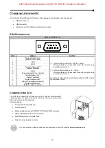
Страница 32: ...D 3 RXD 4 Programmable input default disabled 5 GND 6 Power supply DC Imax 20mA 7 Programmable input default disabled 8 Programmable output default low battery pre alarm 9 Programmable output default battery operation COMMUNICATION SLOT The UPS is equipped with an expansion slot for optional communication cards see figure on right which allows the device to communicate using the main communication...

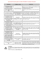
Страница 33: ...OAD IS NOT POWERED THE UPS IS IN STAND BY MODE Press the ON button on the front panel to power the loads THE STAND BY OFF MODE IS SELECTED It is necessary to change mode The STAND BY OFF emergency power supply mode in fact only powers the loads in the event of a blackout NO CONNECTION TO THE LOAD Check the connection to the load THE UPS IS OPERATING FROM THE BATTERY DESPITE THE PRESENCE OF MAINS V...

Страница 34: ...HE BUZZER SOUNDS CONTINUOUSLY AND THE DISPLAY SHOWS ONE OF THE FOLLOWING CODES F53 L53 THERE IS A FAULT ON ONE OR MORE OF THE UTILITIES POWERED BY THE UPS Disconnect all the utilities switch the UPS off and back on again reconnect the utilities one at a time to identify which one is faulty THE BUZZER SOUNDS CONTINUOUSLY AND THE DISPLAY SHOWS ONE OF THE FOLLOWING CODES F31 F33 F60 L20 L21 L22 L23 L...

Страница 35: ...om being used CODE DESCRIPTION A04 Fans blocked A12 Cable connection error A14 No neutral three phase input A15 Unbalanced input voltages three phase input A30 E P O control active A50 Overload load 105 A54 Load percentage greater than the user threshold set A62 Batteries missing or Battery Box missing or not connected A64 Low battery A90 Status of different UPS batteries parallel UPS configuratio...

Страница 36: ...tage F50 Overload load 105 F51 Overload load 110 F52 Overload load 130 F53 Overload load 150 F60 Battery overvoltage F65 Battery charge fault F92 Different UPS Bypass Status present not present parallel UPS configuration F96 Negative output power F97 Male parallel cable not connected F98 Female parallel cable not connected Active commands Indicates the presence of an active remote command CODE DES...

Страница 37: ...re L20 Capacitor bank undervoltage L21 Capacitor bank overvoltage L22 Unbalanced capacitor bank L23 Capacitor bank short circuit L24 Failed capacitor bank soft start L40 Inverter overvoltage L41 Short circuit L42 Failed inverter soft start L43 Inverter undervoltage L50 Overload load 105 L51 Overload load 110 L52 Overload load 130 L53 Overload load 150 L96 Negative output power L97 Male parallel ca...

Страница 38: ...e not available locks after 4 seconds Overload load 150 Bypass line available activates the bypass instantly locks after 1 second Bypass line not available locks after 0 5 seconds OTHER Leakage current to earth mA 1 5mA 2mA Ambient temperature 3 C 0 40 Humidity 90 without condensation Protection devices excessively low batteries overcurrent short circuit overvoltage undervoltage circuit breaker Di...

Страница 39: ...9Ah 240VDC 7Ah 240VDC 9Ah 240VDC 7 7Ah 240VDC 9 9Ah Nominal battery voltage Vdc 180Vdc 240Vdc Dimensions W x D x H mm 262 x 557 x 708 262 x 557 x 708 Weight kg 63 64 5 99 102 75 77 123 127 Call Critical Power Supplies on 0800 978 8988 for the latest information ...

Страница 40: ...Call Critical Power Supplies on 0800 978 8988 for the latest information ...

Страница 41: ...0MNSPH6K0RU5LUA Call Critical Power Supplies on 0800 978 8988 for the latest information ...
Отзывы: