- 6 -
PROFIBUS
DP
GATEWAY
CONNECTORS
AND
LEDS
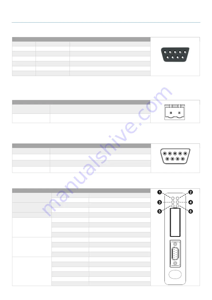
PROFIBUS
CONNECTOR
PIN
Signal
Description
5 1
9 6
(female)
Housing
Shield
Bus cable shield, connected to PE
1, 2, 7, 9
-
-
3
B-Line
Positive RxD/TxD (RS485)
4 RTS
1
Request To Send
5
GNDBUS
2
Isolated GND from RS-485 side
6 +5V
BUS
2
Is5 V output from RS-485 side (80 mA max)
8
A-Line
Negative RxD/TxD (RS485)
1
May be used by some devices to determine the direction of transmission
2
Used for bus termination; may also be used to power optical transceivers (RS485 to fibre optics)
P
OWER CONNECTOR
PIN
Description
1 2
1
+24 VDC (300 mA required)
2 GND
Note:
no power supply is provided with the device.
M
ULTI
COM
302
CONNECTOR
PIN
Description
5 1
9 6
(female)
1, 2, 3, 4, 6, 7
-
5 Signal
Ground
8
RS485+
9 RS485-
S
TATUS
LED
S
#
State
Status
1 - PROFIBUS Online
Off
Not online
Green Online
2 - PROFIBUS Offline
Off
Not offline
Red Offline
3 - (Not used)
-
-
4 - PROFIBUS
Diagnostic
Off
No diagnostics present
Red, flashing 1Hz
Error in configuration
Red, flashing 2Hz
Error in user parameter data
Red, flashing 4Hz
Error in initialization
5 - Subnet Status
Off Power
off
Green, flashing
Running correctly, but errors occurred
Green Running
Red
Subnet error
6 - Device Status
Off Power
off
Alternating Red/Green
Invalid or missing configuration
Green Initializing
Green, flashing
Running
Red Bootloader
mode
Red, flashing
Contact support department


