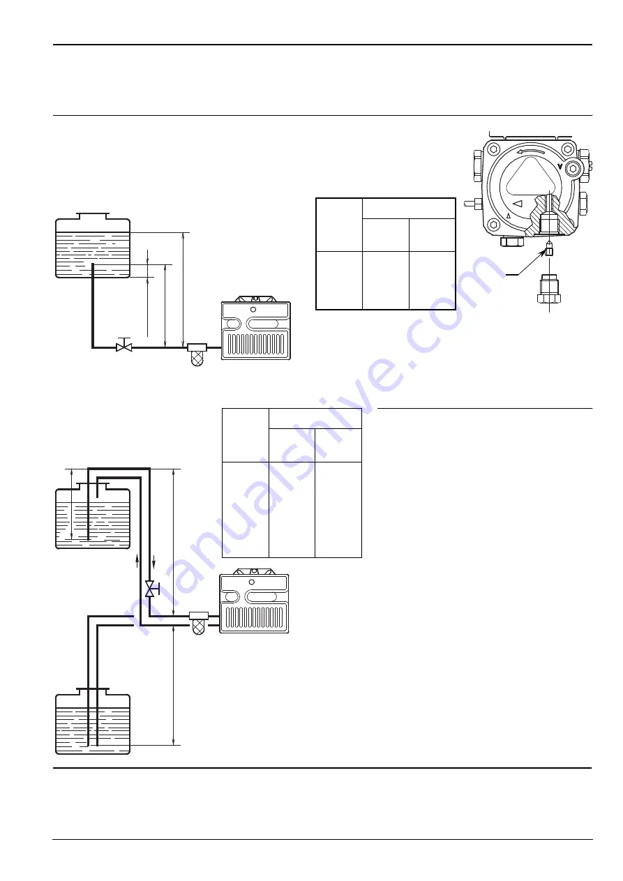
background image


2508


3


OIL LINES


Warning:


before starting the burner make sure that the return pipe-line is not clogged: any obstruc-
tion would cause the pump seals to break.

The pump vacuum should not exceed a
maximum of 0.4 bar (30 cm Hg).
Beyond this limit gas is released from
the oil.

Oil lines must be completely airtight.

The return line should terminate in
the oil tank at the same level as the
suction line
; in this case a non-return
valve is not required.

When the return line arrives over the
fuel level, a non-return valve must be
used.

This solution however is less safe than
previous one, due to the possibility of
leakage of the valve.

PRIMING THE PUMP

Start the burner and wait for the priming.
Should lock-out occur prior to the arrival
of the fuel, await at least 20 seconds
before repeating the operation.

Check periodically the flexible pipes conditions. Using kerosene, they have to be replaced at
least every 2 years.

A metal bowl filter with replaceable micronic filter must be fitted in the oil supply pipe.

H

meters

L meters

I. D.

8 mm

I.D.

10 mm

0.5

1

1.5

2

10
20
40
60

20
40
80

100

WARNING

The pump is supplied for use with a two pipe system. 
For use on a one pipe system, it is necessary to remove the by-pass
screw (A),
 (see figure).

H

meters

L meters

I. D.

8 mm

I.D.

10 mm

0

0.5

1

1.5

2
3

3.5

35
30
25
20
15

8
6

100
100
100

90
70
30
20

H

max.

 4 m

H

H

max.

 4 m

min.

 0.1 m

D5219

D5220

=

Difference of level.

L

= Max. 

length of the 

suction line.

I.D. =

Internal diameter of the

oil pipes.

PRIMING THE PUMP

Loosen the plug of the vacuum gauge (5, fig. 1,
page 1) and wait until the fuel flows out.

A

D5809

Содержание 3746686

Страница 1: ...2902508 0 Installation use and maintenance instructions Kerosene oil burner Two stage operation CODE MODEL TYPE 3746686 G10D 716T81 ...

Страница 2: ......

Страница 3: ... kV 16 mA Pump Pressure 7 15 bar Absorbed electrical power 0 2 kW 1 Return line 2 Suction line 3 Gauge connection 4 Pressure regulator 2nd stage 5 Vacuum gauge connection 6 Hydraulic jacks with air damper 7 Combustion head adjustment screw 8 Lock out lamp and reset button 9 Flange with insulating gasket 10 Regulation pressure 1st stage 11 Economizer EQUIPMENT Quantity Description 2 1 2 1 1 1 1 Fle...

Страница 4: ...0 189 83 83 170 4 5 ø 105 It is necessary that the insulating gasket 9 fig 1 is placed between the boiler door and the burner flange This insulating gasket has six holes which if necessary can be modified as shown on the drawing on the right D5242 Fig 2 Verify that the installed burner is lightly leaned towards the button See figure 2 The burner is designed to allow entry of the flexible oil lines...

Страница 5: ...Should lock out occur prior to the arrival of the fuel await at least 20 seconds before repeating the operation Check periodically the flexible pipes conditions Using kerosene they have to be replaced at least every 2 years A metal bowl filter with replaceable micronic filter must be fitted in the oil supply pipe H meters L meters I D 8 mm I D 10 mm 0 5 1 1 5 2 10 20 40 60 20 40 80 100 WARNING The...

Страница 6: ... 1 st Valve Hour counter h WARNING DO NOT EXCHANGE THE NEUTRAL WITH THE PHASE NOTES Wires of 1 mm2 section The electrical wiring carried out by the installer must be in compliance with the rules in force in the Country Connect 2nd stage thermostat between clamps T6 and T8 removing the bridge Boilers s 7 pin plug green C D A E C A D C D A C D B 2 nd Valve Terminal block of control box 530SE 4 6 3 2...

Страница 7: ...k 4 Clamps for 2nd stage thermostat 5 4 pole socket for 2nd stage thermostat 6 7 pole socket for burner N Neutral Lock out lamp L Phase Burner earth The photoresistance is fitted directly into the control box underneath the ignition trans former on a plug in support TESTING Check the shut down of the burner by opening the thermostats S7348 Ignition transformer Photoresistance S7057 ...

Страница 8: ...icated in the schedule Nozzle Pump pressure Burner output Comb head adjustment Air damper adjustment bar kg h 4 1st stage 2nd stage GPH Angle 1st 2nd 1st 2nd Set point Set point Set point 1 35 60 7 11 3 5 4 5 1 5 2 1 2 5 1 50 60 7 11 4 2 5 2 1 5 2 5 3 1 1 75 60 7 11 4 5 5 6 2 0 2 5 3 0 2 00 60 7 11 5 7 7 1 3 0 2 8 3 5 2 25 60 7 11 6 1 7 5 3 0 2 9 3 8 2 50 60 7 11 6 5 8 2 3 5 3 0 4 2 2 75 60 7 11 7...

Страница 9: ... the schedule One set point corresponds to 3 turns of the rod a hole 3 at its end facilitates counting the number of turns AIR DAMPER ADJUSTMENT The settings indicated in the schedule refer to the burner with its metal cover fitted and the combustion chamber with zero depression These regulations are purely indicative Each installation however has its own unpredictable working conditions actual no...

Страница 10: ... regulation this is set at 7 bar at the factory Should such pressure be reset or changed just turn the screw 4 The pressure gauge must be mounted in place of cap 5 2nd STAGE ADJUSTMENT Adjustment of air shutter place the small plug 9 of the economizer 10 into the position II Item B In this way the burner remains permanently in the 2nd stage Unloosen the nut 6 turn the screw 7 until the air shutter...

Страница 11: ...0 3 mm D6120 A 4 5 0 5 mm MOVE THE ELECTRODE HOLDER BACKWARDS TO THE END Attention Before assembling or remov ing the nozzle loosen the screw A and move the elec trodes ahead Normal Lock out due to light failure Thermostat Motor Ignition transformer 1st stage valve 2nd stage valve Lock out lamp 12s D5810 12s 5s 5s S7355 II I II I II I II I II I II I Position I II Burner operation in 1st or 2nd sta...

Страница 12: ......

Отзывы: