background image

29

BRENNEREINSTELLUNG

Für die optimale Einstellung des Brenners soll-
ten die Abgase am Kesselausgang analysiert
werden.

Nacheinander einstellen:
1 - Zündleistung
2 - Höchstleistung
3 - Mindestleistung
4 - Zwischenleistungen
5 - Luft-Druckwächter
6 - Gas-Höchstdruckwächter
7 - Gas-Minimaldruckwächter

1 - ZÜNDLEISTUNG
Nach Norm EN 676.

Brenner mit Höchstleistung bis 120 kW
Die Zündung kann bei der höchsten Betriebslei-
stung erfolgen. Beispiel:
• höchste Betriebsleistung 

: 120 kW

• höchste Zündleistung 

: 120 kW

Brenner mit Höchstleistung über 120 kW
Die Zündung hat bei einer verringerten Leistung
im Vergleich zur höchsten Betriebsleistung zu
erfolgen.
Falls die Zündleistung 120 kW nicht überschrei-
tet, ist keine Berechnung erforderlich. Falls die
Zündleistung dagegen 120 kW überschreitet,
legt die Norm fest, daß ihr Wert in Abhängigkeit
von der Sicherheitszeit "ts" des Steuergerätes
definiert wird:
• für ts = 2s muß die Zündleistung gleich oder

unter 1/2 der höchsten Betriebsleistung lie-
gen;

• für ts = 3s muß die Zündleistung gleich oder

unter 1/3 der höchsten Betriebsleistung lie-
gen.

Beispiel: höchste Betriebsleistung 600 kW.
Die Zündleistung muß gleich oder unter sein:
• 300 kW bei ts = 2 s
• 200 kW bei ts = 3 s

Zur Messung der Zündleistung:
- den Steckkontakt 7)(A)S.8 vom Kabel der Ioni-

sationssonde abtrennen (der Brenner schaltet
ein und geht nach der Sicherheitszeit in Stör-
abschaltung).

- 10 Zündungen mit darauffolgenden Störab-

schaltungen durchführen.

- Am Zähler die verbrennte Gasmenge able-

sen. Diese Menge muß gleich oder unter
jener sein, die durch die Formel gegeben
wird, für ts = 3 s: 

Beispiel für Gas G 20 (10 kWh/Nm

3

):

Höchste Betriebsleistung, 600 kW gleich 60 Nm

3

/h.

Nach 10 Zündungen mit Störabschaltung muß
der am Zähler abgelesene Leistung gleich oder
unter:
60 : 360 = 0,166 Nm

3

.

2 - HÖCHSTLEISTUNG
Die Höchsteistung ist im Regelbereich auf Seite
10 auszuwählen.
In der vorhergehenden Beschreibung ist der
Brenner auf der Mindestleistung in Betrieb
geblieben. Nun auf die Taste 2)(A) “Leistungs-
steigerung” drücken, bis der Stellantrieb gleich-
zeitig die Luftklappe und die Gasdrossel
geöffnet hat.
Gaseinstellung
Den Gasdurchsatz am Zähler messen.
Als Richtwert ist der Durchsatz aus den Tabellen
auf Seite 12 zu entnehmen, einfach den Gas-
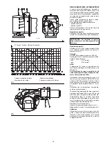
druck am U-Manometer, s. Abb. (D)S.26, able-
sen und die Hinweise auf Seite 13 befolgen.
- Falls er herabgesetzt werden muß, den Aus-

trittsgasdruck verringern, und, wenn er schon
auf dem Mindestdruckwert ist, das Regelven-
til VR etwas schließen.

- Falls er erhöht werden muß, den Austrittsgas-

druck erhöhen.

Nm

3

/h

(Höchstleistung des Brenners)

360

BURNER CALIBRATION

The optimum calibration of the burner requires
an analysis of the flue gases at the boiler outlet.

Adjust successively:
1 - First firing output
2 - MAX burner output
3 - MIN burner output
4 - Intermediate outputs between MIN and MAX
5 - Air pressure switch
6 - Maximum gas pressure switch
7 - Minimum gas pressure switch

1 - FIRING OUTPUT
According to EN 676 Regulations.

Burners with MAX output up to 120 kW
Firing can be performed at the maximum opera-
tion output level. Example:
• max. operation output 

: 120 kW

• max. firing output 

: 120 kW

Burners with MAX output above 120 kW
Firing must be performed at a lower output than
the max. operation output. If the firing output
does not exceed 120 kW, no calculations are
required. If firing output exceeds 120 kW, the
regulations prescribe that the value be defined
according to the control box safety time "ts":
• for "ts" = 2s, firing output must be equal to or

lower than 1/2 of max. operation output;

• for "ts" = 3s, firing output must be equal to or

lower than 1/3 of max. operation output.

Example: MAX operation output of 600 kW.
Firing output must be equal to or lower than:
• 300 kW with ts = 2 s
• 200 kW with ts = 3 s

In order to measure the firing output:
- disconnect the plug-socket 7)(A)p.8 on the ion-

ization probe cable (the burner will fire and
then go into lock-out after the safety time has
elapsed).

- Perform 10 firings with consecutive lock-outs.
- On the meter read the quantity of gas burned.

This quantity must be equal to or lower than
the quantity given by the formula, for ts = 3 s: 

Example for gas G 20 (10 kWh/Nm

3

):

Max. operation output: 600 kW corresponding to

60 Nm

3

/h.

After 10 firings with lock-outs, the delivery read
on the meter must be equal to or lower than:

60 : 360 = 0,166 Nm

3

.

2 - MAX. OUTPUT
Max. output of the burner must be set within the
firing rate range shown on page 10.
In the above instructions we left the burner run-
ning in MIN. output operation. Now press button
2)(A) “increase output” and keep it pressed until
the servomotor has opened the air gate valve
and the gas butterfly valve.
Gas calibration
Measure the gas delivery at the meter.
A guideline indication can be calculated from
the tables on page 12, simply read off the gas
pressure on the U-type manometer, see fig. (D)
on page 26, and follow the instructions on page
13.
- If delivery needs to be reduced, diminish out-

let gas pressure and, if it is already very low,
slightly close adjustment valve VR.

- If delivery needs to be increased, increase

outlet gas pressure.

Nm

3

/h

(max. burner delivery)

360

REGLAGE BRULEUR

Pour obtenir un réglage optimal du brûleur, il
faut effectuer l'analyse des gaz d'échappement
de la combustion à la sortie de la chaudière.

Régler en succession:
1 - Puissance à l'allumage
2 - Puissance maximum brûleur
3 - Puissance minimum brûleur
4 - Puissances intermédiaires entre les deux
5 - Pressostat air
6 - Pressostat seuil maximum du gaz
7 - Pressostat seuil minimum du gaz

1 - PUISSANCE A L'ALLUMAGE
Selon la norme EN 676.

Brûleurs avec puissance MAX jusqu'à 120 kW
L'allumage peut se faire à la puissance maxi-
mum de fonctionnement. Exemple:
• puissance max. de fonctionnement  : 120 kW
• puissance max. à l'allumage 

: 120 kW

Brûleurs avec puissance MAX au delà des 120 kW
L'allumage doit se faire à une puissance réduite
par rapport à la puissance maximum de fonc-
tionnement.
Si la puissance à l'allumage ne dépasse pas les
120 kW, aucun calcul n'est nécessaire. Au con-
traire, si la puissance à l'allumage dépasse les
120 kW, la norme établit que sa valeur soit
définie en fonction du temps de sécurité "ts" du
coffret de sécurité:
• pour ts = 2s la puissance à l'allumage doit

être égale ou inférieure à 1/2 de la puissance
maximum de fonctionnement;

• pour ts = 3s la puissance à l'allumage doit

être égale ou inférieure à 1/3 de la puissance
maximum de fonctionnement.

Exemple: puissance MAX de fonctionnement
600 kW.
La puissance à l'allumage doit être égale ou
inférieure à:
• 300 kW avec ts = 2 s
• 200 kW avec ts = 3 s

Pour mesurer la puissance à l'allumage:
- débrancher la fiche-prise 7)(A)p.8 sur le câble

de la sonde d'ionisation (le brûleur s'allume et
se bloque après le temps de sécurité).

- Exécuter 10 allumages avec blocages consé-

cutifs.

- Lire au compteur la quantité de gaz brûlée.

Cette quantité doit être égale ou inférieure à
celle donnée par la formule, pour ts = 3 s: 

Exemple pour du gaz G 20 (10 kWh/Nm

3

):

Puissance maximum de fonctionnement, 600
kW correspondants à 60 Nm

3

/h.

Après 10 allumages avec blocage le débit lu au
compteur doit être égal ou inférieur à:
60 : 360 = 0,166 Nm

3

.

2 - PUISSANCE MAXIMUM
La puissance maximum doit être choisie dans la
plage de puissance indiquée page 10.
La description ci-dessus s'entend brûleur allumé
fonctionnant à la puissance minimum. Appuyer
ensuite sur le bouton 2)(A) “augmentation de la
puissance” et continuer à appuyer jusqu’à ce
que le servomoteur ouvre le volet d’air et la
vanne papillon du gaz.
Réglage du gaz
Mesurer le débit du gaz sur le compteur.
A titre indicatif, ce débit peut être trouvé sur les
tableaux page 12. Il suffit de lire la pression du
gaz sur le manomètre en U, comme indiqué fig.
(D) page 26, et de suivre les indications p.13.
- S'il est nécessaire de la réduire, diminuer la

pression du gaz en sortie et, si elle est déjà
au minimum, fermer un peu la vanne de
réglage VR.

- S'il est nécessaire de l'augmenter, accroître la

pression du gaz en sortie.

Nm

3

/h

(débit max. brûleur)

360

Содержание 3897402

Страница 1: ...nner Blown type gas burners Br leurs gaz air souffl 2915769 1 CODE MODELE MODEL TYPE 3897402 RS 68 M BLU 846 T 3897403 RS 68 M BLU 846 T 3897602 RS 120 M BLU 847 T 3897603 RS 120 M BLU 847 T I D GB F...

Страница 2: ......
Страница 3: ...erma en bezeichnet 1 A Detail 1 der Zeichnung A auf der gleichen Textseite 1 A S 8 Detail 1 der Zeichnung A auf Seite 8 D CONTENTS TECHNICAL DATA page 6 Variants 6 Accessories 6 Burner description 9 P...

Страница 4: ...orifico inferiore kWh Nm3 Mcal Nm3 10 8 6 8 6 7 4 10 8 6 8 6 7 4 Densit assoluta kg Nm3 0 71 0 78 0 71 0 78 Portata massima Nm3 h 86 100 130 151 Pressione alla portata massima 2 mbar 11 7 17 3 22 5 33...

Страница 5: ...6 7 4 10 8 6 8 6 7 4 Reindichte kg Nm3 0 71 0 78 0 71 0 78 H chstdruchsatz Nm3 h 86 100 130 151 Druck bei H chstleistung 2 mbar 11 7 17 3 22 5 33 3 BETRIEB Intermittierend min 1 Abschaltung in 24 Std...

Страница 6: ...value kWh Nm3 Mcal Nm3 10 8 6 8 6 7 4 10 8 6 8 6 7 4 Absolute density kg Nm3 0 71 0 78 0 71 0 78 Max delivery Nm3 h 86 100 130 151 Pressure at max delivery 2 mbar 11 7 17 3 22 5 33 3 OPERATION On Off...

Страница 7: ...25 Pouvoir calorifique inf rieur kWh Nm3 Mcal Nm3 10 8 6 8 6 7 4 10 8 6 8 6 7 4 Densit absolue kg Nm3 0 71 0 78 0 71 0 78 D bit maximum Nm3 h 86 100 130 151 Pression au d bit max 2 mbar 11 7 17 3 22 5...

Страница 8: ...lla caldaia 25 Disco di stabilit fiamma 26 Staffa per l applicazione del regolatore di potenza RWF40 Vi sono due possibilit di blocco del bruciatore BLOCCO APPARECCHIATURA l accensione del pulsante de...

Страница 9: ...ir gate valve 20 Air inlet to fan 21 Screws securing fan to sleeve 22 Gas input pipework 23 Gas butterfly valve 24 Boiler mounting flange 25 Flame stability disk 26 Bracket for mounting the power regu...

Страница 10: ...su caldaie con camera di combustione a deflusso dal fondo tre giri di fumo sulle quali si ottengono i migliori risultati di basse emiessioni di NOx Lo spessore massimo del portello anteriore della ca...

Страница 11: ...are suitable for operation on either flame inversion boilers or boilers with combustion chambers fea turing flow from the base three flue passes on which the best results are obtained in terms of low...

Страница 12: ...ia alla presa 1 B fissata la potenza alla quale si desidera funzioni il bruciatore in 2 stadio Trovare nella tabella relativa al bruciatore considerato il valore di potenza pi vicino al valore desider...

Страница 13: ...on the left Example RS 68 M BLU 2nd stage operation Natural gas G 20 PCI 10 kWh Nm3 Gas ring 2 B p 16 adjusted as indicated in diagram C p 16 Gas pressure at test point 1 B 11 6 mbar Pressure in comb...

Страница 14: ...ettore graduato 8 Togliere le viti 2 dalle due guide 5 Togliere le due viti 4 ed arretrare il bruciatore sulle guide 5 per circa 100 mm Disinserire i cavi di sonda ed elettrodo e quindi sfilare del tu...

Страница 15: ...oosen the four screws 3 and remove the cover 1 Disengage the articulated coupling 7 from the graduated sector 8 Remove the screws 2 from the two slide bars 5 Remove the two screws 4 and pull the burne...

Страница 16: ...a ghiera 2 B si ottengono ridu zioni sulla formazione di NOx Continuando l esempio precedente a pag 12 si vede che per un bruciatore RS 68 M BLU con potenza di 500 kW occorrono 5 0 mbar di pres sione...

Страница 17: ...ram C indicates an optimal regulation for a type of boiler seen in fig B page 10 If the pressure of gas allows it by closing ring nut 2 B a reduction of the formation of NOx is obtained Continuing wit...

Страница 18: ...cura dell installatore LEGENDA TABELLA C C T Dispositivo controllo tenuta valvole gas 8 9 Rampa priva del dispositivo di con trollo tenuta dispositivo che pu essere ordinato a parte vedi colonna 13 e...

Страница 19: ...10 Standard issue burner gasket with flange 11 Gas adjustment butterfly valve 12 Burner 13 Gas valve 8 9 leak detection control device In accordance with EN 676 Standards gas valve leak detection cont...

Страница 20: ...sturbi LMG22 Apparecchiatura elettrica MB Morsettiera bruciatore MV Motore ventilatore PA Pressostato aria PGM Pressostato gas di massima RT Rel termico S1 Interruttore per funzionamento MAN manuale A...

Страница 21: ...out as well KEY TO LAYOUT A CMV Motor contactor F1 Protection against radio interfer ence LMG22 Control box MB Burner terminal strip MV Fan motor PA Air pressure switch PGM Maximum gas pressure switch...

Страница 22: ...ettrico per arresto manuale bruciatore MB Morsettiera bruciatore XP Spina per controllo di tenuta PG Pressostato gas di min PS Pulsante di sblocco S Segnalazione di blocco a distanza S1 Segnalazione d...

Страница 23: ...rs with VPS leak detection con trol device Gas valve leak detection control takes place immediately before every burner start up Fuses layouts B and C see table D Cross section when not indicated 1 5...

Страница 24: ...co non comprende l assorbimento di targa del motore a 400 V la protezione assicurata lo stesso Nota I modelli RS 68 120 M BLU lasciano la fabbrica previsti per alimentazione elettrica 400 V Se l ali m...

Страница 25: ...MIN If the motor is delta powered 230 V the cursor should be positioned to MAX Even if the scale of the thermal cut out does not include rated motor absorption at 400 V protec tion is still ensured i...

Страница 26: ...ciatore funzionante alla potenza MAX la farfalla del gas deve risultare tutta aperta 90 Camma I I 0 Limita la rotazione verso il minimo A bruciatore spento la serranda dell aria e la far falla del ga...

Страница 27: ...am and the gas butterfly valve It rotates through 130 degrees in 33 seconds Do not alter the factory setting for the 5 cams simply check that they are set as indicated below Cam I 130 Limits rotation...

Страница 28: ...ll accensione deve essere uguale o inferiore a 300 kW con ts 2 s 200 kW con ts 3 s Per misurare la potenza all accensione scollegare la spina presa 7 A p 8 sul cavo della sonda di ionizzazione il bruc...

Страница 29: ...urner will fire and then go into lock out after the safety time has elapsed Perform 10 firings with consecutive lock outs On the meter read the quantity of gas burned This quantity must be equal to or...

Страница 30: ...e che la variazione del profilo della camma sia progressiva Spegnere il bruciatore agendo sull interruttore 1 A p 28 posizione OFF svincolare la camma 4 A dal servomotore premendo e spostando verso de...

Страница 31: ...nfin reporter le servomoteur en position de puis sance MIN avec le bouton diminution de la puissance Pour le r glage ventuel de la came I I I surtout pour de l gers d placements on peut utiliser la cl...

Страница 32: ...ssima dopo aver effettuato tutte le altre rego lazioni del bruciatore con il pressostato gas di massima regolato a fine scala B Con il bruciatore funzionante alla potenza mas sima diminuire la pressio...

Страница 33: ...burner adjustments with the maximum gas pressure switch set to the end of the scale B With the burner operating at MAX output reduce the adjustment pressure by slowly turn ing the adjustment knob ant...

Страница 34: ...are la presenza della fiamma e la corretta posizione del pressostato aria Se la temperatura o la pressione bassa per cui il telecomando TR chiuso il bruciatore aumenta progressivamente la potenza fino...

Страница 35: ...continue cependant contr ler la pr sence de la flamme et la bonne position du pressostat de l air Si la temp rature ou la pression sont basses et que par cons quent la t l commande TR est ferm e le br...

Страница 36: ...sante 2 B p 30 Bruciatore Controllare che non vi siano usure anomale o viti allentate nei cinematismi che comandano la serranda aria e la farfalla del gas Cos pure bloccate devono essere le viti che f...

Страница 37: ...y moving the but ton 2 B p 30 to the left Burner Check for excess wear or loose screws in the mechanisms controlling the air gate valve and the gas butterfly valve Also make sure that the screws secur...

Страница 38: ...atore si avvia ma si arresta in blocco 17 Presenza di fiamma durante la preventilazione Verificare tenuta valvola 18 Guasto all apparecchiatura elettrica Sostituire apparecchiatura 7 lampeggi Il bruci...

Страница 39: ...ab schaltung an 17 Flamme bei Vorbel ftung vorhanden Dichtheit des Ventils berpr fen 18 Defekt am Steuerger t Ger t austauschen 7 maliges Blinken Der Brenner geht gleich nach der Flam menbildung in St...

Страница 40: ...replace it 5 flashes The burner starts up but halts in lock out 17 Flame presence during pre purging Check the valve tightness 18 Fault on electric control box Replace control box 7 flashes The burner...

Страница 41: ...lamme durant la pr ventilation Contr ler l tanch it de la vanne 18 Panne de la bo te lectrique Remplacer la bo te lectrique 7 clignotements Le br leur se bloque juste apr s l appari tion de la flamme...

Страница 42: ...nden Abbildung gezeigt Die Impulse der LED verursachen ein Signal das ca alle 3 Sekunden gegeben wird Die Anzahl der Impulse wird die Zeit festlegen die der F hler ab ffnung der Gasventile f r die Wah...

Страница 43: ...e Les impulsions du LED constituent un signal espac d environ 3 secondes Le nombre d impulsions indique le TEMPS DE R V LATION de la sonde d s l ouverture des vannes gaz comme d apr s le tableau suiva...

Страница 44: ...S p A Via degli Alpini 1 I 37045 Legnago VR Tel 39 0442 630111 Fax 39 0442 630375 http www rielloburners com Con riserva di modifiche nderungen vorbehalten Subject modifications Sous r serve de modifi...

Отзывы: