background image

ENGLISH

Electrical system

Chassis

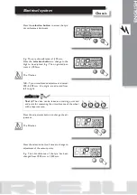
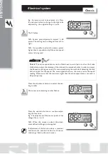
E.g.: the sensor point to be adjusted is 6. Press 
the selection button to change to the digit to be 
adjusted. E.g.: the original setting is 1 point.

The 0 flashes.

N.B.: Sensor point adjustment interval: 1~60 
points. The setting can be changed from left to 
right.

N.B.: It is possible to adjust the sensor points 
higher than 6 is possible only if the active speed 
sensor is being used.

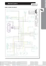
Press the adjustment button to select the set-
ting number.

The sensor points setting number flashes.

Press the selection button to continue adjus-
ting the functions.
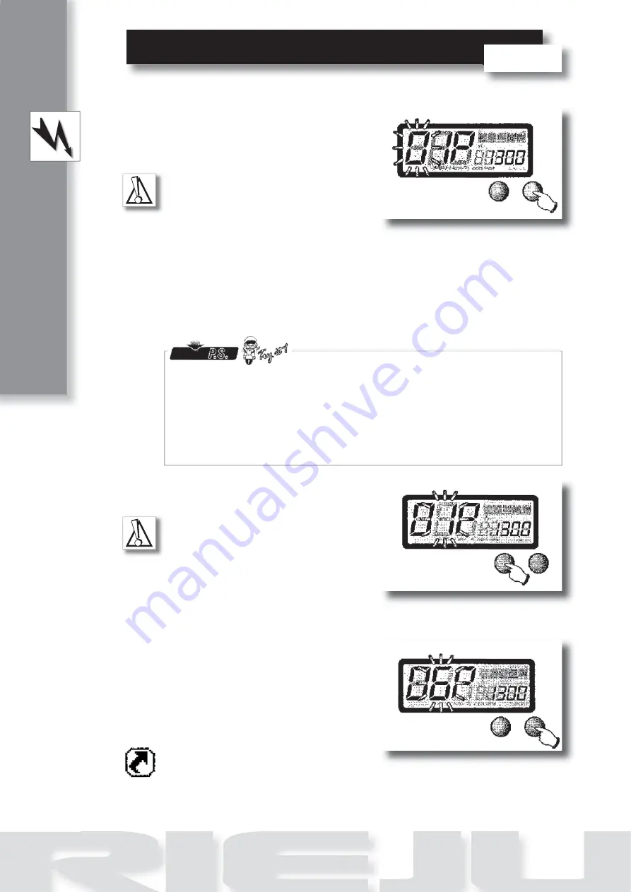
E.g.: The adjustment of the sensor points of has 
changed from 1 to 6.

N.B.: When this screen is exited, the adjust-
ment defined will begin to be applied.

If adjustment of this function alone is required, 
hold down the selection button for three se-
conds to go back to the main screen.

Test it! 

The active speed sensor can be fitted next to metal parts such as the brake 

disk bolts to detect the distance of the disk and the sprocket holder in order to detect 
the frequency of the gear teeth. We recommend using the method of detecting the disk 
bolt as a signal for the speed. The more signals there are, the more precise the speed 
reading. Please note that the maximum signal that the active speed sensor can read is 
60 points per lap.

Содержание KOSO

Страница 1: ...ator switch is moved to the left or to the right Oil temperature indicator light This indicator light comes on when the oil temperature is too high N neutral indicator light This indicator light comes on when the transmission is in the neutral position Main beam indicator light This indicator light comes on when the headlight is on main beam F 9 KOSO 1 2 3 4 ...

Страница 2: ...tors indicator To check the turn indicators indicator light connect the green cable to earth and the brown to positive Main beam indicator Connect the indicator s yellow white cable to the magneto s yellow AC cable Neutral sensor To check this sensor the circuit should be checked between the terminal and earth With the gearbox in neutral it should register 0Ω On selecting a gear the meter should r...

Страница 3: ...t km h or MPH Thermometer level indicator Interval 20 120 C 68 248 F in5levels Unitofmeasurement onelevelisequivalenttosome10 C 50 F Adjustment button Selection button Oil temperature warning When the temperature is higher than 120 C 248 F Odometer Interval 0 99 999 km miles automatic restart after 99 999 km miles Unit of measurement 1 km mile Trip meter Interval 0 999 9 km miles automatic restart...

Страница 4: ...ter and the trip meter change along with the speed measurement unit Press the selection button to continue adjus ting the function N B When this screen is exited the adjust ment defined will begin to be applied If adjustment of this function alone is required hold down the selection button for three se conds to go back to the main screen On the main screen hold down the selection and adjustment bu...

Страница 5: ...ashes N B Tyre circumference adjustment interval 300 2 500 mm the digits are adjusted from left to right Test it The valve can be taken as a starting point and end point for measuring the circumference of the wheel with a tape measure Press the adjustment button to change the ad justment The 0 flashes Press the selection button 3 times to change to adjustment of the sensor points E g The circumfer...

Страница 6: ... ting the functions E g The adjustment of the sensor points of has changed from 1 to 6 N B When this screen is exited the adjust ment defined will begin to be applied If adjustment of this function alone is required hold down the selection button for three se conds to go back to the main screen Test it The active speed sensor can be fitted next to metal parts such as the brake disk bolts to detect...

Страница 7: ...Electrical system Chassis ENGLISH KOSO WIRING DIAGRAM ...

Отзывы: