background image

Operating Instructions and Parts Manual

8

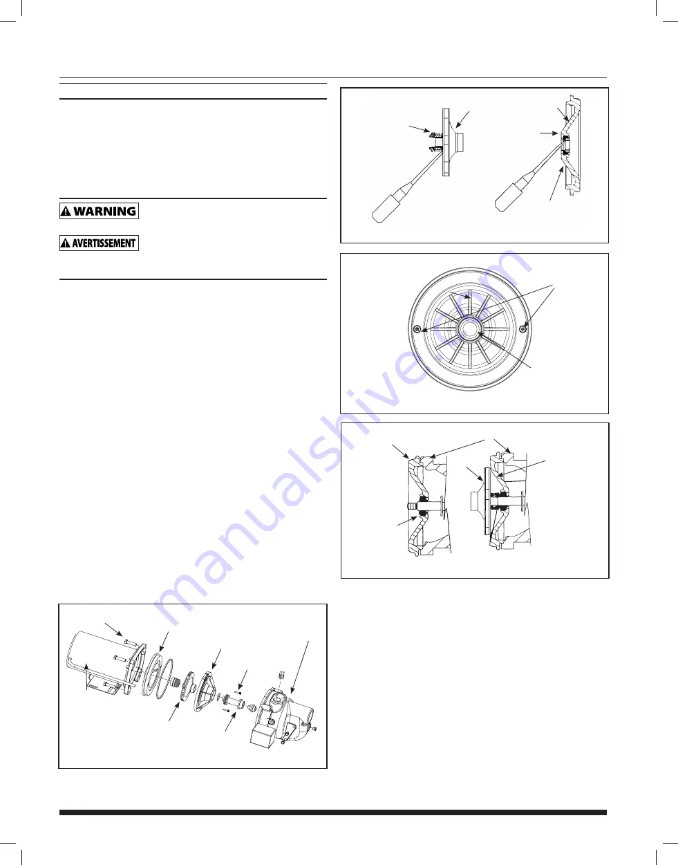
Figure 9 - Removing Shaft Seal and Ceramic Seat

ROTATING SHAFT 

SEAL MEMBER

SEAL PLATE

CERAMIC SEAT

IMPELLER

RUBBER SEAT RING

Figure 10 - Seal Plate Replacement

SCREW

MOTOR

Figure 11 - Motor Shaft

SEAL PLATE

SEAL FACE 

MUST BE 

CLEAN FOR 

PROPER SEAL

SEAL PLATE

MOTOR

IMPELLER

SEAL SEAT

KITS SECTION (CONT'D)

8.   Remove the seal plate.

9.   Pry the rotating shaft seal member (including stainless collar 

and rubber seal) from the impeller (Figure 9).

10. Push or pry the ceramic seat, and rubber seat ring free from 

the seal plate (Figure 9).

11. Remove loose particles from impeller hub and seal plate.

INSTALLING NEW SHAFT SEAL

  Before handling shaft seal parts wipe hands 

clean. Dirt or grease MAY damage the seal.

  Se laver les mains avant de manipuler les 

pièces du joint de l'arbre. La poussière ou la graisse POURRAIT 

endommager le joint.

NOTE:

 Be careful not to scratch the ceramic surface of the seal 

seat and push seat enclosed in rubber into seal cavity on seal 

plate. Use a cardboard washer to protect polished surface 

when pushing against ceramic seat with any object. Be sure to 

remove cardboard washer.

2.   Carefully slip seal plate over shaft. Do not disturb seal position 

in seal plate. The seal plate must be orientated during assembly 

so the two screw holes are on a horizontal line across the 

motor shaft (Figure 10). This placement should be done to 

ensure proper draining and priming.

3.   Place rotating shaft seal member in position on impeller and 

press into place. Take care not to press against polished seal 

surface.

4.   Position impeller on shaft and tighten securely (Figure 11).
5.   Secure diffuser to seal plate using the two cap screws. Be sure 

the arrow on the front of the diffuser is pointing up and the 

screws are orientated on a horizontal line as described in Step 

2.

6.   Carefully position pump housing (volute) gasket over the diffuser 

onto the seal plate. In all shallow well applications care must 

be taken that the o-ring is clean and properly positioned on the 

venturi. Cleaning and positioning makes a good seal inside the 

diffuser when assembled.

7.   Assemble the pump housing (volute) to the motor using the 

four cap screws. Be sure the pump housing (volute) gasket is 

positioned correctly and tighten the screws securely.

NOTE: 

Shaft must rotate freely and rear cover should be secured 

before operation.

Figure 8 - Shaft Seal

CAP SCREWS

DIFFUSER

PUMP HOUSING
(VOLUTE)

CAP SCREWS

SEAL PLATE

MOTOR

IMPELLER

VENTURI

Содержание RSWS Series

Страница 1: ...del HP PSI Discharge Head Lift Distance 0 ft 5 ft 10 ft 15 ft 20 ft 25 ft RSWS75 3 4 30 779 750 721 691 662 633 40 644 615 586 557 528 499 50 510 481 451 422 393 364 RSWS50 1 2 30 711 674 638 601 565 529 40 543 506 470 433 397 361 50 375 338 302 265 229 193 Intended for Indoor Use Only Please read and save these instructions Read carefully before attempting to assemble install operate or maintain ...

Страница 2: ...ESCRIPTION Shallow well jet pumps are single stage residential water pumps designed for pumping potable water in applications where the water is located less than 25 feet vertically from the pump A pressure switch is a standard feature The shallow well pump must be mounted to either a pre charged conventional type or free standing pressure tank Intended for indoor use only Installation of this pum...

Страница 3: ...cal circuit checked by a licensed or certified electrician to make sure the circuit is properly grounded 12 The circuit voltage and frequency of electrical current must correspond with the specifications of the motor 13 Do NOT attempt repairs to the electric motor All repairs to the motor must be completed by a licensed electrician Do NOT touch an operating motor Modern motors are designed to oper...

Страница 4: ...lling the pump Sand will damage the pumping parts and seal The draw down level of the well should not exceed the maximum rated depth for the pump The capacity of the pump will be reduced and a loss of prime may occur PIPING Inlet piping may be copper steel or rigid PVC plastic Flexible pipe is prohibited on suction pipe inlet pipe MISE EN GARDE Un tuyau flexible est interdit sur le tuyau d aspirat...

Страница 5: ... well or sand or sediment WILL be drawn into the system MISE EN GARDE Le clapet de pied DOIT au moins être à 45 7 cm 18 po du fond du puits sinon du sable ou des sédiments POURRAIENT être aspirés dans le système NOTE When a lake is used as a water supply make sure the inlet pipe is deep enough to be submerged at all times Slope the horizontal piping upward toward the pump to prevent trapping air T...

Страница 6: ...ire directly to the metal well casing or use a ground electrode furnished by the power company There is only one proper ground terminal on the unit The terminal s is located under the pressure switch cover is painted green and is identified as GRD The ground connection must be made at this terminal Figure 5 The ground conductor must not be smaller than the circuit conductors supplying the motor Di...

Страница 7: ...tank with the correct air to water ratio for the system to operate If the air volume control is good the pump will shut off at the desired cut off and will be adjusted correctly WATERLOGGED TANKS PRECHARGED If a precharged tank becomes waterlogged the bladder is normally leaking or broken 1 Test the tank by depressing the air valve The air valve will expel water if the bladder is broken 2 If broke...

Страница 8: ...ard washer 2 Carefully slip seal plate over shaft Do not disturb seal position in seal plate The seal plate must be orientated during assembly so the two screw holes are on a horizontal line across the motor shaft Figure 10 This placement should be done to ensure proper draining and priming 3 Place rotating shaft seal member in position on impeller and press into place Take care not to press again...

Страница 9: ...th new parts in reverse order 14 Wipe down the seal plate to remove any debris or loose rust 15 Push the ceramic seat of the shaft seal into the seal plate using the cardboard ring provided to keep the ceramic face clean You can use a little water or dish soap to lubricate the seal pocket to make assembly easier 16 Slide the square cut gasket over the flange on the seal plate make sure not to let ...

Страница 10: ...alve may be clogged or stuck closed 8 Pump not fully primed 9 Water level below maximum lift specification 10 Undersized piping 11 Gaseous well 12 Distorted venturi 13 Incorrect jet for application 14 Undersized pump 15 Pump cavitates sounds like pumping gravel 16 Low supply voltage 1 Lower suction pipe further into wall 2 Open faucet to allow air to vent while priming pump 3 Repair or replace to ...

Страница 11: ... or concrete to prevent cave in D DRIVEN WELL Pipe with a pointed screen is driven into the ground below the water table The depth is usually less than 50 feet Available diameters are 1 through 2 E DRILLED WELL A hole bored into the earth with machinery and lined with pipe Depths range from a few feet to over 1000 feet Common well diameters are 2 3 4 and 6 for domestic water wells F CISTERN An und...

Страница 12: ...IMPLIED WARRANTY OF MERCHANTABILITY OR FITNESS FOR ANY PARTICULAR PURPOSE AND ANY RIGHTS OR REMEDIES AGAINST ANY PERSON OR ENTITY UNDER THE UNIFORM COMMERCIAL CODE OR OTHERWISE WITH RESPECT TO THE SALE OF THE PRODUCT THE REMEDIES AND OBLIGATIONS STATED IN THIS WARRANTY ARE THE SOLE AND EXCLUSIVE REMEDIES OF AND OBLIGATIONS TO THE OWNER FOR ANY AND ALL MATTERS ARISING WITH RESPECT TO OR IN ANY WAY ...

Отзывы: