7 - English
OPERATION
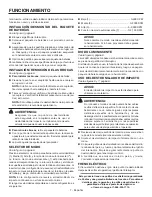
INSTALLING / REMOVING BATTERY PACK
See Figure 3, page 9.
Lock the switch trigger.
Insert the battery pack into the product as shown.
Make sure the latches on each side of the battery
pack snap in place and battery pack is secured before
beginning operation.
Depress the latches to remove the battery pack.
For complete charging instructions, see the operator’s manu-
als for your battery pack and charger.
INSTALLING / REMOVING BITS
See Figure 4, page 9.
To install bits
, remove the battery pack from the tool.
Push the bit into the coupler until it clicks into place.
NOTE:
If the bit does not insert easily into the coupler,
pull the coupler forward and reinsert the bit.
Pull on the bit to make sure it is secured in the coupler.
There may be some play in the installed bit; this is normal.
NOTE:
Use only impact quality bits with a locking groove.
WARNING:
Make sure the bit is secured in the coupler before
using the impact driver. Failure to do so could
cause serious personal injury.
To remove bits
, remove the battery pack from the tool.
With the nose of the tool pointed away from you, pull the
coupler away from the driver.
The bit will eject from the coupler.
MODE SELECTOR
See Figure 5, page 9.
Press the mode selector to cycle between Low (1) speed,
Medium (2) speed, High (3) speed, and Self-tapping
Mode ( ).
The self-tapping mode ( ) function is designed to reduce
screw stripping, screw breakage, and damage to work
surfaces when driving self-tapping screws. When driving
fasteners (forward setting), the impact driver will start fast
to drive the fastener through the workpiece and then slow
the speed to finish.
NOTE:
In the reverse setting, the impact driver will resume
normal operation.
The range of speeds available in each setting are:
Low (1) .......................................................... 0-900 RPM
Medium (2) ................................................... 0-2,000 RPM
High (3)....................................................... 0-2,900 RPM
Self-Tapping Mode ( ) ..............................0-2,150 RPM
NOTICE:
The impact driver is not designed to be used as
a drill.
LED LIGHT
See Figure 5, page 9.
The LED light located on the front of the tool base illuminates
when the switch trigger is depressed.
If the tool is not in use, the time-out feature will cause the
light to start fading and then shut off.
The LED light illuminates only when there is a charged battery
pack in the tool.
USING THE IMPACT DRIVER
See Figures 6 - 7, page 9.
NOTICE:
The impact driver is not designed to be used as
a drill.
WARNING:
Do not drive a screw where there is likely to be
hidden wiring behind the surface. Contact with a
“live” wire will make exposed metal parts of the tool
“live” and possibly shock the operator. If you must
drive a screw where hidden wire may be present,
always hold tool by insulated gripping surfaces
(handle) when performing the operation to prevent
a shock to the operator.
Check the direction of rotation selector for the correct
setting (forward or reverse).
Hold the impact driver with one hand.
Place the bit on the screw head, bolt head, or nut and
slowly depress the switch trigger. Start the bit slowly for
more control.
As the screw, bolt, or nut is driven, impacting will begin.
ELECTRIC BRAKE
The electric brake will stop the bit rotation after the operator
releases the switch trigger.
NOTE: MAINTENANCE INFORMATION BEGINS ON
PAGE 8 AFTER FRENCH AND SPANISH LANGUAGE
SECTIONS. ILLUSTRATIONS START ON PAGE 9.
This product has a 90-Day Satisfaction Guarantee Policy,
as well as a Three-year Limited Warranty. For Warranty
and Policy details, please go to powertools.ridgid.com
or call (toll free) 1-866-539-1710.
Содержание R872311
Страница 22: ...NOTES NOTAS...
Страница 23: ...NOTES NOTAS...


