RIDGID R86011 Скачать руководство пользователя страница 5

5 - English

ASSEMBLY

WARNING:

Do not use this product if it is not completely 
assembled or if any parts appear to be missing or 
damaged. Use of a product that is not properly and 
completely assembled or with damaged or missing 
parts could result in serious personal injury.

WARNING:

Do not attempt to modify this product or create ac-
cessories or attachments not recommended for use 
with this product. Any such alteration or modifica-
tion is misuse and could result in a hazardous con-
dition leading to possible serious personal injury.

If any parts are damaged or missing, please call 1-866-539-1710 for assistance.

OPERATION

WARNING:

Do not allow familiarity with tools to make you 
careless. Remember that a careless fraction of a 
second is sufficient to inflict severe injury.

WARNING:

Always remove battery pack from the tool when 
you are assembling parts, making adjustments, 
cleaning, or when not in use. Removing battery 
pack will prevent accidental starting that could 
cause serious personal injury.

WARNING:

Always wear eye protection with side shields 
marked to comply with ANSI Z87.1. Failure to do 
so could result in objects being thrown into your 
eyes, resulting in possible serious injury.

WARNING:

Do not use any attachments or accessories not 
recommended by the manufacturer of this product. 
The use of attachments or accessories not recom-
mended can result in serious personal injury.

APPLICATIONS

You may use this tool for the purposes listed below:

 

Driving nuts and bolts using an impact socket

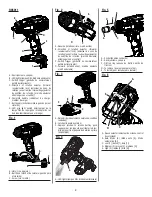
INSTALLING/REMOVING BELT HOOK

See Figure 1, page 8

.

The belt hook may be installed on either side of the housing.

  Align hole in belt hook with hole in the housing.

  Install screw to secure belt hook in place.

  To uninstall, remove screw then remove belt hook.

VARIABLE SPEED SWITCH TRIGGER

See Figure 2, page 8.

The variable speed switch trigger delivers higher speed with 
increased trigger pressure and lower speed with decreased 
trigger pressure.
To turn the tool 

ON

, depress the switch trigger. To turn it 

OFF

, release the switch trigger and allow the anvil to come 

to a complete stop.

NOTE:

  A whistling or ringing noise coming from the switch 

during use is a normal part of the switch function.

DIRECTION OF ROTATION SELECTOR

(FORWARD/REVERSE/CENTER LOCK)

See Figure 2, page 8.

Set the direction of rotation selector in the OFF (center lock) 
position to lock the switch trigger and help prevent accidental 
starting when not in use.
Position the direction of rotation selector to the left of the 
switch trigger for forward operation. Position the selector to 
the right of the switch trigger to reverse the direction.

NOTE: 

The tool will not run unless the direction of rotation 

selector is pushed fully to the left or right.


NOTICE:

To prevent gear damage, always allow the anvil 
to come to a complete stop before changing the 
direction of rotation.

WARNING:

Battery tools are always in operating condition. 
Lock the switch when not in use or carrying at your 
side, when installing or removing the battery pack, 
and when installing or removing sockets.

INSTALLING/REMOVING BATTERY PACK

See Figure 3, page 8.

  Lock the switch trigger.

  Insert the battery pack into the product as shown.

Содержание R86011

Страница 1: ...3 Symboles 4 Caract ristiques 4 Assemblage 5 Utilisation 5 7 Entretien 7 Illustrations 8 9 Commande de pi ces et d pannage Page arri re NDICE DE CONTENIDO Advertencias de seguridad para herramientas...

Страница 2: ...g Ensure the switch is in theoff positionbeforeconnectingtopowersourceand or battery pack picking up or carrying the tool Carrying power tools with your finger on the switch or energizing power tools...

Страница 3: ...s in contact with your skin wash immediately with soap and water If liquid gets into your eyes flush them with clean water for at least 10 minutes then seek immediate medical attention Following this...

Страница 4: ...or disposal options V Volts Voltage min Minutes Time Direct Current Type or a characteristic of current no No Load Speed Rotational speed at no load min Per Minute Revolutions strokes surface speed o...

Страница 5: ...ing an impact socket INSTALLING REMOVING BELT HOOK See Figure 1 page 8 The belt hook may be installed on either side of the housing Align hole in belt hook with hole in the housing Install screw to se...

Страница 6: ...unning Doing so may result in serious damage to the tool OPERATING THE IMPACT WRENCH See Figures 7 8 page 9 CAUTION The metal surface may become hot during use Avoid contact with it to avoid possible...

Страница 7: ...rs porter une protection oculaire L quipement de s curit tel qu un masque filtrant de chaussures de s curit d un casque ou d une protection auditive utilis dans des conditions appropri es r duira le r...

Страница 8: ...rincer imm diatement la partie atteinte avec de l eau En cas d claboussure dans les yeux les rincer l eau fra che pendant au moins 10 minutes puis contacter imm diatement un m decin Le respect de cett...

Страница 9: ...e les risques SYMBOLE NOM D SIGNATION EXPLICATION Symbole d alerte de s curit Indique un risque de blessure potentiel Lire le manuel d utilisation Pour r duire les risques de blessures l utilisateur d...

Страница 10: ...NTURE Voir la figure 1 page 8 Il est possible de fixer le crochet de ceinture d un c t ou de l autre du logement Aligner le trou du crochet de ceinture avec le trou du logement Installer le vis pour f...

Страница 11: ...des dommages graves l outil UTILISATION DE LA CL CHOCS Voir la figure 7 et 8 page 9 ATTENTION Les parties m talliques de l outil peuvent chauffer pendant l utilisation viter d y toucher pour viter les...

Страница 12: ...otros Siempre p ngase protecci n ocular El uso de equipo protector como mascarilla para el polvo calzado de seguridad casco y protecci n para los o dos en las circunstancias donde corresponda disminuy...

Страница 13: ...de esta regla se reduce el riesgo de lesiones corporales serias Guarde estas instrucciones Cons ltelas con frecuencia y empl elas para instruir a otras personas que puedan utilizar esta herramienta S...

Страница 14: ...peligro posible de lesiones personales Lea el manual del operador Para reducir el riesgo de lesiones el usuario debe leer y comprender el manual del operador antes de usar este producto Protecci n ocu...

Страница 15: ...INTUR N Vea la figura 1 p gina 8 El gancho del cintur n se puede usar en cualquiera de los dos lados del alojamiento Alinee el orificio de gancho del cintur n con el orificio de base Coloque el tornil...

Страница 16: ...cesiva Permite un control mayor lo que reduce el da o en los tornillos pasadores y en las superficies de trabajo En Modo autom tico la herramienta se apagar autom ticamente una vez que empiece a impac...

Страница 17: ...dommager l produit ENTRETIEN G N RAL viter d utiliser des solvants pour le nettoyage des pi ces en plastique La plupart des mati res plastiques peuvent tre endommag es par divers types de solvants du...

Страница 18: ...delante atr s seguro en el centro C Switch trigger g chette de commutateur gatillo del interruptor D Forward rotation avant marcha adelante marcha adelante Fig 3 A Raised ribs paulements sur lev s cos...

Страница 19: ...9 RIGHT CORRECT FORMA CORRECTA Fig 8 Fig 7 WRONG INCORRECT FORMA INCORRECTA...

Страница 20: ...pi ces ou pour un d pannage ne pas retourner ce produit au magasin Contacter le centre de r parations RIDGID agr le plus proche Veiller fournir toutes les informations pertinentes lors de tout appel...

Отзывы: