background image

3

ance at all times.

Proper footing and balance enables

better control of the tool in unexpected situations.

Use safety equipment. Always wear eye protection.

Dust mask, non-skid safety shoes, hard hat, or hearing
protection must be used for appropriate conditions.

Tool Use and Care

Do not use tool if switch does not turn it ON or
OFF.

Any tool that cannot be controlled with the switch

is dangerous and must be repaired.

Disconnect the plug from the power source before
making any adjustments, changing accessories,
or storing the tool.

Such preventive safety mea-

sures reduce the risk of starting the tool accidentally.

Store idle tools out of the reach of children and
other untrained persons.

Tools are dangerous in

the hands of untrained users.

Check for misalignment or binding of moving
parts, breakage of parts, and any other condition
that may affect the tool's operation. If damaged,
have the tool serviced before using.

Many acci-

dents are caused by poorly maintained tools.

Use only accessories that are recommended for
your tool.

Ac cessories that may be suitable for one tool

may become hazardous when used on another tool.

Keep handles dry and clean; free from oil and
grease.

Allows for better control of the tool.

Service

Tool service must be performed only by qualified
repair personnel.

Service or maintenance performed

by unqualified repair personnel could result in injury.

When servicing a tool, use only identical replace-
ment parts. Follow instructions in the Maintenance
Section of this manual.

Use of unauthorized parts or

failure to follow maintenance instructions may create a
risk of electrical shock or injury.

Specific Safety Information

WARNING

Read this operator’s manual carefully before using
the 535 Threading Machine. Failure to understand
and follow the contents of this manual may result in
electrical shock, fire and/or serious personal injury.

Call the Ridge Tool Company, Technical Service
Department at (800) 519-3456 if you have any questions.

Foot Switch Safety

Using a threading machine without a foot switch
increases the risk of serious injury. A foot switch
provides better control by letting you shut off the
motor by removing your foot. If clothing should
become caught in the machine, it will continue to
wind up, pulling you into the machine. Because the
machine has high torque, the clothing itself can bind
around your arm or other body parts with enough
force to crush or break bones.

Machine Safety

Threading Machine is made to thread and cut
pipe or bolt and to power roll grooving equip-
ment. Follow instructions on proper use of this
machine. Do not use for other purposes such
as drilling holes or turning winches.

Other uses or

modifying this power drive for other applications may
increase the risk of serious injury.

Secure machine to bench or stand. Support long
heavy pipe with pipe supports.

This practice will

prevent tipping.

Do not wear gloves or loose clothing when oper-
ating machine. Keep sleeves and jackets buttoned.
Do not reach across the machine or pipe.

Clothing

can be caught by the pipe or machine resulting in
entanglement and serious injury.

Operate machine from side with REV/OFF/FOR
switch.

Eliminates need to reach over the machine.

Do not use this machine if the foot switch is bro-
ken or missing.

Foot switch is a safety device to

prevent serious injury.

Keep hands away from rotating pipe and fittings.
Stop the machine before wiping pipe threads or
screwing on fittings. Allow the machine to come to
a complete stop before touching the pipe or
machine chucks.

This practice will prevent entan-

glement and serious injury.

Do not use this machine to make or break fittings.

This practice is not an intended use of the machine and
can result in serious injury.

Tighten chuck handwheel and engage rear cen-
tering device on the pipe before turning on the
machine.

Prevents oscillation of the pipe.

Keep covers in place. Do not operate the ma chine
with covers removed.

Exposure to moving parts may

result in entanglement and serious injury.

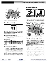
Lock foot switch when machine is not in use
(Figure 1).

Avoids accidental starting.

535 Manual Pipe and Bolt Threading Machine

WARNING

www.

.com

[email protected]

1.800.561.8187

Содержание 535 Manual Chuck

Страница 1: ...ág 33 WARNING Read this Operator s Manual carefully before using this tool Failure to understand and follow the contents of this manual may result in electrical shock fire and or serious personal injury Threading MachineManual www com information itm com 1 800 561 8187 ...

Страница 2: ...e with No 341 Reamer 8 Threading Pipe or Rod with Quick Opening Self Opening or Semi Automatic Die Head 8 Removing Pipe From the Threading Machine 9 Left Hand Threading 9 Installing Dies in Quick Opening Die Head Right Hand Left Hand 9 Installing Dies in Self Opening Die Head Right Hand Only 9 Installing Dies in Model 816 817 Die Heads 10 Checking Thread Length 10 Priming Oil Pump 11 Accessories A...

Страница 3: ... and Bolt Threading Machine Record Serial Number below and retain product serial number which is located on nameplate Serial No 535 Manual Pipe and Bolt Threading Machine 535 www com information itm com 1 800 561 8187 ...

Страница 4: ...NG Read and understand all instructions Failure to follow all instructions listed below may result in electric shock fire and or serious personal injury SAVE THESE INSTRUCTIONS Work Area Safety Keep your work area clean and well lit Cluttered benches and dark areas invite accidents Do not operate power tools in explosive atmos pheres such as in the presence of flammable liq uids gases or dust Tool...

Страница 5: ...afety Using a threading machine without a foot switch increases the risk of serious injury A foot switch provides better control by letting you shut off the motor by removing your foot If clothing should become caught in the machine it will continue to wind up pulling you into the machine Because the machine has high torque the clothing itself can bind around your arm or other body parts with enou...

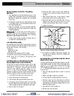
Страница 6: ...30V Available On Request Amps 15 Amps 36 RPM 18 Amps 54 RPM Controls Rotary Type FOR OFF REV Switch ON OFF Foot Switch Pump Gerotor Type Cutter No 820 Roll Type Cut Off Self Centering Full Floating Pipe 1 8 through 2 Bolt 1 4 through 1 or No 821 Blade Type Cut Off Self Centering Full Floating Pipe 1 2 through 2 Dovetail Type Cut Off and Chamfering Tool Reamer No 341 Positive Locking 5 Flute Cone R...

Страница 7: ...rush 3 Inspect the jaw inserts for excessive wear Refer to the Maintenance Instructions if they need to be replaced 4 Make sure the foot switch is present and attached to the Threading Machine Figure 4 Do not operate the Threading Machine without a foot switch 5 Inspect the power cord and plug for damage If the plug has been modified is missing the grounding pin or if the cord is damaged do not us...

Страница 8: ... keep all electrical connections dry and off the ground Do not touch plug with wet hands 9 Check the Threading Machine to insure it is operating properly 6 7 Lubricate the Threading Machine if necessary accord ing to the Maintenance Instructions 8 Use tools and accessories that are designed for your Threading Machine and meet the needs of your application The correct tools and accessories allow yo...

Страница 9: ...ckwise direction as you are facing the front chuck Have the Thread ing Machine serviced if it rotates in the wrong direction or if the foot switch does not control its stopping or starting Depress and hold the foot switch Inspect the mov ing parts for misalignment binding odd noises or any other unusual conditions that may affect the safe and normal operation of the machine If such con ditions are...

Страница 10: ...ening Self Opening or Semi Automatic Die Head 1 Install die set Refer to die installation procedure 2 Swing cutter and reamer to UP position 3 Swing die head to DOWN position with throwout lever set to CLOSE position 4 Check directional switch to insure it is in the FOR Forward position Depress and hold the foot switch down with left foot NOTE Current 535 Machines have an automatic oiling system t...

Страница 11: ...bers face up 2 Flip throwout lever to OPEN position 3 Loosen clamp lever approximately three turns 4 Lift tongue of clamp washer up and out of slot under size bar Slide throwout lever all the way to end of slot in the change die direction indicated on cam plate 5 Remove dies from die head 6 Insert new dies to mark on side of dies Numbers 1 through 4 on the dies must match numbers on the die head 7...

Страница 12: ...Head against the stop As shown 2 Lay the Die Head down flat on a table or bench with the numbers facing up 3 Pull up on the plunger knob and push the handle all the way to the left 4 Select the correct dies for the size desired Size marked on the back end or face of the dies 5 Numbers on the Dies must correspond with those on the Die Head Slots Insert Dies to the line marked on the Dies numbered e...

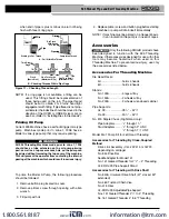
Страница 13: ...asis it is an indication the pump is in need of repair Accessories Only the following RIDGID products have been designed to function with the 535 Threading Machine Other accessories designed for use with other tools may become hazardous when used on this Threading Machine To prevent serious injury use only the accessories listed below Accessories For Threading Machine Die Head Racks 4U holds 4 hea...

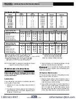
Страница 14: ...ning Operation 811A NPT 1 8 2 1 4 2 Universal Quick R H 815A NPT 1 8 2 1 4 2 Universal Self R H 842 NPT 1 4 2 Universal Quick L H 816 NPT 1 8 3 4 1 4 2 Universal TAP R H 817 NPT 1 2 1 4 2 Universal TAP R H 811A BSPT 1 8 2 1 4 2 Universal Quick R H 815A BSPT 1 8 2 1 4 2 Universal Self R H 531 Bolt 1 4 1 500B Quick R H L H 532 Bolt 11 8 2 500B Quick R H L H Universal Pipe Die NPT NPSM Catalog Number...

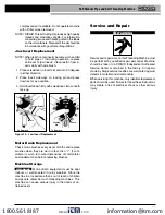
Страница 15: ...eeth on jaw inserts become worn and fail to hold pipe or rod during operation replace entire set of jaw inserts Clean teeth of jaw in serts daily with wire brush 1 Place screwdriver in insert slot and turn 90 degrees in either direction 2 Place insert sideways on locking pin and press down as far as possible 3 Hold insert down firmly with screwdriver turn so teeth face up Figure 13 Jaw Insert Repl...

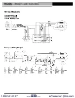
Страница 16: ...A Motor 115V European Wiring Diagram White Blue Black Brown Green Green Yellow 115V 25 60 Hz IEC Standard Black Green White Black Green Yellow Black Suppressor Yellow White Red Blue OFF FWD REV Foot Switch Wiring Diagrams MARRON ROJO BLANCO www com information itm com 1 800 561 8187 ...

Страница 17: ...ts to repair or replace during the warranty period the product is still defective you can elect to receive a full refund of your purchase price What is not covered Failures due to misuse abuse or normal wear and tear are not covered by this warranty RIDGE TOOL shall not be responsible for any incidental or consequential damages How local law relates to the warranty Some states do not allow the exc...

Отзывы: