Ridgid Kollmann SeeSnake KD-125M Скачать руководство пользователя страница 4

4. Do not overreach. Keep proper footing and bal-

ance at all times. Proper footing and balance
enables better control of the tool in unexpected sit-
uations.

5. Use safety equipment. Always wear eye protec-

tion. Dust mask, non-skid safety shoes, hard hat,
or hearing protection must be used for appropriate
conditions.

Tool Use and Care

1. Do not use tool if switch does not turn it ON or

OFF. Any tool that cannot be controlled with the
switch is dangerous and must be repaired.

2. Store idle tools out of the reach of children and

other untrained persons. Tools are dangerous in
the hands of untrained users.

3. Maintain tools with care. Properly maintained

tools are less likely to cause injury.

4. Check for breakage of parts, and any other con-

dition that may affect the tools operation. If dam-
aged, have the tool serviced before using. 
Many
accidents are caused by poorly maintained tools.

5. Use only accessories that are recommended by

the manufacturer for your model. Accessories
that may be suitable for one tool may become haz-
ardous when used on another tool.

6. Inspect tool and extension cords periodically

and replace if damaged. Damaged cords increase
the risk of electrical shock.

7. Keep handles dry and clean; free from oil and

grease. Allows for better control of the tool.

8. Store tools in dry place. Such measures reduce

the risk of electrical shock.

Service

1. Tool service must be performed only by quali-

fied repair personnel. Service or maintenance
performed by unqualified repair personnel could
result in injury.

2. When servicing a tool, use only identical

replacement parts. Follow instructions in the
Maintenance Section of this manual. 
Use of
unauthorized parts or failure to follow maintenance
instructions may create a risk of electrical shock or
injury.

3. Follow instructions for lubricating and chang-

ing accessories. Accidents are caused by poorly

maintained tools.

Specific Safety Information

The Operator’s Manual contains specific safety infor-
mation and instructions for your protection against
serious injuries including:

• Electrical shock or burns from contact with wires

or other electrical parts.

Read and follow the safety labels on machine!

Know the location and functions 

of all controls before using system.

Tool Safety

1. Before using, test the Ground Fault Circuit

Interrupter (GFCI) provided with the power cord
to ensure it is operating correctly. 
GFCI reduces
the risk of electrical shock.

2. Extension cords are not recommended unless

they are plugged into a ground fault circuit inter-
rupter (GFCI) found in circuit boxes or recepta-
cles. 
The GFCI on the monitor power cord will not
prevent electrical shock from the extension cords.

3. Do not operate the system with electrical enclo-

sures removed. Exposure to internal parts
increases the risk of injury.

4. Do not place the monitor and power pack in

water or on a wet surface. Water entering the
housings will increase the risk of electrical shock.

5. Do not use the monitor as a chair or table. Do

not drop or shock the monitor. Can result in
damage to the unit which increases the risk of elec-
trical shock.

SAVE THESE INSTRUCTIONS!

Description, Specifications,
and Standard Equipment

Description

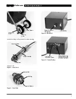
The RIDGID/Kollmann patent pending SeeSnake Pipe
Inspection Tool is ideal for inspecting 2

to 10

drain

lines. Its flexible camera head can negotiate multiple
hard 90° bends, and the fiberglass rod is flexible
enough to easily travel bends, yet stiff enough to push
the camera head over 300

. The hardened stainless

steel camera housing, sapphire crystal lens port (a
material which doesn’t scratch), waterproof connec-

SeeSnake Diagnostic Equipment

Kollmann

3

Содержание SeeSnake KD-125M

Страница 1: ...M KD 200P KD 325M KD 325P IMPORTANT For your own safety before assembling and operating this unit read this Operator s Manual carefully and com pletely Learn the operation applications and potential hazards peculiar to this unit 99 Washington Street Melrose MA 02176 Phone 781 665 1400 Toll Free 1 800 517 8431 Visit us at www TestEquipmentDepot com ...

Страница 2: ... 5 Terms 5 Set Up and Operation To Install the Wheels Onto the Dolly 8 Models with Power Packs 8 Models with Ridgid Kollmann SeeSnake Provided Moniters 9 Hooking Up VCR Systems 9 Prechecks 10 At the Job Site 11 Maintenance Preventative Maintenance 12 Corrective Maintenance 12 Removing the Camera Head 12 Locating Faulted Components 13 Re Installing Camera Head 14 Transportation and Storage 14 Optio...

Страница 3: ...ing parts Replace damaged cords immediately Damaged cords increase the risk of electrical shock 5 When operating a power tool outside use an outdoor extension cord marked W A or W These cords are rated for outdoor use and reduce the risk of electrical shock 6 Connect the tool to an AC power supply that matches the name plate specification Incorrect voltage supply can cause electrical shock or burn...

Страница 4: ...tions may create a risk of electrical shock or injury 3 Follow instructions for lubricating and chang ing accessories Accidents are caused by poorly maintained tools Specific Safety Information The Operator s Manual contains specific safety infor mation and instructions for your protection against serious injuries including Electrical shock or burns from contact with wires or other electrical part...

Страница 5: ...e dolly There are three conductors within this cable that terminate to pins male and sockets female in the connectors See Figure 1 for a detailed description Pins sockets 1 and 2 are the supply and return for the 12 volts DC Pins sockets 3 are the return path for the video signal generated by the camera back to the monitor power pack The connectors on this cable are the same type that are found at...

Страница 6: ...y holds the camera skid in place The skid should be replaced as soon as it wears down to the grooves such that it is smooth Centering Guides Small plastic star shaped devices that mount onto the spring assembly using snap rings 3 and 6 in diameter they center the camera and help keep it off of the bottom out of the sludge Connectors All the plugs in the system that con nect the camera push cable h...

Страница 7: ...ect cable a dimmer and a video out jack providing a signal to your monitor Reel The gray plastic portion of the system that holds the push cable and camera Safety Cables Stainless steel cables two within the spring assembly that connect between the push cable termination and the locking sleeve holding the con nector at the back of the camera head These prevent the spring from over extending when p...

Страница 8: ...ure 5 Camera Spring SeeSnake Diagnostic Equipment Kollmann 7 Wheel Spacer Spring Assembly Camera head Centering Guide Axle Mount 1 of 2 Cotter Pin 1 of 2 Camera Skid LED Ring Sapphire Window Power Button Dimmer to control LED lighting Connector to Interconnect cable Video Out Jack use supplied video cable as input to monitor ...

Страница 9: ...ough the other frame mount 3 Slide the second wheel onto the axle with the flat edge facing outward Slide the washer onto the axle outboard of the wheel then insert the cotter pin at the far end of the axle Models with Power Packs 1 Find the power button at the front of the power pack and make sure it is switched OFF Plug the power pack s power cord into an approved outlet 2 Unwrap the interconnec...

Страница 10: ...n the lower right front of the monitor NOTE These adjustments will be more accurately made when the camera is positioned in a section of pipe If the picture still does not look right or there just isn t one carefully review the above steps to ensure they were properly followed Hooking Up VCR Systems WRONG These types of connec tors commonly referred to as F style and labeled UHF VHF are the incor ...

Страница 11: ...lows you to easily pull cable from the reel yet stops immedi ately when you aren t retrieving cable For trans port add more friction to the brake 3 Grasp the spring assembly in one hand and the camera head in the other Ensure the spring is tightened ONLY to the point where the cut end of it is as far as it can go in the camera head s threads If it is undertightened you should be able to physi call...

Страница 12: ...cable failure and all opera tors should be aware of this If the camera just doesn t seem to want to go any farther DON T FORCE IT If another entry is available try it 7 When inspecting a pipe it is usually necessary to give a little extra push in the bends Back up if nec essary and pop the camera through a turn using the least amount of force required Try to be as gentle as possible and don t hamm...

Страница 13: ...bjects or harsh chemicals be allowed to remain in this area for long periods they may wear on these components Stretch the spring end to end as far as the internal safety cables allow to check this area Stretch again and stir in a bucket of warm water and mild detergent to flush this area Push Cable Reel Dolly 1 The push cable and reel dolly require almost no maintenance Of course a clean system w...

Страница 14: ...reel dolly interconnect cord monitor power pack As a scenario we will assume that the symptom is no video no lights 1 Remove the camera from the spring assembly 2 With the monitor power pack set up for operation plug the camera head directly into the back of the monitor power pack where the interconnect cable is usually connected Turn on the system and check the monitor for a picture If there is a...

Страница 15: ...at ing can damage the imaging chip Options Centering Guides 3 and 6 The centering guides are designed to help center the camera in various sized pipes and also help keep the camera out of the bottom sludge Picture quality is improved as they help position the camera towards the middle of the pipe This allows the camera to see an equal amount of the pipe wall in all directions Do not assume that th...

Страница 16: ... by pushing on it with a sharp object like a screwdriver CAUTION Be sure to use non conductive lubricant a sili cone lubricant is suggested Figure 15 After removing the camera head slip the coil connec tor out of its locking sleeve Some silicone lubricant makes removal much easier Keep the stainless cables untwisted by holding the sleeve and rotating the ring on it that the cables are attached to ...

Страница 17: ...vered by plastic covers This handle greatly improves the stability of the system when rolling particularly for taller operators To install the handle insert the auxiliary handle fittings into their respective mounts on the frame and lock into place using three sets of bolts crown nuts supplied SeeSnake Diagnostic Equipment Kollmann 16 PROBLEM PROBABLE FAULT LOCATION Garbled or jumbled video Lights...

Отзывы: