


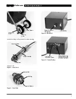


3. On the transmitter, unscrew the plastic locking
sleeve. Place the plastic locking sleeve (leading
with the tapered end) over the coil connector
(Figure 16). Again lubricant makes this easier.
4. Plug the coil cord connector into the rear of the
transmitter, making sure that it is fully seated.
Screw the plastic locking sleeve back onto the
transmitter (Figure 17).
5. Carefully insert the transmitter into the spring
assembly ensuring that no cabling gets bent or
wedged between the transmitter and the spring
assembly. You can stretch the spring assembly,
end-to-end, to help draw the transmitter into it.
6. Push the female connector of the transmitter
through the metal locking sleeve (Figure 18). Use
some silicone lubricant on the exterior of the con-
nector, if necessary.
7. The system should now look like it did when you
first removed the camera head, except the trans-
mitter is within the spring assembly. Re-install the
camera head. (See Re-Installing Camera Head
section.)
8. Refer to the manual provided along with your
receiver for operation of the location equipment.
Auxiliary Handle
The auxiliary handle attaches to the three fittings on
the frame that are covered by plastic covers. This
handle greatly improves the stability of the system
when rolling, particularly for taller operators.
To install the handle, insert the auxiliary handle fittings
into their respective mounts on the frame, and lock into
place using three sets of bolts/crown nuts supplied.
SeeSnake Diagnostic Equipment
Kollmann
16
PROBLEM
PROBABLE FAULT LOCATION
Garbled or jumbled
video
Lights, but no video
No video, no lights
Video, but no lights
White screen
Noisy picture – vertical
stripes on monitor screen
Chart 1 Troubleshooting
Horizontal or Vertical hold need adjustment
75 Ohm-High Z switch in opposite position
Fault within camera, cables , or monitor/power supply
Try to plug back from VCR into monitor with Interconnect cord plugged into monitor
Brightness turned down
Contrast or Brightness improperly set
Break in video carrying conductor (pin/socket #3) between monitor and camera
Fault within camera or monitor/power pack
Monitor/power pack not turned on
Interconnect cable not fully plugged in, or loose connection in system
Fault in any sub-assembly
Dimmer turned down
Fault within camera head, LED section
Camera exposed to excessive light
Contrast/Brightness improperly set
Camera head overheated
Visit us at www.TestEquipmentDepot.com
Test Equipment Depot - 800.517.8431 - 99 Washington Street Melrose, MA 02176 - TestEquipmentDepot.com


