


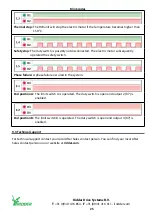


6.2 Status LEDs
The four LEDs D1 (green), D2 (red), D3 (red) and D4 (red) on the control board (A2) give status
indication of the system. This information is important for troubleshooting.
Refer to §9.1 and §9.2. These sections tell about malfunctions and blink codes that can occur.
6.3 Operation
Refer to the “Installation Manual” 265342 and the “User Manual” 265343 of the SynCore system.
Note:
Connection of an external manual control (MC) to the control board of the SynCore RW unit is
NOT permitted.
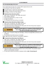
6.4 Fault contacts
The SynCore RW units have a fault contact for feedback. The maximum current for the fault contact
is 0.5 A at 24 V AC/DC.
The fault contact is in operation:
• When the electric motor is thermally stopped
•
When phase failure occurs
•
When the safety switch is operated
• When there is no power supply.
Connect the fault contacts to the input for fault contacts of the PLC
control of the SynCore system.
Ridder Drive Systems B.V.
T
+31 (0)341 416 854 -
F
+31 (0)341 416 611 -
I
20
Содержание SynCore RW Unit
Страница 28: ......


