Ricoh RB5020 Скачать руководство пользователя страница 16

2. Disconnect the top cover at the rear:

[1] Right rear corner ( x1)
[2] Left rear corner ( x1).

3. Disconnect the top cover at the front right corner [1] ( x1)

Common Procedures

15

Содержание RB5020

Страница 1: ...Ring Binder RB5020 Machine Code D737 SERVICE MANUAL V1 1 May 2015 ...

Страница 2: ...d For each step the text description action is followed by the relevant illustration The callouts A B C in text refer to the illustration below not above Added safety caution Never not touch solder connections or electronic parts on the PSU after removing it because electrical charge can remain on the PSU even after it has been removed After removing the PSU never place put it on a conductive mate...

Страница 3: ...ound flathead Black screw heavy fusing unit TCRU Bushing C ring Clip Connector E ring FFC Flat Film Connector FFC Flat Film Connector FFC Flat Film Connector Gear Harness clamp Harness clamp metal fusing unit Hook or tab release sensors Knob screw black Knob screw sliver Pivot screw Screw most common silver Shoulder screw 2 ...

Страница 4: ...apping screw for plastic Timing belt Washer The notations SEF and LEF describe the direction of paper feed The arrows indicate the direction of paper feed In this manual Main Scan means Horizontal and Sub Scan means Vertical both relative to the direction of paper feed 3 ...

Страница 5: ...dous situation Failure to obey a Caution could result in minor or moderate injury or damage to the machine or other property Obey these guidelines to avoid problems such as misfeeds damage to originals loss of valuable data and to prevent damage to the machine This information provides tips and advice about how to best service the machine Safety Label To avoid injury keep the fingers of your other...

Страница 6: ...tc cw Clockwise rotation of a drum roller gear etc BF Booklet Finisher SR5060 D734 1 BW Black and white monochrome copying or printing Bank Paper Bank 1st 2nd 3rd Tray of the main machine CIT Cover Interposer Tray CI5030 D738 1 CIT PB Cover Interposer Tray for Perfect Binder Type S1 D736 2 1 FIN Finisher SR5050 D735 corner staple only no booklets 1 ITB Image Transfer Belt JG Junction Gate LCIT Lar...

Страница 7: ...ertical Transport Unit 1 Optional peripheral devices Trademarks Microsoft and Windows are registered trademarks of Microsoft Corporation in the United States and or other countries PostScript is a registered trademark of Adobe Systems Incorporated PCL is a registered trademark of Hewlett Packard Company Ethernet is a registered trademark of Xerox Corporation PowerPC is a registered trademark of In...

Страница 8: ...Rear Cover 14 Top Cover 14 Removing the Binder Unit 17 Binder Unit Covers 19 Clamp Unit Cover 20 Pre Bind Jogger Left Cover 20 Pre Bind Jogger Bottom Cover 21 Pre Bind Jogger Front Cover 21 Pre Bind Jogger Top Cover 22 Ring Supply Unit Upper Right Cover 23 Ring Supply Unit Right Cover 23 Separating Pre Bind Jogger from Binder Unit 24 Clamp Unit 26 Pre Punch Jog Unit 28 Punch Unit 30 SP6504 Adjustm...

Страница 9: ...it Sensors 50 Ring Cartridge Sensor S801 50 Ring Cartridge Type Sensor S805 51 Rings Reversed Sensor S802 52 50 100 Ring Detection Sensor S804 53 Ring Near End Sensor S803 54 Clamp Unit Sensors 55 Binder Unit HP Sensor S701 55 Bind Timing Sensor S702 56 Ring Switch HP Sensor S706 57 Ring Switch Timing Sensor S707 58 Output Belt Sensors 59 Output Belt 1 HP Sensor S401 59 Output Belt 2 HP Sensor S40...

Страница 10: ...M603 83 Side Fence 1 Motor M604 86 Side Fence 2 Motor M606 88 Spine Clamp Motor M605 91 Runout Roller Motor M609 93 Stack Tamper Motor M607 94 Shutter Motor M608 95 Runout Press Roller Motor M610 97 Fan Motor M611 99 Clamp Unit Motors 99 Clamp Unit Motor M701 99 50 100 Clamp Adjust Motor M702 101 Boards 103 Main Control Board 103 Binder Control Board 103 Removing the Binder Control Board 103 Doing...

Страница 11: ...10 ...

Страница 12: ...y pull the binder unit out of the finisher until it stops There are no wires attached to the binder unit Pushing in the Binder Unit 1 Check the right side of the binder unit and confirm that all the screws are installed and that the binder unit is squarely mounted on its two rails 2 Grip handle Mc8 and slowly push the binder unit into the finisher until it stops 11 ...

Страница 13: ...astic bands 1 to plastic standoffs that are attached to the frame When releasing a harness do not remove the band Use a pair of needle nose pliers to press in the base of the stand off and lift it out of its hole The base of a removed standoff can be quickly re inserted into its hole If you must remove the band Press the end of the band loop Use a sharp tool to press down the lock band below or ab...

Страница 14: ...ge Always remove the ring cartridge before removing the binder unit for servicing 1 Open the right front door 2 Lower the release 1 3 Pull out the ring cartridge 1 and lift it out of the frame Common Procedures 13 ...

Страница 15: ...Rear Cover 1 Remove the rear cover 1 Left rear edge x1 2 Rear cover x7 Top Cover 1 Remove the rear cover 1 Left rear edge x1 2 Rear cover x7 1 Replacement and Adjustment 14 ...

Страница 16: ...2 Disconnect the top cover at the rear 1 Right rear corner x1 2 Left rear corner x1 3 Disconnect the top cover at the front right corner 1 x1 Common Procedures 15 ...

Страница 17: ...4 At the front left corner remove 1 Door plate x3 2 Left door 3 Top cover x3 5 Lift off the top cover 1 1 Replacement and Adjustment 16 ...

Страница 18: ...d slips easily back into the machine and does not provide a stable platform for removing sensors or motors 1 Open the right front door 2 Pull out the binder until it stops 3 Remove 1 Stopper x2 2 Binder unit screws x6 4 Lift the binder unit by its handles 1 and 2 pull it straight up and then slightly to the left to disengage the right side of the unit from the frame and rail The binder unit is hea...

Страница 19: ...5 Hold the binder unit from the rear with a firm grip under the top and bottom of the unit as shown below 6 Lay the binder on its right side with its rubber stoppers down 1 Replacement and Adjustment 18 ...

Страница 20: ...Binder Unit Covers Binder Unit Covers Common Procedures 19 ...

Страница 21: ...oor 2 Remove the ring cartridge 3 Remove the binder unit from its rails and set it on a flat surface page 24 4 Remove the clamp unit cover 1 x2 Pre Bind Jogger Left Cover 1 Open the right front door 2 Remove the ring cartridge 3 Remove the binder unit from its rails and set it on a flat surface page 17 4 Remove the pre bind jogger side cover 1 x4 1 Replacement and Adjustment 20 ...

Страница 22: ...nit from its rails and set it on a flat surface page 17 4 Remove the pre bind jogger bottom cover 1 x4 Pre Bind Jogger Front Cover 1 Open the right front door 2 Remove the ring cartridge 3 Remove the binder unit from its rails and set it on a flat surface page 17 4 Remove lever Mc8 1 x1 Common Procedures 21 ...

Страница 23: ...r 1 x2 Pre Bind Jogger Top Cover 1 Open the right front door 2 Remove the ring cartridge 3 Remove the binder unit from its rails and set it on a flat surface page 17 4 Remove the pre bind jogger top cover 1 x4 1 Replacement and Adjustment 22 ...

Страница 24: ...e 17 4 Lay the binder unit down on its left side stoppers up 5 Remove the right upper cover 1 x2 Ring Supply Unit Right Cover 1 Open the right front door 2 Remove the ring cartridge 3 Remove the binder unit from its rails page 17 4 Lay the binder unit down on its left side stoppers up 5 Remove the right cover 1 x2 Common Procedures 23 ...

Страница 25: ... and remove the ring cartridge 2 Remove the binder unit from its rails and set it on a flat surface page 17 3 Disconnect the binder unit control board 1 x11 x2 4 Remove the pre bind jogger top cover 1 x4 5 Remove handle Mc8 1 x4 6 To separate the pre bind jogger A from the binder unit B remove 1 Front x3 2 Rear x1 1 Replacement and Adjustment 24 ...

Страница 26: ...s 1 of the pre bind jogger off the studs on both sides and lift off binder unit 8 Set the separated pre bind jogger 1 on a clean flat surface 9 If you replace the pre bind jogger do SP 6505 to 6507 Common Procedures 25 ...

Страница 27: ...idge 2 Remove the binder unit from its rails and set it on a flat surface page 17 3 Separate the pre bind jogger from the binder unit page 24 4 Remove the clamp unit cover 1 x2 5 At the lower left corner disconnect the connectors 1 x3 1 Replacement and Adjustment 26 ...

Страница 28: ...6 Disconnect the clamp unit at the bottom 1 Left x2 2 Right x2 7 Remove the clamp unit from the binder unit and lay it on a flat surface Common Procedures 27 ...

Страница 29: ... slightly to the right disconnect the timing belt 2 from the gear 4 Disconnect the motor and sensor 3 x2 5 Open the right front doors 6 Lower plate Mc3 1 so that you can see the side fences 2 7 Push the flaps of the front and rear side fences to the center 8 Remove the screws 3 x2 1 Replacement and Adjustment 28 ...

Страница 30: ...9 At the rear remove the rear screws 1 x2 10 Raise the pre punch jog unit 1 slightly and slowly pull it out of the finisher 11 Set the pre punch jogger unit 1 on a flat surface Common Procedures 29 ...

Страница 31: ...See SP6504 Adjustment in Common Procedures Punch Unit 1 Open the left and right front doors 2 Remove the screws of the punch unit 1 x2 3 Grasp the knob 2 and pull the punch unit out 4 Lay the punch on a flat clean surface 1 Replacement and Adjustment 30 ...

Страница 32: ...ger HP sensor S301 1 The setting for this SP code is written on the white label attached to the plate below the side jogger motor M302 2 Multiply the value by 0 1 For example if the value is 19 then 19 x 0 1 1 9 3 Go into the SP mode execute SP6504 1 A4 LEF or SP6504 2 LT LEF and enter the number Checking the Position of the Punched Holes 1 Close the front door of the Ring Binder Common Procedures...

Страница 33: ...the weight range 70 to 90 g m2 3 With a punched sheet face down as shown below use a micrometer to measure the distances X Y and X1 Standard Values A4 mm LT mm Note X 8 8 12 7 Last hole center to paper edge Y 6 6 Last hole center to paper edge X1 5 625 9 525 Last hole edge to paper edge The distance Y is determined by the size of the punch unit A4 or LT and cannot be adjusted Y is the same distanc...

Страница 34: ... the measured value Z 9 65 from the standard value X1 9 525 and multiply it by 2 9 525 9 65 0 125 x 2 0 250 5 Do SP6504 again and adjust the setting by adding the value derived from the calculation above in this example 0 250 The actual adjustment is done by adjusting the movement of the pre punch jogger fences so that the hole punch position is lowered 0 125 The firmware does this automatically b...

Страница 35: ... jogger unit page 28 3 Set the pre punch jogger unit on a flat surface 4 Turn over the pre punch jogger unit 5 Remove the pre punch jogger HP sensor S301 x1 x1 6 After replacing the pre punch jogger HP sensor S301 do SP6504 See Section 5 of the main service manual 1 Replacement and Adjustment 34 ...

Страница 36: ...he main control board bracket 1 x 27 x8 3 Remove the sensor x1 x1 Pre Bind Jogger Sensors Side Fence 1 HP Sensor S601 1 Open the right front door 2 Remove the binder unit from its rails and set it on a flat surface 3 Remove the pre bind jogger side cover Sensors 35 ...

Страница 37: ...4 Disconnect and move aside the harnesses and clamps x2 x2 5 Remove the screw x1 6 Remove 1 Sensor bracket x1 2 Sensor x3 x1 1 Replacement and Adjustment 36 ...

Страница 38: ...e binder unit from its rails and set it on a flat surface page 17 3 Separate the pre bind jogger from the binder unit page 24 4 Set the pre bind jogger unit on its side with the open end up 5 Remove the screw 1 and sensor bracket x1 6 Remove the sensor x3 x1 Sensors 37 ...

Страница 39: ...ight front door 2 Remove the binder unit from its rails and set it on a flat surface page 17 3 Remove the pre bind jogger left cover page 20 4 Rotate lever Mc7 to lock it 5 Remove sensor bracket 1 x1 x1 1 Replacement and Adjustment 38 ...

Страница 40: ... HP Sensor S604 Alignment Pin Up Sensor S610 1 Open the right front door 2 Remove the binder unit from its rails and set it on a flat surface page 17 3 Remove the pre bind jogger left cover 4 Remove the pre jog binder bottom cover Sensors 39 ...

Страница 41: ...5 Remove 1 x1 2 x2 3 x1 4 x2 5 x3 6 x1 6 Push up the arms of the scissors lift to raise the actuator away from the sensor on the right 1 Replacement and Adjustment 40 ...

Страница 42: ...7 Under the unit base remove the sensor bracket screws x2 8 Remove 1 Alignment pin HP sensor S604 x1 x1 x3 2 Alignment pin up sensor S610 x1 x1 x3 Sensors 41 ...

Страница 43: ...n the right front door 2 Remove the binder unit from its rails and set it on a flat surface 3 Remove the pre bind jogger unit bottom cover 4 Remove the sensor bracket 1 x1 5 Remove the sensor x3 x1 1 Replacement and Adjustment 42 ...

Страница 44: ...the right front door 2 Pull the binder unit out on its rails 3 Rotate lock lever Mc7 so that you can see the screws of the front cover 1 4 Remove the front cover x2 5 Lower lever Mc7 1 to move the actuator 2 away from the sensor Sensors 43 ...

Страница 45: ...he sensor bracket 8 Remove the sensor x3 x1 Stack Thickness Sensor S607 1 Open the right front door 2 Pull the binder unit out on its rails 3 Rotate lock lever Mc7 so that you can see the screws of the front cover 1 1 Replacement and Adjustment 44 ...

Страница 46: ...4 Lower lever Mc7 1 to move the actuator 2 away from the sensor 5 Remove sensor bracket screw 3 x1 6 Remove the sensor bracket Sensors 45 ...

Страница 47: ...ont door 2 Remove the binder unit from its rails and set it on a flat surface page 17 3 Remove the pre bind jogger left cover page 20 4 Remove the pre bind jogger bottom cover page 21 5 Remove the sensor bracket 1 x1 6 Remove the sensor x1 x1 1 Replacement and Adjustment 46 ...

Страница 48: ...Stack Tamper HP Sensor S612 1 Open the right front door 2 Pull the binder unit out on its rails 3 Remove sensor cover 1 x1 Sensors 47 ...

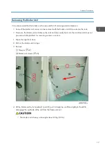
Страница 49: ...4 Remove 1 Spring x1 2 Sensor bracket x2 3 Sensor x1 x1 x3 1 Replacement and Adjustment 48 ...

Страница 50: ...its rails and set it on a flat surface 3 Turn the actuator 1 to the left or right until the cutout is over the sensor 4 Remove the sensor x1 x1 x3 Runout Roller HP Sensor S614 1 Open the right front door 2 Remove the binder unit from its rails and set it on a flat surface Sensors 49 ...

Страница 51: ...r x1 x3 Ring Supply Unit Sensors Ring Cartridge Sensor S801 1 Open the right front door 2 Remove the binder unit from its rails page 17 3 Lay the binder unit on its left side and remove the ring supply unit right cover page 23 4 Remove the sensor bracket 1 x1 x1 1 Replacement and Adjustment 50 ...

Страница 52: ...ridge Type Sensor S805 1 Open the right front door 2 Remove the binder unit from its rails page 23 3 Lay the binder unit on its left side and remove the ring supply unit right cover page 23 4 Remove the sensor bracket 1 x1 x1 Sensors 51 ...

Страница 53: ...sed Sensor S802 1 Open the right front door 2 Remove the binder unit from its rails page 17 3 Lay the binder unit on its left side and remove the ring supply unit right cover page 23 4 Remove sensor bracket 1 x1 1 Replacement and Adjustment 52 ...

Страница 54: ...x1 50 100 Ring Detection Sensor S804 1 Open the right front door 2 Remove the binder unit from its rails page 17 3 Lay the binder unit on its left side and remove the right cover page 23 4 Remove sensor bracket 1 x1 Sensors 53 ...

Страница 55: ...Near End Sensor S803 1 Open the right front door 2 Remove the binder unit from its rails page 17 3 Lay the binder unit on its left side and remove the right cover page 23 4 Remove the sensor bracket 1 x2 1 Replacement and Adjustment 54 ...

Страница 56: ...Clamp Unit Sensors Binder Unit HP Sensor S701 1 Open the right front door 2 Remove the binder unit from its rails and set it on a flat surface page 17 3 Remove the clamp unit cover page 20 4 Remove the sensor bracket 1 x1 Sensors 55 ...

Страница 57: ... sensor x1 x3 Bind Timing Sensor S702 1 Open the right front door 2 Remove the binder unit from its rails and set it on a flat surface page 17 3 Remove the clamp unit cover page 20 4 Remove the sensor bracket 1 x1 1 Replacement and Adjustment 56 ...

Страница 58: ...emove the sensor x1 x3 Ring Switch HP Sensor S706 1 Open the right front door 2 Remove the binder unit from its rails and set it on a flat surface page 17 3 Remove the clamp unit cover page 20 4 Remove the sensor bracket 1 x1 Sensors 57 ...

Страница 59: ...e the sensor x1 x3 Ring Switch Timing Sensor S707 1 Open the right front door 2 Remove the binder unit from its rails and set it on a flat surface page 17 3 Remove the clamp unit cover page 20 4 Remove the sensor bracket 1 x1 1 Replacement and Adjustment 58 ...

Страница 60: ...5 Pull the bracket straight out and turn it over 6 Remove the sensor x1 x3 Output Belt Sensors Output Belt 1 HP Sensor S401 1 Open the right and left front doors 2 Remove base cover 1 x3 Sensors 59 ...

Страница 61: ...3 Raise output tray 1 1 until it stops and remains open 4 Remove the sensor bracket 2 x1 5 Remove the sensor x1 x1 x3 1 Replacement and Adjustment 60 ...

Страница 62: ...Output Belt 2 HP Sensor S402 1 Open the right and left front doors 2 Remove base cover 1 x3 3 Raise output tray 1 1 until it stops and remains open 4 Remove the sensor bracket 2 x1 Sensors 61 ...

Страница 63: ...5 Remove the sensor x1 x1 x3 Output Belt Unit Entrance Sensor S404 1 Open the right and left front doors 2 Remove base cover 1 x3 1 Replacement and Adjustment 62 ...

Страница 64: ...3 Raise output tray 1 1 until it stops and remains open 4 Remove the sensor bracket 2 x1 5 Remove the sensor x1 x1 x1 Sensors 63 ...

Страница 65: ...P Sensor S403 1 Remove the rear cover 2 At the front remove the stacker cover 1 The screw at 2 has a washer Do not lose the washer Be sure to reinstall the screw with the washer at this corner 1 Replacement and Adjustment 64 ...

Страница 66: ...3 Spin the timing belt of the tray lift motor to lower the tray This may take about 1 minute 4 Remove the screws of the panel 1 x4 Sensors 65 ...

Страница 67: ...5 At the back of the finisher remove the panel rear screw x1 6 Remove the panel 7 Remove the sensor bracket 1 x1 1 Replacement and Adjustment 66 ...

Страница 68: ...emove the sensor x1 x1 x1 Stacker Unit Sensors Obstacle Detection Switch S506 1 Remove the rear cover 2 Spin the timing belt of the tray lift motor to lower the tray This may take about 1 minute Sensors 67 ...

Страница 69: ...3 Remove the cover x2 4 Remove the sensor bracket 1 x2 5 Remove the micro switch Standoff x1 x1 x2 1 Replacement and Adjustment 68 ...

Страница 70: ...Book Position Sensor Pair S507E S507R Book Position Sensor S507E 1 Remove panel 1 from the left side of the finisher x4 2 Remove the sensor bracket 1 x1 Sensors 69 ...

Страница 71: ... the sensor x1 x1 Book Position Sensor S507R 1 Remove the rear cover 2 Remove 1 Red connector x1 2 Black connector x1 3 Red black connector x1 4 Lower screws x4 5 Upper screws x4 1 Replacement and Adjustment 70 ...

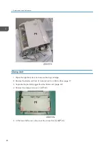
Страница 72: ...3 Remove the sensor bracket x1 4 Remove the sensor x1 x1 Sensors 71 ...

Страница 73: ...Stack Height Sensor Pair S052E S502R Stack Height Sensor S502E 1 Remove panel 1 from the left side of the finisher x4 2 Remove the sensor 1 x1 x1 1 Replacement and Adjustment 72 ...

Страница 74: ...t the front remove the stacker cover 1 The screw at 2 has a washer Do not lose the washer Be sure to reinstall the screw with the washer at this corner 3 Spin the timing belt of the tray lift motor to lower the tray This may take about 1 minute Sensors 73 ...

Страница 75: ...4 Remove the screws of the panel 1 x4 5 At the back of the finisher remove the panel rear screw x1 1 Replacement and Adjustment 74 ...

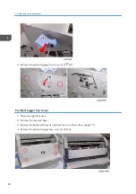
Страница 76: ...6 Remove the panel 7 Remove the sensor bracket 1 x1 8 Remove the sensor x1 x1 x1 Sensors 75 ...

Страница 77: ...Stacker Detect Sensor S504 1 Remove the rear cover 2 Spin the timing belt of the tray lift motor to lower the tray This may take about 1 minute 3 Remove the cover x2 1 Replacement and Adjustment 76 ...

Страница 78: ...4 Remove the sensor bracket 1 x2 5 Remove the sensor x x1 Sensors 77 ...

Страница 79: ...or S505 1 Remove the rear cover 2 Spin the timing belt of the tray lift motor to lower the tray This may take about 1 minute 3 Remove the cover x2 4 Remove the sensor bracket 1 x2 Spring x1 1 Replacement and Adjustment 78 ...

Страница 80: ...5 Remove the sensor x1 x1 Sensors 79 ...

Страница 81: ...Side Jogger Motor M302 1 Remove the rear cover 2 Remove the pre punch jogger unit page 28 3 Set the pre punch jogger unit on a flat surface 4 Turn the pre punch jog unit over 5 Remove the motor x1 x1 x2 1 Replacement and Adjustment 80 ...

Страница 82: ...re Bind Jogger Motors Paddle Roller Motor M601 1 Open the right front door 2 Remove the binder unit from its rails and set it on a flat surface page 17 3 Separate the pre bind jogger unit from the binder unit page 24 4 Turn the pre bind jogger unit onto its left side 5 Disconnect the motor x2 x1 Motors 81 ...

Страница 83: ...nt Pin Motor M602 1 Open the right front door 2 Remove the binder unit from its rails and set it on a flat surface page 17 3 Remove the pre bind jogger left cover page 20 4 Disconnect the motor x2 x1 1 Replacement and Adjustment 82 ...

Страница 84: ...5 Remove the motor bracket and motor x2 6 Remove the motor bracket x2 Paddle Roller Lift Motor M603 1 Open the right front door Motors 83 ...

Страница 85: ...face page 17 3 Separate the pre bind jogger from the binder unit page 24 4 Lay the jogger unit on its left side 5 Disconnect the sensor and open the harness clamps 1 x4 x1 6 Remove the screw and sleeve 2 x1 7 Disconnect both motors x2 1 Replacement and Adjustment 84 ...

Страница 86: ...8 Remove the paddle roller lift assembly 9 Disconnect the motor and bracket 1 and remove them from the paddle roller lift assembly x3 10 Remove the motor from the bracket x2 Motors 85 ...

Страница 87: ...2 Remove the binder unit from its rails and set it on a flat surface page 17 3 Remove the pre bind jogger left cover 4 Below the left corner of the fan 1 loosen Do not remove the screw to release tension on the timing belt 1 Replacement and Adjustment 86 ...

Страница 88: ...5 Disconnect the motor and remove the screws x1 x2 6 Remove the motor 7 Separate the bracket and the motor x2 Motors 87 ...

Страница 89: ...m moving when the motor is re installed 2 Reinstall the motor x1 x2 3 Loosen the tension screw push it to the right to apply tension to the belt then re tighten the screw Side Fence 2 Motor M606 1 Open the right front door 2 Remove the binder unit from its rails and set it on a flat surface page 17 3 Remove the pre bind jogger left cover 1 Replacement and Adjustment 88 ...

Страница 90: ...4 Behind the white gears loosen Do not remove the screw to release tension on the timing belt 5 Disconnect the motor and remove the screws x1 x2 6 Remove the motor Motors 89 ...

Страница 91: ...on 1 Make sure the tension screw 1 is completely to the down then tighten it This provides maximum exposure of the belt 2 below the hole and prevents it from moving when the motor is re installed 2 Reinstall the motor x1 x2 1 Replacement and Adjustment 90 ...

Страница 92: ...lamp Motor M605 1 Open the right front door 2 Remove the binder unit from its rails and set it on a flat surface page 17 3 Remove the pre bind jogger left cover page 20 4 Remove the connectors and harness clamps x2 x6 5 Remove screw 1 x1 6 Remove the motor and bracket 1 to expose the motor 2 Motors 91 ...

Страница 93: ...7 Turn lever Mc7 to expose the front cover 8 Remove the front cover x2 9 Remove the screws 1 and remove the motor bracket 2 x2 10 Separate the bracket and the motor x2 1 Replacement and Adjustment 92 ...

Страница 94: ...m its rails and set it on a flat surface page 17 3 Remove the pre bind jogger left cover page 20 4 Remove the pre bind jogger bottom cover page 21 5 Remove the spine clamp motor M605 6 Disconnect 1 Motor bracket x2 2 Motor x1 x1 7 Remove the motor bracket with the motor 3 Motors 93 ...

Страница 95: ...r x2 Stack Tamper Motor M607 1 Open the right front door 2 Remove the binder unit from its rails and set it on a flat surface page 17 3 Disconnect the motor bracket x2 x1 and x1 4 Remove the motor bracket 1 Replacement and Adjustment 94 ...

Страница 96: ...e the bracket and the motor x2 Shutter Motor M608 1 Open the right front door 2 Remove the binder unit from its rails and set it on a flat surface page 17 3 Disconnect 1 Motor 1 x1 x1 2 Sensor 2 x1 x1 Motors 95 ...

Страница 97: ...the motor bracket x2 5 While holding the motor 1 on the left pull out the spring loaded cam follower 2 then remove the bracket 3 with the motor 6 Separate the bracket and the motor x2 1 Replacement and Adjustment 96 ...

Страница 98: ... 2 Remove the binder unit from its rails and set it on a flat surface page 17 3 Remove the pre bind jogger left cover 4 Disconnect the pin alignment motor 1 and the runout press roller motor 2 x2 x5 x1 5 Disconnect the pin alignment motor bracket x2 Motors 97 ...

Страница 99: ...6 Remove the pin alignment motor 7 Remove the runout press roller motor bracket 8 Remove the timing gear 1 then separate the bracket 2 and the motor x2 1 Replacement and Adjustment 98 ...

Страница 100: ...it 2 Remove the left cover of the pre bind jogger unit page 20 3 Remove the fan motor x1 x2 Clamp Unit Motors Clamp Unit Motor M701 1 Open the right front door 2 Remove the binder unit from its rails and set it on a flat surface page 17 3 Remove the clamp unit Motors 99 ...

Страница 101: ...ds of the brace 6 Pull off the brace 4 to expose the motor 5 7 Mark the shaft and timing gear 1 with a black marker This will make it easier to reattach the gear at reinstallation 8 Remove the e ring 2 and pull off the gear 9 Remove the motor screws 3 1 Replacement and Adjustment 100 ...

Страница 102: ...ont door 2 Remove the binder unit from its rails and set it on a flat surface page 17 3 Remove the clamp unit page 26 4 Release the harnesses 1 x2 x4 5 Remove screws 2 and 3 from the left and right ends of the brace 6 Pull off the brace 4 to expose the motor 5 Motors 101 ...

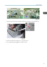
Страница 103: ...7 Disconnect the harnesses and remove the motor x2 1 Replacement and Adjustment 102 ...

Страница 104: ...ee Section 5 of the main Service Manual When adjusting SP6504 close the front door of the Ring Binder After SP6504 adjustment keep the front door of the Ring Binder closed and turn main power switch OFF and ON Binder Control Board Removing the Binder Control Board 1 Open the right front door 2 Remove the binder unit from its rails and set it on a flat surface page 17 Boards 103 ...

Страница 105: ...label attached to the bottom cover of the pre bind jogger unit 2 Enter the SP mode and enter the values on the label Do SP6505 and enter the value of the 1st line 1 Do SP6506 and enter the 1st value of the 2nd line 2 for A4 or the 2nd value for LT Do SP6507 and enter the 1st value of the 3rd line 3 for A4 or the 2nd value for LT 1 Replacement and Adjustment 104 ...

Страница 106: ... 3 Also input the value of SP6504 See Section 5 of the main Service Manual PSU Never not touch solder connections or electronic parts on the PSU after removing it because electrical charge can remain on the PSU even after it has been removed After removing the PSU never place put it on a conductive material such as metal 1 Remove the rear cover 2 Remove the protection plate x2 x1 x8 3 Remove the P...

Страница 107: ...MEMO 106 ...

Страница 108: ...MEMO 107 ...

Страница 109: ...MEMO 108 EN ...

Отзывы: