background image

2.Replacement and Adjustment 

19 

Separation Roller 


Before replacing the separation roller, reset the PM counter. 

1. 

Turn the power ON and enter the SP mode. 

2. 

Execute the following SP corresponding to the part to be replaced to reset the PM counter. 

- SP7-804-052 (Rset PM Counter: Spr. Bank1) 

- SP7-804-054 (Rset PM Counter: Spr. Bank2) 

- SP7-804-056 (Rset PM Counter: Spr. Bank3) 

3. 

Turn the power OFF. 


1. 

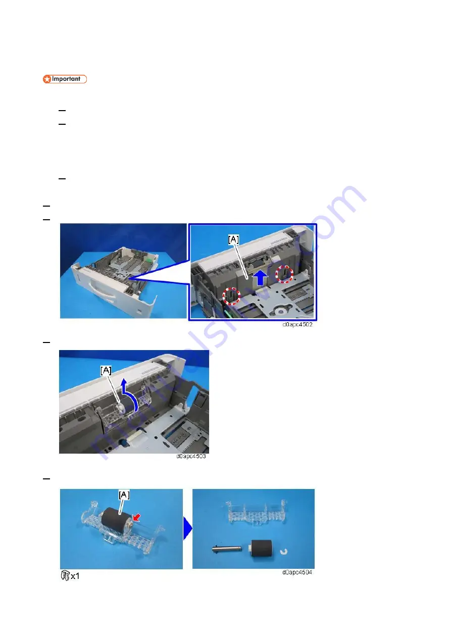
Remove the paper cassette. 

2. 

Remove the inner cover [A] while pressing the two lock buttons in the paper tray. 


3. 

Raise the holder of the separation roller [A] and remove it. 


4. 

Remove the separation roller [A] from the holder. 


Содержание PB1110

Страница 1: ...Paper Feed Unit PB1120 PB1110 Machine Code D3ER D3EQ Field Service Manual Ver 1 0 Initial Release February 2019 c 2019 Ricoh Co Ltd ...

Страница 2: ......

Страница 3: ...Symbols and Abbreviations This manual uses several symbols Symbol What it means Screw Connector Clip ring Clamp SEF Short Edge Feed LEF Long Edge Feed A Short Edge Feed SEF B Long Edge Feed LEF ...

Страница 4: ......

Страница 5: ... Adjustment in the Optional Paper Tray 7 2 Replacement and Adjustment 8 Right Cover 8 Controller Board PCB1 10 Bank Drive Motor M1 11 Bank Cooling Fan FAN1 12 Paper Size Switch SW1 13 Paper Feed Clutch CL1 Paper Transport Clutch CL2 14 Paper End Sensor S1 16 Paper Near end Sensor S2 Paper Transport Sensor S3 17 Paper Feed Roller 18 Separation Roller 19 ...

Страница 6: ...Item 1 Controller board PCB1 7 Paper end sensor S1 2 Bank cooling fan FAN1 8 Paper transport roller 3 Bank drive motor M1 9 Friction roller 4 Paper transport clutch CL2 10 Paper transport sensor S3 5 Paper feed clutch CL1 11 Paper feed roller 6 Paper size switch SW1 12 Paper near end sensor S2 ...

Страница 7: ... C and starts rotating the paper transport roller D which feeds the paper When the leading edge of the moving paper switches on the registration sensor this switches the paper feed clutch CL1 and paper transport clutch CL2 off Image position timing starts while the registration sensor is on and then the paper is transported to the transfer unit The paper feed clutch CL1 and paper transport clutch ...

Страница 8: ... plate lock lever A and releases it When the lock is released a spring raises the bottom plate B and paper stack to the feed roller Also the bottom plate and end fence are linked so when the bottom tray rises the end fence shifts forward against the trailing edge of the stack This keeps the edge of the stack against the fence to prevent misfeeds ...

Страница 9: ... feed out the bottom plate rises This also raises the feeler of the paper near end sensor S2 D until it blocks the gap of the sensor and switches it off Paper near end is detected when there are about 75 50 sheets of paper 0 1 mm thick remaining in the tray When paper near end is detected the operation panel displays the paper near end message If paper end is detected before paper near end paper e...

Страница 10: ...escriptions 6 Value SW 1 SW 2 SW 3 Paper size 1 L L L A4 SEF 2 L H L A5 SEF 3 H L L A6 SEF 4 H H L Legal SEF 5 L L H Letter SEF 6 L H H 7 H L H Half letter SEF 8 H H H Paper cassette is not set L Switch is pressed ...

Страница 11: ... To adjust side to side registration loosen the two screws on the underside of the tray and move the rack and pinion mechanism of the side guides from side to side The holder A can move to right or left up to 2mm When at the default 0 position the holder position is the triangle marked area ...

Страница 12: ...ain machine mounted on the paper feed unit 1 Remove the paper cassette 2 Remove the right cover A Paper Feed Unit PB1110 250 sheets Disconnect the boss and then open the right cover by holding the bottom part of it to release two hooks Paper Feed Unit PB1120 500 sheets 1 Disconnect the two bosses and then open the right cover by holding the upper side of the right cover to release two upper hooks ...

Страница 13: ...2 Replacement and Adjustment 9 ...

Страница 14: ...2 Replacement and Adjustment 10 Controller Board PCB1 1 Remove the right cover Right Cover 2 Remove the controller board PCB1 A ...

Страница 15: ...2 Replacement and Adjustment 11 Bank Drive Motor M1 1 Remove the right cover Right Cover 2 Remove the bank drive motor M1 A ...

Страница 16: ...2 Replacement and Adjustment 12 Bank Cooling Fan FAN1 1 Remove the right cover Right Cover 2 Remove the bank cooling fan FAN1 A with the bracket 3 Remove the bank cooling fan FAN1 A from the bracket ...

Страница 17: ...Paper Size Switch SW1 1 Remove the right cover Right Cover 2 Remove the paper size switch SW1 A with its bracket 3 Deattach the paper size switch SW1 A from the bracket 4 Release the two hooks to to remove the paper size switch SW1 A ...

Страница 18: ...ze switch SW1 Paper Size Switch SW1 3 Release the clip to remove the bearing B and then remove the bracket A 4 Remove the paper feed clutch CL1 A 5 Remove the bearing A and flange B to remove the paper transport clutch CL2 C When attaching the bracket removed in Step 3 make sure that the clutch connectors are seated correctly on the holder ...

Страница 19: ...2 Replacement and Adjustment 15 ...

Страница 20: ...2 Replacement and Adjustment 16 Paper End Sensor S1 1 Remove the main machine from the paper feed unit 2 Remove the paper cassette 3 Remove the top cover A 4 Remove the paper end sensor S1 A ...

Страница 21: ...nd Sensor S2 Paper Transport Sensor S3 1 Remove the main machine from the paper feed unit 2 Remove the paper cassette 3 Remove the top cover A 4 Remove the bracket A 5 Remove the paper near end sensor S2 B 6 Remove the paper transport sensor S3 C ...

Страница 22: ...SP mode 2 Execute the following SP corresponding to the part to be replaced to reset the PM counter SP7 804 051 Rset PM Counter Feed Bank1 SP7 804 053 Rset PM Counter Feed Bank2 SP7 804 055 Rset PM Counter Feed Bank3 3 Turn the power OFF 1 Remove the paper cassette 2 Slide the lever A to the left as shown below to remove the paper feed roller B ...

Страница 23: ...he part to be replaced to reset the PM counter SP7 804 052 Rset PM Counter Spr Bank1 SP7 804 054 Rset PM Counter Spr Bank2 SP7 804 056 Rset PM Counter Spr Bank3 3 Turn the power OFF 1 Remove the paper cassette 2 Remove the inner cover A while pressing the two lock buttons in the paper tray 3 Raise the holder of the separation roller A and remove it 4 Remove the separation roller A from the holder ...

Отзывы: