background image

1

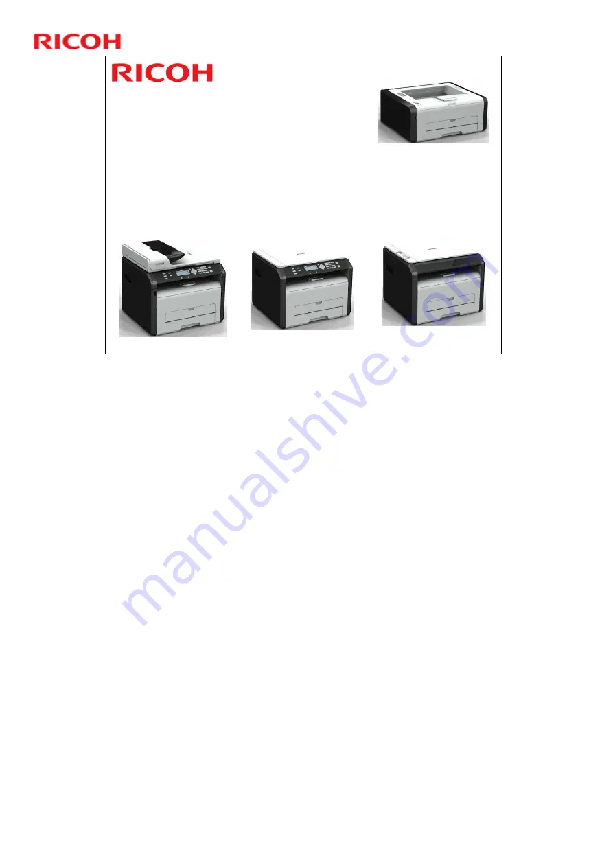
OP-P1/MF1 Training

Slide 1

Model OP-P1 

(M133/M144/M145/M146/M162/M163/M164)

Model OP-MF1 

(M134/M135/M141/M142/M143/M147/M148/M149/M150/M151/

M165/M166/M167/M168/M169/M191)

Service Training

Version 1.1

These models are for the following regions

M133, M134, M135, M141, M142, M143, M144, M191: China

M162: India

M164, M169: Asia

M163, M165, M166, M167, M168: India and South America

M145, M146, M147, M148, M149, M150, M151: Europe and North America

TTP version information

Version 1.0: China only (M133, M134, M135, M141)

Version 1.1: Worldwide models introduced. The following slides were modified 
(slide numbers are the numbers used in version 1.0)

Changes related to the increased number of models: Slides 1, 5, 6, 7, 8, 9, 
14, 18 (one line deleted), 21, 22, 26, 27, 29, 30, 31, 35, 38, 39, 41, 43, 48 to 
58, 75, 108, 109; also, a slide was inserted after slide 6

AIO refill is not for EU/NA models: Slides 4, 12, 13, 70, 81, 83

Tray cover, Scan to USB, handset: Slides 7 to 9

Front door switch: Slides 25, 67

Changes to external component and operation panel diagrams (these are 
now slides 8 to 16)

Other changes: Slides 13, 14, 105, 119

Version 1.2: Wireless LAN models and M191 for China introduced. The following 
slides were modified (slide numbers are the numbers used in version 1.1)

Changes related to the increased number of models: Slides 1, 4, 5, 6, 7, 8, 
10, 17, 18, 75, 80, 86

Minor change to diagram (model code numbers such as M133 are now
obscured): Slides 34, 35, and 36

Содержание OP-MF1

Страница 1: ...s used in version 1 0 Changes related to the increased number of models Slides 1 5 6 7 8 9 14 18 one line deleted 21 22 26 27 29 30 31 35 38 39 41 43 48 to 58 75 108 109 also a slide was inserted after slide 6 AIO refill is not for EU NA models Slides 4 12 13 70 81 83 Tray cover Scan to USB handset Slides 7 to 9 Front door switch Slides 25 67 Changes to external component and operation panel diagr...

Страница 2: ...uirements Modify as necessary depending on your situation Preparation Prior to starting this course prepare the following items Training machines in the shipping boxes A set of service tools Field Service Manual User s Manuals Requirements for trainees Prior to starting this course the following training or equivalent should be completed Fax basics course Copier basics course The trainee should al...

Страница 3: ...3 OP P1 MF1 Training Slide 3 Model OP P1 MF1 Service Training 1 Product Outline No additional notes ...

Страница 4: ...s done by the customers All models except the Europe and North America models M145 M146 M147 M148 M149 M150 and M151 Customers can refill the AIO with toner and the used toner can be discarded After refilling the toner 3 times the photo conductor is getting old so the customer must replace the AIO this is the only PM replacement item GDI driver with support for Windows only No additional notes ...

Страница 5: ...EDs The top of the machine is covered by a plastic maintenance cover Use Smart Organizing Monitor to make machine settings monitor the error codes and execute other functions OP P1a M133 M162 OP P1an M144 M145 M163 OP P1aw M146 M164 The OP P1 has only a printer function It doesn t have a full operation panel but has 2 keys and 2 LEDs The top of the machine is covered by a plastic maintenance cover...

Страница 6: ...ith more buttons and a 2 digit display The top of the machine is covered by a platen cover and flatbed scanner unit except for the M148 M166 and M191 which have an ADF instead of a platen cover The M148 M166 and M191 also have a larger operation panel almost the same as the 4 in 1 model but without the fax functions Use Smart Organizing Monitor to make machine settings monitor the error codes and ...

Страница 7: ...ion panel with a full array of keys a 10 key pad and a 7 digit display The top of the machine is covered by a ADF and a flatbed scanner unit except for the M141 which has a platen cover instead of an ADF M149 M150 M151 Europe N America models In these models the AIO cannot be refilled with toner Use Smart Organizing Monitor to make machine settings monitor the error codes and execute other functio...

Страница 8: ...over 7 Bypass tray 12 USB port 5 Output tray 11 Rear cover 4 Alert indicator 10 Power connector 3 Power indicator 9 Power switch 2 Start key 8 Tray 1 1 Job Reset key See the User s Guide for detailed external component descriptions Tray cover The North America model has two types LT and LG Other versions have only one type A4 LT ...

Страница 9: ...ray 1 11 USB port Scan to USB not available in China 4 Output tray 10 Rear cover 3 Exposure glass cover 9 Power connector 2 Operation panel 8 Power switch 1 Exposure glass See the User s Guide for detailed external component descriptions Tray cover The North America model has two types LT and LG Other versions have only one type A4 LT ...

Страница 10: ... Power switch 1 Exposure glass See the User s Guide for detailed external component descriptions Tray cover The North America model has two types LT and LG Other versions have only one type A4 LT In the M141 the Auto Document Feeder ADF has not been installed Line and TEL Connector M135 M141 M143 M149 M150 M151 M167 M168 and M169 For M135 M141 M143 Upper port Port for handset connection Middle por...

Страница 11: ...11 OP P1 MF1 Training Slide 11 Operation Panel Printer Chinese Version 4 Alert indicator 2 Start key 3 Power indicator 1 Job Reset key See the User s Guide for detailed operation panel descriptions ...

Страница 12: ...2 OP P1 MF1 Training Slide 12 Operation Panel Printer International Version 4 Alert indicator 2 Start key 3 Power indicator 1 Job Reset key See the User s Guide for detailed operation panel descriptions ...

Страница 13: ...in 1 Chinese Version 10 Alert indicator 5 Display LCD 9 Power indicator 4 ID Copy key 8 Start key 3 Density key 7 Stop Cancel key 2 Density indicator 6 Copy Number key 1 Document Type key See the User s Guide for detailed operation panel descriptions ...

Страница 14: ...cator 4 ID Copy key 8 Start key 3 Density key 7 Stop Clear key 2 Density indicator 6 Copy Number key 1 Document Type key Note that for the models with ADF M148 M166 the operation panel is the same as the 4 in 1 model but without the keys for the fax functions See the User s Guide for detailed operation panel descriptions ...

Страница 15: ...ower indicator 2 Copy key 7 Stop Clear key 13 Number keys 6 OK key 12 Scroll keys 5 User Tools key 11 Alert indicator 4 ID card copy On hook key 10 Display screen 3 Speed dial key 8 Start key Fax tx rx 1 Fax key See the User s Guide for detailed operation panel descriptions ...

Страница 16: ...er key 2 Copy key 14 Number keys 7 Stop Clear key 13 Scroll keys 6 OK key 12 Alert indicator 5 User Tools key 11 Display screen 4 ID card copy On hook key 10 Power indicator 3 Speed dial key 8 Start key Fax tx rx 1 Fax key See the User s Guide for detailed operation panel descriptions ...

Страница 17: ...get Users Business personal and small office Can double as a small office printer copier fax Technical Enhancements compared to some competitors predecessors Compact Small footprint Genuine refill toner all models except the Europe and N America models M145 M146 M147 M148 M149 M150 and M151 Fast first print No additional notes ...

Страница 18: ...About 1500 pages except for the China models M133 M134 M135 M141 M142 M143 M144 M191 Yield values are for when printing on A4 or 8 x 11 paper 5 chart in accordance with ISO IEC 19752 All models except the Europe and N America models M145 M146 M147 M148 M149 M150 and M151 Refill toner is also available Each AIO can be refilled up to 3 times No additional notes ...

Страница 19: ...int Volume OP P1a 400 prints month OP MF1a 500 prints month OP P1a OP MF1a China models 800 prints per month MPBF OP P1a 26k prints OP MF1a 22k prints Expected product life All models 5 years or 60 000 prints whichever comes first ME MF1 P1 Expected life was 50k ...

Страница 20: ...20 OP P1 MF1 Training Slide 20 Model OP P1 MF1 Service Training 2 Specifications No additional notes ...

Страница 21: ...a is received until paper exits First copy time Less than 25 s ADF platen Resolution Printing Copying 600 x 600 dpi 1200 x 600 dpi Scan from exposure glass 600 x 600 dpi 600 x 300 dpi Scan from ADF 600 x 300 dpi ADF capacity 15 sheets Input tray capacity 150 sheets Bypass tray 1 sheet Output tray capacity 50 sheets Duplex printing Manual This slide shows the basic specifications For more detailed ...

Страница 22: ...er Half letter B5 ISO A5 B6 A6 Executive 16K Legal Bypass Tray Width 100 mm to 216 mm 3 5 to 8 5 Length 148 mm to 356 mm 5 8 to 14 ADF Width 105 to 216 mm 4 1 to 8 5 Length 127 to 356 mm 5 to 14 Media type ADF standard and bypass trays Plain Paper Recycled Paper Paper weight Standard Tray 60 105g m2 16 28lb No additional notes ...

Страница 23: ... OP MF1afh OP MF1afhu 32 MB No upgrades available Hard disk None Not available as standard or as option Fax Compression Methods MH MR MMR Modem Speed 33 6kbps 2400bps Transmission Speed Approx 3 s page Power Consumption Copying 350W or less Standby 55W or less Sleep 5W or less No additional notes ...

Страница 24: ...24 OP P1 MF1 Training Slide 24 Model OP P1 MF1 Service Training 3 Installation No additional notes ...

Страница 25: ...all the machine when you are in the field The full installation procedure is in the Quick Installation Guide Before you start installation Check the accessories Confirm the location to install the machine space power source environment The space requirements depend on the model see the next slide Recommended office environment range No additional notes ...

Страница 26: ...26 OP P1 MF1 Training Slide 26 Space Requirements Printer model With platen cover With ADF No additional notes ...

Страница 27: ...ridge shake it 5 or 6 times and reinstall it Connect the power cord and USB cord Install the printer software in the computer Load paper in the paper tray and open the output tray 4 in 1 models only Connect the phone line Set up the fax functions The User s Guide contains more information about machine setup options Familiarize yourself with it in case the user requests your help No additional not...

Страница 28: ...28 OP P1 MF1 Training Slide 28 Model OP P1 MF1 Service Training 4 Machine Overview No additional notes ...

Страница 29: ...29 Component Layout 1 Exit Rollers 2 Straight Rollers 3 Exit Sensor 4 Hot Roller 5 Pressure Roller 6 Drum 7 Transfer Roller 8 Registration Sensor 9 Paper 10 Feed Roller 11 Manual Feed Tray 12 Connecting Roller No additional notes ...

Страница 30: ...rd 4 Interlock Switch Fusing Unit Cover 5 Main Switch 6 PSU 7 HVPP High Voltage Power Pack 8 Paper End Sensor 9 Registration Sensor 10 By pass Set Sensor 11 Paper Feed Clutch 12 Main Motor 13 Paper Exit Sensor 8 9 10 11 12 13 Front door switch North America models have two switches Models for other regions have one ...

Страница 31: ...rmistor End 22 Fax Board 4 in 1 models 23 Speaker 4 in 1 models 14 15 16 17 18 19 20 21 22 23 16 Thermistor This thermistor is above the laser unit It detects the temperature inside the machine If it becomes higher than 52 degrees C printing stops Then when it falls below 50 degrees C again printing will restart This operation is necessary because of the lack of cooling fans in this machine ...

Страница 32: ...ical Component Layout 3 24 Scanner Motor 25 ADF Motor 26 ADF Sensor 1 27 ADF Sensor 2 28 CIS 29 Operation Panel Unit Items 24 to 28 3 in 1 and 4 in 1 models only Items 25 to 27 Only in models with ADF 24 25 26 27 28 29 No additional notes ...

Страница 33: ... a gear train 2 drive the feed roller 3 and transport roller 4 the drum 5 inside the AIO the hot roller 6 the fusing exit roller 7 and the exit roller 8 The paper feed clutch 9 engages and disengages the rotation of the feed roller during paper feed No additional notes ...

Страница 34: ...del Panel Key LED Front Door Swich I L Thermistor Fusing Thermistor Center Main Motor Main Motor Paper Exit Sensor Fusing Thermistor End By pass Set Sensor Registration Sensor Paper End Sensor Rear Cover Switch I L LDB Laser diode board I L SW Interlock switch ...

Страница 35: ...LED Scanner CIS Motor Front Door Swich I L Thermistor Fusing Thermistor Center Main Motor Polygon Mirror Motor Paper Exit Sensor Fusing Thermistor End By pass Set Sensor Registration Sensor Paper End Sensor Rear Cover Switch I L LDB Laser diode board I L SW Interlock switch ...

Страница 36: ...r Front Door Switch I L Thermistor Fusing Thermistor Center Main Motor Polygon Mirror Motor Paper Exit Sensor Fusing Thermistor End By pass Set Sensor Registration Sensor Paper End Sensor Rear Cover Switch I L Fax ADF ADF Sensor 1 ADF Sensor 2 Motor LDB Laser diode board I L SW Interlock switch ...

Страница 37: ...37 OP P1 MF1 Training Slide 37 ADF Paper Path The solid red line shows the path that documents take through the ADF No additional notes ...

Страница 38: ...r takes through the machine 1 Paper Exit Sensor 2 Fusing Exit Roller 3 Exit Roller 4 Hot Roller 5 Pressure Roller 6 Drum 7 Transfer Roller 8 Registration Sensor 9 Paper 10 Feed Roller 11 By pass Set Sensor 12 Paper End Sensor The registration sensor sets registration timing Laser on timing ...

Страница 39: ...aper Before loading paper the paper size and paper type must be selected on the initial screen System Settings of the Smart Organizing Monitor Also in print mode the user must select the correct size on the printer driver No additional notes ...

Страница 40: ...odels have a 2 line display that can show SC codes and messages The display for the 3 in 1 models is limited to two digits The printer model has no display The Service Mode of Smart Organizing Monitor can be used to view error messages for all machines No additional notes ...

Страница 41: ...41 OP P1 MF1 Training Slide 41 Model OP P1 MF1 Service Training 5 Maintenance Maintenance Service mode Cleaning No additional notes ...

Страница 42: ...hine is designed for user maintenance so it does not have a periodic maintenance schedule Refer to the maintenance information in the User Guide Operating Instructions User Guide Maintaining the Machine Also see the Using the Service Mode slide No additional notes ...

Страница 43: ...m the control panel User Guide Configuring the Machine Using the Control Panel All models can be configured set up using the Smart Organizing Monitor User Guide Configuring the Machine Using the Smart Organizing Monitor Refer to User Maintenance Mode in the FSM for details about user access procedures ...

Страница 44: ...g Utilities Smart Organizing Monitor Service Mode Yes Yes Yes Error history 5 Yes Yes Yes Counter information 4 Yes Yes Yes See the next slide Engine maintenance 3 No No Yes Power ON Fax key Fax test 2 No No Yes From Ready state Stop Reset 1 0 7 Start Fax maintenance 1 Printer 3 in 1 4 in 1 To Enter Service Mode Function No Note The Service Mode of the Smart Organizing Monitor is your best tool fo...

Страница 45: ...e Service Mode To open the Service Mode Step 1 Click About Step 2 Press Ctrl Shift and double click the right mouse button in the image area of the Smart Organizing Monitor Orange outlined area above About button Image area No additional notes ...

Страница 46: ...ep mode automatically during the firmware update The firmware update may take a while to complete so you may need to switch off the standby or sleep mode settings in the PC operating system 4 in 1 models Unplug the fax cable before starting the update Make sure that the machine is on and connected to the PC by its USB cable Before you start print the Configuration page using Smart Organization Mon...

Страница 47: ...splays during the update and after the update has finished The manual also explains what happens if the firmware update fails Do not cut the power unplug the USB cable or do any other operation during the update After the update has finished Cycle the main power off on to initialize the firmware Print another Configuration Page and check it to make sure that the firmware was updated Service Manual...

Страница 48: ...Engine firmware update If the firmware update fails SC871 appears 3 in 1 models show c7 and in the printer version only the Alert LED lights The main board must be replaced Controller firmware update If the firmware update fails try again No additional notes ...

Страница 49: ... maintenance measure you may need to clean machine components during service calls Go to the machine and practice the cleaning procedures Refer to the User Guide for the cleaning procedures Pay particular attention to the Cautions when Cleaning section Never use an organic solvent like benzene thinner acetone etc to clean the machine No additional notes ...

Страница 50: ...ount up is done at the time of image writing So in this machine count up is done even when jam detection occurs after writing This process differs from existing machines where count up is done after feeding out the printed paper No additional notes ...

Страница 51: ...51 OP P1 MF1 Training Slide 51 Model OP P1 MF1 Service Training 6 Detailed Section Descriptions No additional notes ...

Страница 52: ...52 OP P1 MF1 Training Slide 52 Model OP P1 MF1 Service Training Detailed Section Descriptions Scanning No additional notes ...

Страница 53: ... for continuous scanning Originals can also be scanned from the exposure glass one at a time book mode 1 Original Feed Tray 2 Pick up Roller 3 ADF Sensor 1 4 ADF Roller 5 ADF Sensor 2 6 Feed Roller 7 Scanning Glass ADF originals 8 CIS 9 Original Exit Roller 10 Original Output Tray ...

Страница 54: ...to the ADF after the operator pushes Start on the operation panel The ADF scanner motor will not turn on and rotate the entrance roller unless ADF sensor 1 3 detects a sheet of paper ready to be fed 1 Original Feed Tray 2 Pick up Roller 3 ADF Sensor 1 4 ADF Roller 5 ADF Sensor 2 6 Feed Roller 7 Scanning Glass ADF originals 8 CIS 9 Original Exit Roller 10 Original Output Tray ...

Страница 55: ...nal as passes and continues to feed past the feed roller 6 If the leading and trailing edges of the paper do not pass ADF sensor 2 within the time prescribed for the paper length this will trigger a jam 1 Original Feed Tray 2 Pick up Roller 3 ADF Sensor 1 4 ADF Roller 5 ADF Sensor 2 6 Feed Roller 7 Scanning Glass ADF originals 8 CIS 9 Original Exit Roller 10 Original Output Tray ...

Страница 56: ...below the ADF scanning glass scans the original as it passes overhead The exit roller 9 feeds to original out of the ADF and onto the original output tray 10 1 Original Feed Tray 2 Pick up Roller 3 ADF Sensor 1 4 ADF Roller 5 ADF Sensor 2 6 Feed Roller 7 Scanning Glass ADF originals 8 CIS 9 Original Exit Roller 10 Original Output Tray ...

Страница 57: ... MF1 Training Slide 57 ADF Operation 4 In ADF mode the CIS stays below the ADF scanning glass during scanning CIS Original Original Feed Direction ADF Scanning Glass The CIS is shaded in yellow in this diagram ...

Страница 58: ... exposure glass the CIS is moved from left to right by a timing belt The timing belt does not move when scanning originals from the ADF The CIS remains stationary on the left under the ADF scanning glass Original CIS Movement Direction CIS ADF Scanning Glass The CIS is shaded in yellow in this diagram ...

Страница 59: ...ng Slide 59 ADF Components The ADF A is mounted on top of the flatbed scanner B 1 Operation Panel 2 ADF Motor 3 Original Set Sensor ADF Sensor 1 4 Original Feed Sensor ADF Sensor 2 5 CIS Unit 6 Timing Belt 7 Scanner Motor ...

Страница 60: ...60 OP P1 MF1 Training Slide 60 Flatbed Scanner Components The CIS and flatbed scanner motor are the only two electrical components in the flatbed scanner 1 CIS 2 CIS Cradle 3 Timing Belt 4 Scanner Motor ...

Страница 61: ...61 OP P1 MF1 Training Slide 61 Flatbed Hinge Mechanism 1 1 Flatbed Scanner Unit Base 2 Support Arm 3 Guides 4 Spring No additional notes ...

Страница 62: ...of the left cover and connected to the bottom of the flatbed unit The hinge locks and holds when the top of the machine is raised On machines with scanner and no ADF the flatbed unit is raised On machines with scanner and ADF the ADF and flatbed unit are raised together No additional notes ...

Страница 63: ...the left The top of the hinge is connected to the base of the flatbed scanner 1 The end convex part 3 of the support arm 2 is joined to the guide 4 The end moves within this guide when the flatbed is lifted or lowered The mechanism lies flat in the locked position 5 No additional notes ...

Страница 64: ...64 OP P1 MF1 Training Slide 64 Replacement of Parts The only serviceable part in the ADF is the original tray cover If other part malfunctions occur replace the whole ADF No additional notes ...

Страница 65: ...65 OP P1 MF1 Training Slide 65 Model OP P1 MF1 Service Training Detailed Section Descriptions Laser Unit No additional notes ...

Страница 66: ...66 OP P1 MF1 Training Slide 66 Top View Cover On 1 Top Cover 2 Laser Decal 3 LD Board No additional notes ...

Страница 67: ...r 6 Laser Synchronization Detector 7 F theta Lens 8 1st Mirror 9 Shield Glass 10 Thermistor The thermistor 10 monitors the temperature in the machine and the print job stops when it is more than 52 degrees Celsius to let the machine cool down The machine resumes automatically when the temperature goes down to 50 degrees Celsius ...

Страница 68: ...e 3 and cylindrical lens 4 The aperture and cylindrical lens focus the beam and aim it at the polygon mirror The polygon mirror 5 rotates clockwise at a very high but constant speed When the laser beam strikes a face of the mirror the mirror surface reflects the beam across the photoconductor surface of the drum after passing through more lenses and mirrors No additional notes ...

Страница 69: ...o the drum Laser synchronization done by the laser synchronization detector 6 Main scan start position Main scan intermediate position between the start and end points Main scan end position Each step is repeated for each beam reflected from each face of the polygon mirror The laser synchronization detector 6 controls the timing of the laser operation No additional notes ...

Страница 70: ...nto the photoconductive surface of the drum The angles between the beams that form the image elements are equal However if the beams are projected without adjustment the diameters of each element projected onto the drum surface may be different wide at the ends and narrow at the center The F theta lens corrects each beam so that it is projected onto the drum surface at a constant speed and deflect...

Страница 71: ...e polygon mirror 1 reflects the laser beam through the F theta lens 2 The first mirrors 3 deflect the beam through the shield glass 4 on the front bottom edge of the laser unit and onto the photoconductor surface of the drum below the laser unit No additional notes ...

Страница 72: ...over is opened or closed North America models have two switches Models for other regions have one Interlock switch fusing unit cover Turned on off by the straight guide plate which is pushed by the arm When the cover opens power supply to the laser unit is cut to secure safety during maintenance and jammed paper removal A Arm B Straight Guide Plate C Left Side Plate D Interlock SW Fusing Unit Cove...

Страница 73: ...age and check the position of the image area on the page as explained in the replacement procedure in the service manual There are no SP adjustments There are no serviceable parts inside the laser unit Never attempt to disassemble the laser unit and then reinstall it in the machine No additional notes ...

Страница 74: ...74 OP P1 MF1 Training Slide 74 Model OP P1 MF1 Service Training Detailed Section Descriptions Image Creation No additional notes ...

Страница 75: ...e refilled All models except the the Europe and N America models M145 M146 M147 M148 M149 M150 and M151 An AIO can be refilled up to three times this is the approximate service life of the drum The refillings greatly extend the service life of the AIO The AIO can be easily removed and replaced by the user The AIO has an ID chip which helps the machine to detect when an AIO is set and when a new AI...

Страница 76: ...it 1 Waste Toner Tank 2 Development Roller 3 Toner Hopper 4 ID Chip 5 Agitator 6 Agitator Feeler 7 Toner Supply Roller 8 Transfer Roller 9 Drum 10 Charge Roller 11 Cleaning Blade The print cartridge is called the AIO all in one throughout this course ...

Страница 77: ... charge to the photoconductive surface of the drum 2 A developer toner mixture from the toner supply unit 4 is picked up by the toner supply roller 5 and applied to the development roller 6 The areas of the latent image on the drum created by exposure to the laser beam pick up toner from the development roller No additional notes ...

Страница 78: ...er roller pulls the toner off the drum onto the paper to form the image The cleaning blade 9 removes unused toner from the surface of the drum The toner removed from the drum by the cleaning blade is collected in the waste toner unit 10 The paper passes out between the drum and transfer roller and goes to the fusing unit No additional notes ...

Страница 79: ...act Points with Main Frame 1 AIO Unit 2 AIO Contact Terminal 3 AIO Contact Spring 4 Transfer Roller 5 Transfer Roller Pressure Spring 6 Base Leaf Spring 7 Transfer Roller Contact Spring 8 Base Plate 9 Base Plate Lock Pawl No additional notes ...

Страница 80: ...oner end alert Normally this system is enabled but the operator can switch Toner End Option off with the User Tools Enabled User tool is set to Stop Printing Disabled User tool is set to Continue Printing When toner end detection is switched off there will be no warning message when the AIO is about to run out of toner The operator refills or replaces the AIO when printed sheets become faint or bl...

Страница 81: ...lert will appear when toner supply runs low and then about 50 pages can be printed until toner end A toner level progress bar is displayed on the operation panel and on the initial screen of Smart Organizing Monitor The configuration page shows a percentage for the amount of toner that has been consumed listed under Print Cartridge in the System Settings group No additional notes ...

Страница 82: ... The machine will continue printing even after toner runs out because the toner near end and toner end alerts will not appear The operation panel Configuration Page and initial screen of the Smart Organizing Monitor will display a blank progress bar with two asterisks to the right and no information about how much toner remains No additional notes ...

Страница 83: ...ed the toner near end and toner end alerts will appear in the Error history box of the Service Mode Screen of Smart Organizing Monitor Toner Almost Empty Error Code 6 Out of Toner Error Code 5 When Toner End Option is off Continue Printing selected these messages will not appear No additional notes ...

Страница 84: ...the toner end message appears by switching off the Toner End Option User Tools System Settings Toner End Option Continue Printing The machine can continue to print until printouts become faint or blurred The toner count reset can also be executed on the Service Mode screen of Smart Organizing Monitor ...

Страница 85: ...will run out of toner sooner Line B shows toner consumption when documents contain pages that are mostly text and only a moderate number of pages that require large fill areas The rate of toner consumption is slower Line C shows an extremely low rate of toner consumption This can be achieved when printing documents that contain only text The rate of toner consumption can be further reduced by sele...

Страница 86: ...ervice technician or the AIO can be replaced by the operator Refilling requires removal of two caps the square cap to dump the toner and the round cap for refilling Refilling can be done in all models except the the Europe and N America models M145 M146 M147 M148 M149 M150 and M151 No additional notes ...

Страница 87: ...so used to detect when a new AIO is installed in the machine If a new AIO is detected the toner counter is reset automatically There are no service parts for the AIO except for toner refills The AIO can be easily removed and replaced by the user For more details please refer to the operating instructions No additional notes ...

Страница 88: ...uality Study the refill procedure in the FSM FSM Replacement and Adjustment Refilling the AIO Observe all notes and cautions Note for 4 in 1 models When an AIO is refilled the amount of toner in the AIO may not be the same as for a new AIO Therefore the dot count for toner end detection is not done Because of this when using a refilled AIO the machine cannot detect toner near end or toner end The ...

Страница 89: ...VPP There are four AIO springs but only three terminal nodes A the black one doesn t have a terminal node Be sure to re attach the black spring at the place marked with a red circle and then the other springs with the terminal nodes in the other holes No additional notes ...

Страница 90: ...90 OP P1 MF1 Training Slide 90 Model OP P1 MF1 Service Training Detailed Section Descriptions Paper Feed No additional notes ...

Страница 91: ... unit above which writes the image onto the drum The registration sensor will trigger an error if the leading and trailing edge of the paper do not pass within the correct time The timing depends on the paper length 1 Paper Exit Sensor 2 Fusing Exit Roller 3 Paper Exit Roller 4 Hot Roller 5 Pressure Roller 6 Drum inside AIO 7 Transfer Roller 8 Registration Sensor 9 Paper 10 Feed Roller 11 By pass ...

Страница 92: ...per exit sensor 1 detects the leading edge and trailing edges of the paper The sensor will trigger a jam alert if the leading and trailing edge do not pass within the correct time for the length of the paper determined by the selected paper size 1 Paper Exit Sensor 2 Fusing Exit Roller 3 Paper Exit Roller 4 Hot Roller 5 Pressure Roller 6 Drum inside AIO 7 Transfer Roller 8 Registration Sensor 9 Pa...

Страница 93: ...alls through a cutout in the bottom plate triggering the paper end sensor The by pass set sensor 11 detects when paper is set in the bypass tray 1 Paper Exit Sensor 2 Fusing Exit Roller 3 Paper Exit Roller 4 Hot Roller 5 Pressure Roller 6 Drum inside AIO 7 Transfer Roller 8 Registration Sensor 9 Paper 10 Feed Roller 11 By pass Set Sensor 12 Paper End Sensor 13 Paper Transport Roller ...

Страница 94: ...ar train 2 drive the feed roller 3 and transport roller 4 the drum 5 inside the AIO the hot roller 6 the fusing exit roller 7 and the exit roller 8 The paper feed clutch 9 engages and disengages the rotation of the feed roller during paper feed No additional notes ...

Страница 95: ...95 OP P1 MF1 Training Slide 95 Model OP P1 MF1 Service Training Detailed Section Descriptions Image Transfer No additional notes ...

Страница 96: ...ide 96 Image Transfer The positively charged transfer roller attracts the negatively charged toner from the drum to the paper Drum Negatively charged toner image Transfer roller Strong positive charge Paper No additional notes ...

Страница 97: ...ar must be on the left end of the roller B Keep springs A and B shown on the right The new transfer roller may not have these springs After re installing the transfer roller press and release the transfer roller several times to confirm that the roller bounces up and down evenly If it does not the springs are not set correctly See the replacement procedure in the service manual No additional notes...

Страница 98: ...98 OP P1 MF1 Training Slide 98 Model OP P1 MF1 Service Training Detailed Section Descriptions Fusing No additional notes ...

Страница 99: ...section View 1 Hot Roller 2 Thermostat Center 3 Thermistor Center Edge 4 Fusing Lamp 5 Entrance Guide 6 Pressure Roller 7 Pressure Arm 8 Fusing Exit Roller 9 Separation Pawls x3 10 Paper Exit Sensor 11 Paper Exit Roller No additional notes ...

Страница 100: ...ons Fusing method Hot roller Fusing lamp Halogen lamp 700W Hot roller diameter 25 mm Hot roller surface 0 7mm thick Pressure roller diameter 25 mm Fusing unit drive Main motor Warm up time 25 sec from cold start or from energy saver mode No additional notes ...

Страница 101: ...e of the hot roller and constantly monitors the temperature of the hot roller The machine uses this to control to on off timing of the fusing lamp to keep the temperature of the hot roller constant and at the correct level for fusing The thermostat 5 above the hot roller monitors the temperature around the hot roller and shuts down the machine if it detects that the hot roller has overheated This ...

Страница 102: ... P1 MF1 Training Slide 102 Fusing Unit Ground Plates Ground plates are attached to the fusing unit at two points One point on the hot roller at 1 and at one point on the pressure roller 2 No additional notes ...

Страница 103: ...s while the right end thermistor detects temperature where paper does not pass between the rollers One thermostat 4 is mounted above but does not touch the surface of the hot roller It constantly monitors temperature inside the fusing unit The thermostat switches the machine off when the temperature rises above 185 C 365 F The thermistor is a contact NTC type This means that it has a negative temp...

Страница 104: ...e surfaces of these rollers When the rollers reach the reload temperature the machine can start printing When the hot roller reaches the standby temperature at C the machine is ready to start printing Reload Temp Idling Start Temp Temp Reading Thermistor Time A Stop machine idle B Start up C Ready Standby D Printing paper feeding C Ready Standby E Energy Save Mode 1 Default Machine idle 30 sec F E...

Страница 105: ...ve Mode 1 at E the default for energy save mode 1 is disabled If a new job is received within 60 sec the machine recovers rapidly and starts printing If a new job is not received within 60 sec while the machine is in Energy Save Mode 1 the machine enters Energy Save Mode 2 This mode conserves power while the printer remains idle Reload Temp Idling Start Temp Temp Reading Thermistor Time A Stop mac...

Страница 106: ...ot adjustable The machine consumes 40W in this mode Recovery time is shorter than Energy Save Mode 2 Energy Save Mode 2 The machine enters this mode after the machine remains idle for 60 sec This 60 sec default setting can be adjusted by the operator with User Tools The machine consumes 5W in this mode Recovery time is longer than Energy Save Mode 1 but the machine consumes much less power No addi...

Страница 107: ...e main motor feed the paper out of the fusing unit and onto the output tray The exit sensor detects the leading and trailing edge of each sheet of paper as it exits the machine If the edges of the paper fail to pass the sensor at the expected time based on the length of the paper selected for the job the machine will issue a jam alert No additional notes ...

Страница 108: ...Training Slide 108 Model OP P1 MF1 Service Training 7 Replacement and Adjustment These are general comments about replacement and adjustment Details for each section were discussed in the relevant part of the course ...

Страница 109: ...safety precautions during maintenance work Refer to the safety precautions in the field service manual FSM Safety Symbols Trademarks FSM Replacement and Adjustment Before You Begin Additionally pay attention to all notes and cautions related to specific procedures elsewhere in the FSM No additional notes ...

Страница 110: ...l The manual contains procedures for all models Make sure you are looking at the correct procedure before you start Observe all notes and cautions Most of the parts of the machines in this series are identical and interchangeable However please note that the main boards of these machines are not the same No additional notes ...

Страница 111: ...tput reports Service Date List Fax Dial List and Fax Speed Dial List Refer to these reports when making settings after replacement After replacing the Main Board use SOM to make settings as explained in the service manual Replacement and Adjustment After Replacing the Main Board No additional notes ...

Страница 112: ...raining Slide 112 Model OP P1 MF1 Service Training 8 Troubleshooting This section explains the basic points about machine troubleshooting Refer to the service manual for details on how to recover from the error codes ...

Страница 113: ...lights and the machine stops A buzzer will sound an alert on the 4 in 1 models Press any key on the operation panel to turn the buzzer off This buzzer is the fax speaker it also functions as an error alarm There is no buzzer alert for the printer and 3 in 1 models because these machines do not have the fax speaker No additional notes ...

Страница 114: ...e the SC tables in the service manual The alert lamp 2 also lights when an error occurs The 4 in 1 models have a 7 segment display 1 so the full SC number SC101 can be shown on the display When an error occurs the alert lamp 2 lights and the fax speaker will sound an alert For all models the Smart Organizing Monitor can be used to display the most recent SC codes in the Error History box of the Se...

Страница 115: ... the Service Mode screen in Smart Organizing Monitor After a fatal fusing error you must execute Fuser SC Reset to recover machine operation When Fuser SC Detect is switched on the machine will shut down after the third consecutive fusing jam error This setting should remain on for safety Error History No additional notes ...

Страница 116: ...g Slide 116 Model OP P1 MF1 Service Training 9 Technology for Environmental Conservation This section explains the technology used in this machine for environmental conservation and the default settings of related functions ...

Страница 117: ... 6 Ozone reduction design Improves machine productivity when printing out duplex double sided images 5 High speed duplex output Allows documentation to be managed digitally cutting down on paper consumption Improves machine productivity when printing out duplex double sided images 4 Paper saving features 3 IH QSU 2 Hybrid QSU Reduction of warm up time Energy saving Reduction of CO2 emissions 1 QSU...

Страница 118: ...o warm up to the Ready condition This is made possible through the utilization of dual fusing lamp heating low fusing point toner a pressure roller with a sponge surface layer and a thin surface layer hot roller 2 Hybrid QSU This technology adds an additional circuit to conventional QSU Technology which allows the benefits of reduced energy consumption and reduced warm up time described above to b...

Страница 119: ...the benefits of reduced energy consumption and reduced warm up time to be extended to color machines 4 Paper saving features 1 The duplex double sided and Combine features reduce paper consumption 2 The Document Server and other electronic document management features reduce paper consumption by offering an electronic method for storing and managing important documents No additional notes ...

Страница 120: ...nterleaf and high speed Inverter Transport features 2 Enables quick printing of duplex jobs through the use of Duplex Scanning 6 Ozone reduction design Greatly reduces the machine s ozone emissions to near zero levels by utilizing 1 A charge roller belt instead of a corona wire 2 An image transfer roller belt instead of a corona wire based transfer system No additional notes ...

Страница 121: ...the conventional pulverization method This allows the toner to fuse at a lower temperature which reduces the impact on the environment and contributes to achieving even higher image quality than before PxP toner also has other benefits including a reduction in the amount of toner needed to develop the image as well as an approximate 35 reduction in CO2 emissions during the toner manufacturing proc...

Страница 122: ...cal laws and regulations as well as user requirements in each market in which the products are sold 2 Reduces the noise generated by the polygon mirror motor 9 Minimization of harmful substances 1 Products sold in the EU conform to the RoHS Directive 2 Products sold in China conform to China s version of the RoHS Directive 3 In addition Ricoh imposes strict internal standards for limiting the pres...

Страница 123: ...ing Enables effective use of resources by recycling reusing the toner left over on the drum surface after image transfer 12 Recycle friendly design To maximize the recycling ratio of machine and component materials as well as the ease of performing the recycling in the field machine sections and components are designed so that the recyclable parts can be separated out easily In addition components...

Страница 124: ...nel and lowering the fusing temperature The area shaded grey in this diagram represents the amount of energy that is saved when the timers are at the default settings If the timers are changed then the energy saved will be different For example if the timers are all set to 240 minutes the green area will disappear and no energy is saved before 240 minutes expires If the operator prefers that these...

Страница 125: ...125 OP P1 MF1 Training Slide 125 End of Course No additional notes ...

Отзывы: