background image

<Scanner magnification adjustment>

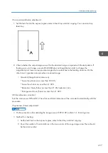
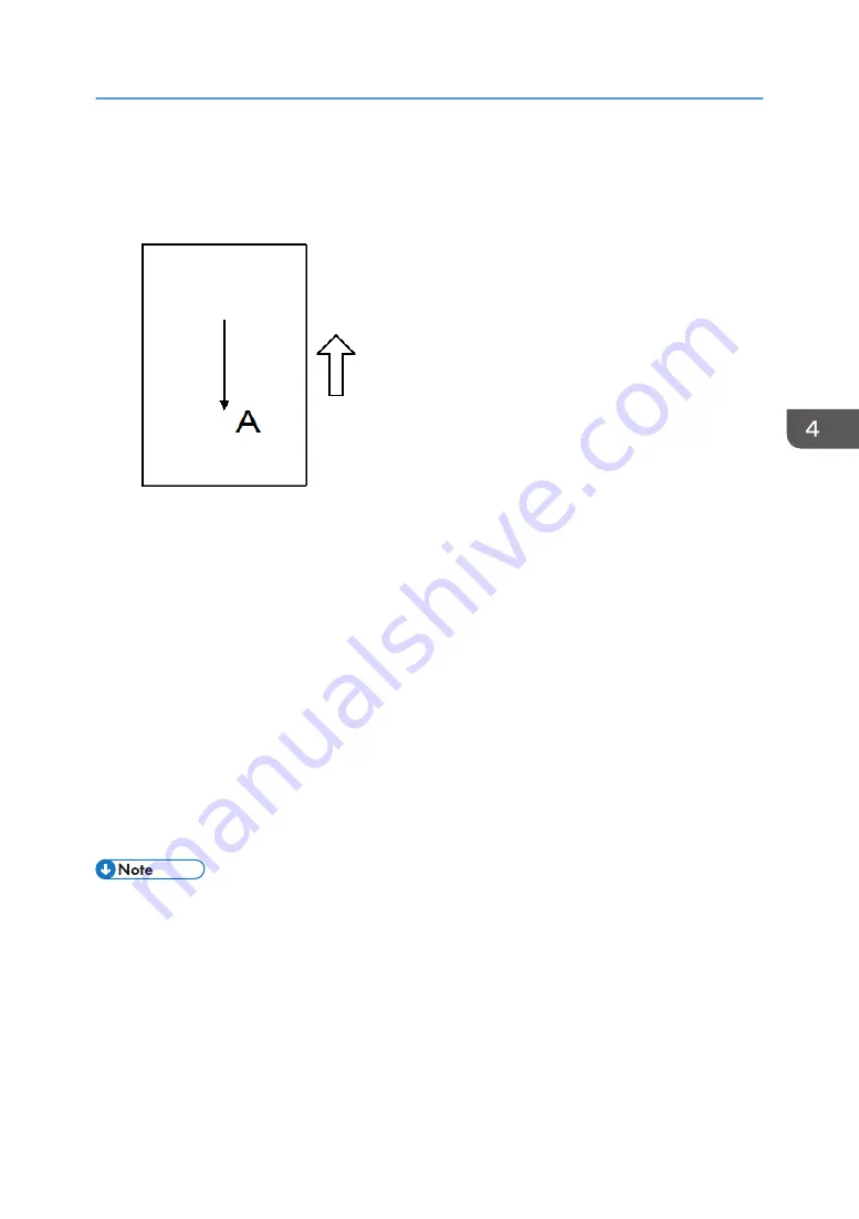
1. Set the test chart on the exposure glass, select a feed tray and start copying. You can select any

feed tray.

2. Check whether the output image was within the standard range compared with the test pattern. If

the image is out of range, execute SP4-008(Sub scan Magnification Adj.) to change the
magnification. A lower value provides images that are stretched in the feeding direction. On the
other hand, a greater value provides a reduced image.

• Standard (Magnification tolerance)

* Same Size: Main scan: Less than ±0.55%
* Same Size: Sub scan: Less than ±1.00%
* Reduction: Main/Sub scan: Less than ±1.00/reduction ratio
* Enlargement: Main/Sub scan: Less than ±1.00%

<White reference correction>
Turn the main power Off and On. The white and black reference will be corrected automatically with this
procedure.
<Squareness (Skew) adjustment>

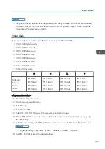
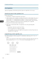
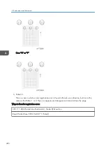
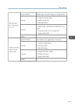
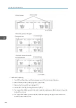
• Do this procedure after adjusting the image area with SP2-109: pattern 14 - trimming area.
• Method for checking

1. Set the test chart on the exposure glass, select a feed tray and start copying.
2. Count the number of horizontal bars in the two corners of the copy image area. There should

be the same number.

Adjustment after replacing

437

Содержание MET-C1

Страница 1: ...Model MET C1 Machine Code D176 D177 Field Service Manual September 2013 Subject to change ...

Страница 2: ......

Страница 3: ... by accident it may cause temporary eye discomfort Immediately wash eyes with plenty of water If unsuccessful get medical attention 2 The copier which use high voltage power source can generate ozone gas High ozone density is harmful to human health Therefore the machine must be installed in a well ventilated room Observance of Electrical Safety Standards The copier and its peripherals must be ser...

Страница 4: ...fety The Center for Devices and Radiological Health CDRH prohibits the repair of laser based optical units in the field The optical housing unit can only be repaired in a factory or at a location with the requisite equipment The laser subsystem is replaceable in the field by a qualified Customer Engineer The laser chassis is not repairable in the field Customer engineers are therefore directed to ...

Страница 5: ...ally hazardous situation Failure to obey a Caution could result in minor or moderate injury or damage to the machine or other property Obey these guidelines to avoid problems such as misfeeds damage to originals loss of valuable data and to prevent damage to the machine This information provides tips and advice about how to best service the machine 3 ...

Страница 6: ...trademarks of Microsoft Corporation in the United States and or other countries PostScript is a registered trademark of Adobe Systems Incorporated PCL is a registered trademark of Hewlett Packard Company Ethernet is a registered trademark of Xerox Corporation PowerPC is a registered trademark of International Business Machines Corporation Other product names used herein are for identification purp...

Страница 7: ...ation Product Overview 21 Component Layout 21 Scanner Unit 22 Laser Exposure Unit 23 Image Transfer Unit 24 PCDU 25 Toner Supply Waste Toner Bottle 26 Paper Feed Unit 27 Duplex Unit 28 By pass unit 29 Fusing Unit 30 Paper Transfer Paper Exit 31 Air Flow 32 Drive Unit 33 Board Switch 34 Paper Path 35 Drive Layout 37 Machine Codes and Peripherals Configuration 39 Diagram 39 Options 39 Specifications...

Страница 8: ...3 Important notice on security issues 53 Overview 53 Password setting procedure 54 Installation Flow Chart 59 Accessory Check 59 Installation Procedure 61 Removal of packing materials and shipping retainers Removal of PCDU seal 61 Toner bottle installation 66 Attaching the optical cloth pocket 67 Attaching paper output tray parts 68 Connecting the power cord 68 Image quality test settings 69 Image...

Страница 9: ...tallation Procedure 82 ARDF DF3090 85 Accessory Check 85 Installation Procedure 85 When feeding thin paper 90 1 Bin Tray BN3110 91 Accessory Check 91 Installation Procedure 91 Internal Shift Tray SH3070 99 Accessory Check 99 Installation procedure 99 Side Tray Type M3 104 Accessory Check 104 Installation procedure 105 Internal Finisher SR3130 109 Accessory Check 109 Installation Procedure 109 Punc...

Страница 10: ... 158 Accessory Check 158 Installation procedure 158 Key Counter 158 Smart Card Reader Built in Unit Type M2 D739 36 160 Accessory Check 160 Installation Procedure 160 Imageable Area Extension Unit Type M3 166 Accessory Check 166 Installation Procedure 166 When you forgot to change the SP 167 Internal Options 168 List of Slots 168 IEEE 802 11a g n Interface Unit Type M2 170 Accessory Check 170 Inst...

Страница 11: ...D 180 Accessory Check 180 Installation procedure 180 SD Card Option 182 SD Card Slots 182 List of Slots Used 182 SD Card Appli Move 184 Overview 184 Move Exec 185 Undo Exec 187 Data Overwrite Security Unit Type H D377 189 Overview 189 Component List 189 Before You Begin the Procedure 189 Seal Check and Removal 190 Installation Procedure 191 Camera Direct Print Card Type M3 192 Accessory Check 192 ...

Страница 12: ... Procedure 205 Installation Procedure 205 HDD Encryption 206 Before You Begin the Procedure 206 Enable Encryption Setting 207 Check the Encryption Settings 210 Print the encryption key 211 Memory Unit Type M3 2GB 213 Accessory Check 213 Installation Procedure 213 3 Preventive Maintenance PM Parts Settings 215 Replacement procedure of the PM parts 215 After installing the new PM parts 216 Preparati...

Страница 13: ...ar Lower Cover 231 Scanner Rear Cover 232 Scanner Rear Cover Small 232 Right Rear Cover 232 Right Upper Cover 233 Main power switch cover 234 Waste Toner Cover 234 Reverse Tray 235 Paper Exit Tray 236 Paper Exit Cover 236 Paper Exit Lower Cover 236 Paper Exit Front Cover 237 Inner Upper Cover 238 Inner Lower Cover 239 Operation Panel Unit 240 Operation Panel 240 Board A 241 Board B 243 Board C 244...

Страница 14: ...ition Sensor 261 Adjusting the Scanner Wire 262 Scanner Wire Front 262 Scanner wire assembly front side 265 Scanner position adjustment 267 Scanner Wire Rear 268 Scanner Wire Assembly rear side 271 Modifying the Scanner contact contactless when using ARDF 272 Procedure for the ADF 272 Procedure for the scanner 275 Laser Unit 276 Laser Unit 276 Before Replacement 277 Removing 277 Installing a New L...

Страница 15: ...nsfer Belt Unit 293 Adjustment before replacing the image transfer belt unit 294 Replacement 294 Image Transfer Cleaning Unit 297 Adjustment before replacing the image transfer cleaning unit 298 Replacement 298 Image Transfer Belt 301 Replacement 301 Adjustment after replacing the Image transfer belt 304 Paper Transfer Roller 305 Paper Transfer Roller Unit 305 Adjustment before replacing the paper...

Страница 16: ...ng Drive Unit 318 PCU Motor CMY 320 Development Motor CMY 320 Development solenoid 320 Fusing Motor 322 Paper Exit Pressure Release Motor 322 Duplex Entrance Motor 323 Toner Transport Motor 324 Sub Hopper 325 K 325 C 325 M 327 Y 328 Toner End Sensor 329 Toner Bottle Drive Motor 330 K 330 C 330 M 331 Y 331 ID Chip 331 K 331 C 332 M 332 Y 333 Transport screw 334 Y 334 14 ...

Страница 17: ... Lower Cover 344 Fusing Front Cover 345 Fusing Rear Cover 346 Heating sleeve unit 347 Replacement 347 How to cancel SC544 02 SC554 02 with a new unit detection fuse 350 Pressure Roller 351 Adjustment before replacing the pressure roller 351 Replacement 351 Thermostat Unit 353 Non contact Thermistor Unit 354 Fusing Thermistor 355 Fusing Thermopile Unit 355 Pressure Roller HP Sensor 356 Fusing Shiel...

Страница 18: ...or 373 Limit Sensor 374 Paper End Sensor 375 Registration Sensor 376 By pass Tray Unit 377 By pass Tray 377 By pass Paper End Sensor 379 By pass Pick up Roller 380 By pass Paper Feed Roller 381 By pass Separation Roller 381 Torque Limiter 382 Duplex Unit 383 Duplex Unit 383 Duplex By pass Motor 385 Duplex Entrance Sensor 387 Duplex Exit Sensor 388 Electrical Components 391 Overview 391 Printed Cir...

Страница 19: ...ort IOB 405 HVP CB 406 When removing the HVP CB together with its bracket 409 Fans Filters 411 Odor Filter 411 Development Intake Fan Right 411 Development Intake Fan Left 412 Ozone Exhaust Fan 413 Paper Exit Cooling Fan 413 Fusing Exhaust Heat Fan 414 Toner Supply Cooling Fan 415 PSU Cooling Fan 416 Power Box Cooling Fan 417 Image Adjustment 418 Auto Color Calibration 418 Printer Gamma Correction...

Страница 20: ...osis outline 445 Controller self diagnosis flowchart 446 Service Call 101 195 450 SC100 Engine Scanning 450 Service Call 201 285 457 SC200 Engine Image Writing 457 Service Call 324 396 463 SC300 Engine Charge Development 463 Service Call 441 498 468 SC400 Engine Around the Drum 468 Service Call 501 584 474 SC500 Engine Paper transport 1 Paper Feed Duplex Transport 474 Service Call 620 689 520 SC60...

Страница 21: ... Clearing a paper jam 629 Paper Jam History 629 History checking method 629 Paper Jam Display 630 Jam Codes and Display Codes 630 Paper Size Code 634 Image Quality 635 When an abnormal image is generated 635 Roller pitch 636 OCR Unit Type M2 637 Recovery procedure 637 Electrical Component Defects 638 6 Environment Environment 641 Energy Saver Modes 641 Timer Settings 642 Return to Stand by Mode 64...

Страница 22: ...20 ...

Страница 23: ...1 Product Information Product Overview Component Layout No Description No Description 1 Scanner Unit 6 Paper Feed Unit 2 Paper Exit Unit 7 Waste Toner Unit 21 ...

Страница 24: ...8 Laser Exposure Unit 4 Paper Transfer Unit 9 PCDU 5 Duplex Unit 10 Image Transfer Unit Scanner Unit No Description No Description 1 Operation Panel 6 Scanner Input Output SIO board 2 Scanner lamp Unit LED 7 Scanner motor 1 Product Information 22 ...

Страница 25: ...4 Anti condensation heater Scanner heater 1 9 Auto Paper Size detection APS sensor 2 5 DF Position Sensor 10 Sensor Board Unit SBU 1 Option Laser Exposure Unit No Description No Description 1 Skew motor 5 Polygon mirror motor 2 Synchronizing detector board M Y S 6 LD Drive Board M Y Product Overview 23 ...

Страница 26: ...Skew motor 8 Synchronizing detector board Bk C S Image Transfer Unit No Description 1 Interlock switch Front cover LD Safety Switch 2 Interlock switch Duplex Unit LD Safety Switch 3 ITB contact and release sensor 4 TM P sensor shutter solenoid 1 Product Information 24 ...

Страница 27: ...No Description 5 TM P sensor rear 6 TM P sensor center 7 TM P sensor front PCDU No Description No Description 1 PCDU Y 3 PCDU C 2 PCDU M 4 PCDU Bk Product Overview 25 ...

Страница 28: ...2 Toner bottle drive motor Y 11 Toner transport motor M 3 ID chip M 12 Toner end sensor M 4 Toner bottle drive motor M 13 Toner transport motor C 5 ID chip C 14 Toner end sensor C 6 Toner bottle drive motor C 15 Toner end sensor Bk 7 ID chip Bk 16 Toner transport motor Bk 1 Product Information 26 ...

Страница 29: ...iption 1 Tray set switch 1st feed tray 10 Paper feed sensor 1st feed tray 2 Lift motor 1st feed tray 11 Paper end sensor 2nd feed tray 3 Tray set switch 2nd feed tray 12 Limit sensor 2nd feed tray 4 Lift motor 2nd feed tray 13 Transport sensor 1st feed tray 5 Registration sensor 14 Paper end sensor 1st feed tray 6 Size switch 2nd Feed Tray 15 Limit sensor 1st feed tray Product Overview 27 ...

Страница 30: ...sor 2nd Feed Tray 17 Pick up solenoid 1st feed tray 9 Transport sensor 2nd Feed Tray Duplex Unit No Description No Description 1 Duplex entrance motor 5 By pass pick up solenoid 2 Right door open close switch 6 By pass Duplex motor 3 Duplex entrance sensor 7 By pass paper end sensor 1 Product Information 28 ...

Страница 31: ...uplex exit sensor By pass unit No Description No Description 1 Main Scanning Sensor 5 By pass length sensor 2 By pass length sensor 6 Side Fence Drive Motor 3 Main Scanning Sensor 7 Side Fence Paper Contact sensor 4 Side Fence Paper Contact sensor Product Overview 29 ...

Страница 32: ...Shield position sensor Lower 10 Thermostat edge 3 Shield position sensor Upper 11 Thermostat center 4 Thermopile edge 12 NC sensor center 5 Thermopile center 13 NC sensor edge 6 Fusing exit sensor 14 Thermistor edge 7 Shield drive motor 15 Shield sensor 1 2 8 Fusing heater 1 Product Information 30 ...

Страница 33: ...fer Paper Exit No Description No Description 1 Inversion Motor 5 Fusing entrance sensor 2 Inversion Sensor 6 Fusing jam sensor 3 Paper exit sensor 7 Paper exit solenoid 4 PTR open close sensor Product Overview 31 ...

Страница 34: ... Description 1 Paper exit cooling fan 5 Ozone exhaust fan 2 Development intake fan right 6 Thermistor 3 Development intake fan left 7 Toner supply cooling fan 4 PSU cooling fan 8 Fusing exhaust heat fan 1 Product Information 32 ...

Страница 35: ...g IOB 7 Registration Motor 2 Development Motor CMY 8 PCU Motor CMY 3 Development Motor Black 9 Phase sensor 4 PCU Black Image Transfer Motor 10 Fusing Motor 5 Paper Feed Motor 11 Paper Exit Pressure Release Motor 6 Transport Motor Product Overview 33 ...

Страница 36: ...on No Description 1 Power switch 7 PSU DC Power 2 Interlock switch front cover 8 PSU AC controller board 3 HVP_TTS 9 BCU 4 Control board 10 Controller box cooling fan 5 HDD 11 IPU 6 Paper Transport IOB 1 Product Information 34 ...

Страница 37: ...Paper Path No Description No Description 1 ARDF DF3090 3 Internal Finisher SR3130 2 Paper Feed Unit PB3160 Product Overview 35 ...

Страница 38: ...No Description No Description 1 Platen Cover PN2000 3 Side Tray Type M3 2 Paper Feed Unit PB3150 4 1 Bin Tray BN3110 1 Product Information 36 ...

Страница 39: ...rive motor C 2 Duplex By pass motor 13 Toner bottle drive motor M 3 Transport motor 14 Toner bottle drive motor Y 4 Registration motor 15 Toner transport motor Y 5 Paper transfer contact motor 16 Toner transport motor M 6 Fusing motor 17 Toner transport motor C Product Overview 37 ...

Страница 40: ...ease motor 18 Toner transport motor Bk 8 Duplex entrance motor 19 Development Motor CMY 9 Inversion motor 20 PCU Motor CMY 10 Scanner motor 21 Development Motor Black 11 Toner bottle drive motor Bk 22 PCU Black Image Transfer Motor 1 Product Information 38 ...

Страница 41: ...e Codes and Peripherals Configuration Diagram Options Mainframe ARDF as standard NA EU Item Machine Code Call out Platen Cover PN 2000 D700 EU Asia TWN CHN KOR 1 Machine Codes and Peripherals Configuration 39 ...

Страница 42: ... D691 8 Side Tray Type M3 D725 9 Internal Finisher SR3130 D690 10 Internal Finisher SR3180 D766 11 Handset HS3020 D739 05 12 Punch Unit PU3040 NA D716 17 Punch Unit PU3040 EU D716 27 Punch Unit PU3040 SC D716 28 Fax Option Type M3 D163 G3 Interface Unit Type M3 D163 Memory Unit Type B 32MB G578 IEEE 802 11a g n Interface Unit Type M2 D164 01 Memory Unit Type M3 2GB D164 03 Fax Connection Unit Type...

Страница 43: ...166 26 EU D166 27 Asia Smart Card Reader Built in Unit Type M2 D739 06 Imageable Area Extension Unit Type M3 D739 07 Marker Type 30 H903 ADF Handle Type C D593 81 IEEE 1284 Interface Board Type A B679 Bluetooth Interface Unit Type D D566 File Format Converter Type E D377 04 Copy Data Security Unit Type G D640 Optional Counter Interface Unit Type A B870 Key Counter Bracket Type M3 D739 09 Card Read...

Страница 44: ...Font Package for SAP R 10 License B869 02 Unicode Font Package for SAP R 100 License B869 03 DataOverwriteSecurity Unit Type H D377 06 Waste Toner Bottle MP C6003 D860 01 External Keyboard Bracket Type M3 D739 10 1 Product Information 42 ...

Страница 45: ...Specifications See Appendices for the following information General Specifications Supported Paper Sizes Software Accessories Optional Equipment Other Specifications Specifications 43 ...

Страница 46: ...o pick up solenoid No paper feed sensor main frame only No double feed detection Double feed detection D150 only Tray pull in mechanism Duplex Driving Main frame Item D176 D177 D146 D147 D148 D149 D150 Duplex Exit Duplex 52 169 g m2 No paper exit full sensor Duplex 52 256g m2 Jam detection LED D148 D149 D150 only Paper Feed Capacity Up to 2300 maximum 550 4 100 Up to 4700 maximum 550 2 1000 2 1500...

Страница 47: ...unction D150 only Air flow 8 fans D146 D147 8 fans D148 D149 D150 11 fans PCDU Item D176 D177 D146 D147 D148 D149 D150 PCDU DC charge roller Contact type No lubricant bar 3 layer drum Discharge lamp is in the mainframe Correction SP value must be input when PCU is replaced AC charge roller No contact type Lubricant bar 4 layer drum No discharge lamp Dev Unit Two mixing augers two way circulation s...

Страница 48: ...onent Item D176 D177 D146 D147 D148 D149 D150 HVP CB Correction SP value must be input when this board is replaced No SP value New features of D176 D177 Item Description SFU Smart Firmware Update New feature of firmware update Firmware can be updated through a simple operation at the operation panel only if the machine is connected to Remote 1 Product Information 46 ...

Страница 49: ...replacement of specific parts New PCU has unstable charging characteristics and sensitive to charging voltage When replacing parts below please make sure to correct SP values to optimize imaging process PCU HVP CB Guidance for Those Who are Familiar with Similar Products 47 ...

Страница 50: ...1 Product Information 48 ...

Страница 51: ...uirements Environment Temperature Range 10 C to 32 C 50 F to 90 F Humidity Range 15 to 80 RH Ambient Illumination Less than 1 500 lux do not expose to direct sunlight Ventilation Room air should turn over at least 30 m3 hr person 49 ...

Страница 52: ...ll the machine at any location over 2 000 m 6 500 ft above sea level D135 for NA can be installed only up to 2 500m 8 202 ft 4 Place the main machine on a strong and level base Inclination on any side should be no more than 5 mm 0 2 5 Do not place the machine where it may be subjected to strong vibrations Machine Space Requirements A Left Over 100 mm 3 9 B Rear Over 100 mm 3 9 C Right Over 100 mm ...

Страница 53: ...he clearance shown above Machine Dimensions A 1210 mm D 247 mm B 1030 mm E 788 mm C 180 mm F 587mm Power Requirements Insert the plug firmly in the outlet Do not use an outlet extension plug or cord Ground the machine Installation Requirements 51 ...

Страница 54: ...ltage Rated current consumption Permissible voltage fluctuation NA 120 to 127V 12A or more Imaging 108V 120V 10 to 138V 127V 8 66 Motions 102V 120V 15 to 138V 127V 8 66 EU 220 to 240V 10A Imaging 10 Motions 15 AP CHN TWN 110 V 20A 2 Installation 52 ...

Страница 55: ...ase this screen with the following procedure in the case that they think there is no need to set the password 1 On the Program Change Administrator screen press Change next to Supervisor and then touch OK without inputting any password 2 Touch OK again when the Confirm password display shows up 3 For Administrator 1 do the same procedure as steps 1 and 2 4 Press the OK button then the home display...

Страница 56: ...rd window won t display The passwords for Supervisor or Administrator 1 to 4 can be set via System Settings But the Program Change Administrator screen appears every time the power switch is turned ON if the passwords are input this way So we recommend the customers to set the passwords via network or the Program Change Administrator screen 1 Install the MFP 2 Turn the main power switch ON 3 Chang...

Страница 57: ...4 Input the password 5 Press OK Main Machine Installation 55 ...

Страница 58: ...6 Confirm the Password 7 Press OK 2 Installation 56 ...

Страница 59: ...8 Change the Administrator 1 login password 9 Input the password 10 Press OK Main Machine Installation 57 ...

Страница 60: ...11 Confirm the password 12 Press OK 13 Cycle the power OFF ON 2 Installation 58 ...

Страница 61: ...Installation Flow Chart Accessory Check Description Q ty Power Supply Cord 1 Operation Instruction User Guide 1 Main Machine Installation 59 ...

Страница 62: ...e Glass 1 Image Transfer Cover 1 TAPPING SCREW 1 Plate Logo 1 Sheet Logo 1 End Fence Output Tray 1 Sheet Application Multi Language Blank 1 Sheet Application Multi Language EU 1 Sheet Journal Blank 1 Sheet Safety EU 1 Sheet EMC EU 1 Sheet Name TEL CHN 1 Sheet EULA 1 Sheet Security Password 1 Seal Caution 1 Decal Paper Tray 1 Decal Original Table 1 Decal Caution Original Multi Language 1 2 Installa...

Страница 63: ...he same time Then install the machine and other options Keep the shipping retainers after you install the machine You may need them in the future if you transport the machine to another location Removal of packing materials and shipping retainers Removal of PCDU seal 1 Remove the machine from the box and check the items in the package Before lifting up the machine as there are hidden handles remov...

Страница 64: ...en you lift the machine hold the correct parts as shown in the diagram below Do not lift by holding the scanner unit etc because this might deform the machine or break the exterior covers 2 Installation 62 ...

Страница 65: ...2 Remove the orange tape and retainers on the outside Main Machine Installation 63 ...

Страница 66: ...3 Remove the paper size decal A on the exposure glass 4 Pull out the 1st and 2nd paper feed tray and remove the orange tape 5 Remove the scanner support A 2 Installation 64 ...

Страница 67: ...6 Open the front cover and store the scanner support in the storage location A The factory setting sheet is kept in the position A 7 Carefully pull out the heat seal A Main Machine Installation 65 ...

Страница 68: ...8 Secure the ITB unit front cover A x1 Toner bottle installation 1 Open the front cover 2 Shake the toner bottle Bk 5 to 6 times 3 Remove the toner bottle protection cap A 2 Installation 66 ...

Страница 69: ...wer is turned on it will fill up for the first time in about 5 minutes Attaching the optical cloth pocket 1 Clean the adhesive surface of the optical cloth pocket with an alcohol soaked cloth 2 Attach the optical cloth pocket A to the left side of the scanner and put the optical cloth into the pocket Main Machine Installation 67 ...

Страница 70: ...he paper output tray First insert and attach the front pin inside the blue circle Connecting the power cord Do not use any connectors other than the power cord provided Also do not use an extension cord 1 Connect the power cord to the machine 2 Installation 68 ...

Страница 71: ...py image with the test chart Paper setting 1 If necessary adjust the registration for the paper feed tray SP1 002 002 Side to Side Registration Paper Tray 1 SP1 002 003 Side to Side Registration Paper Tray 2 Moving the Machine This section shows you how to manually move the machine from one floor to another floor See the section Transporting the Machine if you have to pack the machine and move it ...

Страница 72: ... When moving the machine do not press against the ADF 2 Installation 70 ...

Страница 73: ... power OFF and unplug the power supply cord from the wall socket If it is installed with the power on it may result in an electric shock or a malfunction Be sure to join the machine to the paper feed unit so as to prevent equipment from falling over If they are not connected they may move and fall over resulting in injury 1 Remove the orange tape and retainers 2 Remove the items provided fixing sc...

Страница 74: ...achine to deform Do not put the machine down on the paper feed unit as a temporary resting place This may cause the paper feed unit to deform Always connect the machine and paper feed unit properly 3 Pull out the 2nd paper feed tray 4 Using securing bracket as a screwdriver fix the machine to the feed unit spring washer screw M4 10 1 2 Installation 72 ...

Страница 75: ...ght at the rear of the machine screws 1 each 6 Return the paper feed tray to the machine 7 Attach the decals as shown below A Tray number decal B Paper size decal The tray number decal and paper size decal are packaged together with the machine Paper Feed Unit PB3210 73 ...

Страница 76: ... shipped Do not remove it 10 Turn the power switch ON 11 Set the paper and check that the paper size set in the paper feed tray is displayed on the operation panel 12 Adjust the registration for the paper feed unit SP1 002 004 Side to Side Registration Paper Tray 3 SP1 002 005 Side to Side Registration Paper Tray 4 2 Installation 74 ...

Страница 77: ...in injury When installing this option turn the machine power OFF and unplug the power supply cord from the wall socket If it is installed with the power on it may result in an electric shock or a malfunction Be sure to join the machine to the paper feed unit so as to prevent equipment from falling over If they are not connected they may move and fall over resulting in injury 1 Remove the orange ta...

Страница 78: ...lding the scanner unit etc because this may cause the machine to deform Do not put the machine down on the paper feed unit as a temporary resting place This may cause the paper feed unit to deform Always connect the machine and paper feed unit properly 4 Pull out the 2nd paper feed tray 5 Using a securing bracket as a screwdriver fix the machine to the feed unit spring washer screw M4 10 1 2 Insta...

Страница 79: ...8 Attach the decals as shown below A Tray number decal B Paper size decal The tray number decal and paper size decal are packaged together with the machine 9 Connect the power cord to the machine 10 Turn the power switch ON 11 Set the paper and check that the paper size set in the paper feed tray is displayed on the operation panel Paper Feed Unit PB3150 77 ...

Страница 80: ...12 Adjust the registration for the paper feed unit SP1 002 004 Side to Side Registration Paper Tray 3 2 Installation 78 ...

Страница 81: ...lifted with force handled carelessly or dropped it will result in an injury If installing this option turn the power to the machine off and unplug the power plug from the wall socket If it is installed when the power is on it will result in an electric shock or malfunction Be sure to join the machine and caster table to prevent equipment from falling over If it is not joined the machine will move ...

Страница 82: ... 2nd paper feed tray 4 Using a securing bracket fix the machine to the paper tray unit spring washer screw M4 10 1 5 Attach the securing brackets A at 2 positions to left and right at the rear of the machine screws 1 each 6 Return the paper feed tray to the machine How to place the Paper Feed Unit PB3150 on the caster table 1 Attach the 3 locating pins 2 Place the paper feed unit on the caster tab...

Страница 83: ...6 Return the paper feed tray to the machine 7 Holding the grips on the machine align with the locating pins of the paper feed unit and place the machine on the paper feed unit Caster Table Type M3 81 ...

Страница 84: ...ssories indicated below No Description Q ty 1 COVER PRESSURE PLATE 1 2 SHEET PRESSURE PLATE ASS Y 1 3 SUPPORTER FEELER 1 4 GUIDE PIN PRESSURE PLATE HINGE 2 Installation Procedure Unplug the machine power cord before starting the following procedure 2 Installation 82 ...

Страница 85: ...1 Install the stepped screws 2 2 Install the feeler guide A 3 Install the platen cover A Platen Cover PN2000 83 ...

Страница 86: ... 5 Line up the rear left corner of the platen sheet flush against corner B on the exposure glass 6 Close the platen cover 7 Open the platen cover 8 Press the surface of the platen sheet gently to fix it on the platen cover securely 2 Installation 84 ...

Страница 87: ...iption Q ty 1 TAPPING SCREW 3X6 2 2 SCREW POSITIONING HINGE 1 3 SCREW HINGE INNER BACK 1 4 FULL DUG POINT SCREW FIX HINGE 2 5 Stamp 1 6 DECAL CAUTION ORIGINAL MANY LANGUAGES 1 Installation Procedure Unplug the copier power cord before starting the following procedure 1 All tapes and shipping retainers ARDF DF3090 85 ...

Страница 88: ...aligning the screw keyholes B of the ARDF support plate over the stud screws 4 Slide the ARDF toward the front of the machine 5 Secure the ARDF with the two knob screws C 6 Align the rear left corner of the platen sheet A with the corner B on the exposure glass 7 Close the ARDF 2 Installation 86 ...

Страница 89: ...correctly attached 9 Lift the ARDF original tray 10 Slide the stamp holder A out and install the stamp cartridge in it if necessary After the stamp installation be sure to slide the holder in correctly If not jam detection J001 will occur ARDF DF3090 87 ...

Страница 90: ...11 Attach the decals A B to the top cover as shown Choose the language that you want 12 Scanner rear cover A 3 2 Installation 88 ...

Страница 91: ...13 Connect the harness A 14 Attach the bracket A 1 15 Fasten the grounding wire A 1 16 Attach the rear cover ARDF DF3090 89 ...

Страница 92: ... are not adjust the registrations and image skew see ARDF Image Adjustment in the Replacements and Adjustments chapter When feeding thin paper When feeding thin paper adjust the sliding tray to the point shown below A When feeding normal paper adjust the sliding tray to the point shown below B If not it may cause problems as follows Original jam Original curl Originals cannot be stacked neatly 2 I...

Страница 93: ... 2 Installation Procedure When installing this option turn the machine power off and unplug the power plug from the wall socket If it is installed with the power on it will result in an electric shock or a malfunction If you install this option together with Side Tray Type M3 first install this option and then install Side Tray Type M3 1 Bin Tray BN3110 91 ...

Страница 94: ...d fence in advance 1 Remove the orange tape and shipping retainers 2 Remove the enclosed items fixing screws etc 3 Open the right cover 4 Main power switch cover A 1 Remember that there is a tab at the positions in the blue circles 5 Paper output tray A 6 Open the front cover 2 Installation 92 ...

Страница 95: ...7 Upper left cover A 1 8 Left rear cover A 2 1 Bin Tray BN3110 93 ...

Страница 96: ...9 Inverter tray A tray support rod cover B 1 10 Paper output cover A 1 2 Installation 94 ...

Страница 97: ...11 Attach the gear A provided 12 Attach the 1 bin tray unit A 1 2 Take care that the harness is not trapped between the 1 bin tray unit and the machine frame 1 Bin Tray BN3110 95 ...

Страница 98: ...13 Attach the harness provided 14 Attach the tray support bar A 1 Take out the harness attached in the previous step from the position in the blue circle 2 Installation 96 ...

Страница 99: ...15 Hook the 1 bin tray A onto the 1 bin tray unit aligning the positions in the blue circles 16 Connect the harness to the 1 bin tray and bring it around 1 Bin Tray BN3110 97 ...

Страница 100: ...tach the harness cover A 18 Attach the left rear cover upper left cover and main power switch cover and close the duplex unit 19 Turn the power switch ON 20 Check that output to this tray can be selected on the operation panel and check operation 2 Installation 98 ...

Страница 101: ... 2 Installation procedure When installing this option turn the power to the machine off and unplug the power plug from the wall socket If it is installed when the power is on it will result in an electric shock or a malfunction 1 Remove the filament tape and packing material 2 Remove the enclosed items Internal Shift Tray SH3070 99 ...

Страница 102: ...3 Attach the part B to the shift tray A 4 Paper output tray A 2 Installation 100 ...

Страница 103: ...5 Connector cover A 6 Attach the shift tray 7 Open the right cover 8 Main power switch cover A 1 Remember that there is a claw at the positions in the blue circles Internal Shift Tray SH3070 101 ...

Страница 104: ...9 Paper output cover A 1 10 Attach the shift tray feeler A 2 Installation 102 ...

Страница 105: ...f the paper output cover 13 Attach the paper output cover and main power switch cover and close the duplex unit 14 Turn the power switch ON 15 Check that paper output to the shift tray can be selected at the operation panel and check the operation Internal Shift Tray SH3070 103 ...

Страница 106: ...ory Check No Description Q ty 1 TRAY LEFT EXIT 1 2 EXTENSION TRAY LEFT EXIT 1 2 EXTENSION TRAY EXIT UPPER 1 3 STAY COUPLING 1 4 SCREW M4 1 5 TAPPING SCREW 3X8 1 6 TAPPING SCREW 4X10 1 7 BRACKET RIGHT FRONT 1 2 Installation 104 ...

Страница 107: ...ide tray cannot be used together with Internal Shift Tray SH3070 To use together with the 1 Bin Tray BN3110 attach the 1 Bin Tray BN3110 first before installing the side tray 1 Remove the orange tape and shipping retainers 2 Remove the enclosed items fixing screws etc 3 Paper output tray A 4 Open the right cover 5 Main power switch cover A 1 Remember that there is a claw at the positions in the bl...

Страница 108: ...6 Connector cover A 7 Attach the bracket A 1 8 Attach the main power switch cover and close the duplex unit 2 Installation 106 ...

Страница 109: ...the side tray unit A to the machine and fix with a knob screw 1 10 Attach the fixing plate A 1 11 Attach the upper extension tray A and the left extension tray B 12 Turn the power switch ON Side Tray Type M3 107 ...

Страница 110: ...13 Check that paper output to the side tray can be selected at the operation panel and check the operation 2 Installation 108 ...

Страница 111: ...r 1 3 Caster Stand 2 4 Bottom Plate 1 5 Left Lower Cover 1 6 Entrance Guide Plate 1 Screw M3 6 6 Tapping Screw M4 x 6 1 Decal EMC Address 1 Installation Procedure When you install this option turn off the power to the machine and unplug the power plug from the wall socket Internal Finisher SR3130 109 ...

Страница 112: ...e 1 Bin Tray BN3110 after attaching the bottom plate of this option attach the 1 Bin Tray BN3110 and then install this option To use together with the Punch Unit PU3040 first attach the Punch Unit PU3040 before installing this option 1 Remove the orange tape and shipping retainers 2 Remove the package items fixing screws etc 3 Open the front cover 4 Paper output tray A 2 Installation 110 ...

Страница 113: ...5 Upper left cover A 1 6 Left rear cover A 2 Internal Finisher SR3130 111 ...

Страница 114: ...7 Inverter tray A tray support plate B 8 Open the right cover 9 Main power switch cover A 1 Remember that there is a claw at each location in the blue circles 2 Installation 112 ...

Страница 115: ...10 Paper output cover A 1 11 Connector cover A 12 Paper output lower cover A 3 Internal Finisher SR3130 113 ...

Страница 116: ...13 Upper rear inner cover A 2 14 Install a screw A removed in step 12 2 Installation 114 ...

Страница 117: ...C D 3 The following procedure is the easiest way to set this component 1 Slip the bottom plate A into the position in the blue circle B 2 Insert the bottom plate A into the hole in the blue circle C 3 When the bottom plate A is picked up see below it can be inserted into the hole in the blue circle D Internal Finisher SR3130 115 ...

Страница 118: ...it installation for fitting the punch unit refer to Step 3 and later of the Punch unit installation procedure 18 Attach the connector cover 19 Attach the main power switch cover and close the right cover 20 Slide the finisher right front cover A from left to right to attach it 1 21 Attach the inverter tray 2 Installation 116 ...

Страница 119: ...ong the rail of the bottom plate from the left hand side of the machine to attach it 1 Hold the front side A of the inner finisher as shown below to check if the inner finisher is correctly set in the rail of the bottom plate 24 Attach the left rear cover Internal Finisher SR3130 117 ...

Страница 120: ...ster stands A Because the weight is biased to the right of the machine if the inner finisher is installed caster stands are required on the left side Because they are included with the finisher install these components at the same time as you install the inner finisher 2 Installation 118 ...

Страница 121: ...e stapler unit then set the staple cartridge A 29 Turn the power switch on 30 Check that the finisher can be selected at the operation panel and check the finisher operation Also when punch unit is installed check the punching operation Internal Finisher SR3130 119 ...

Страница 122: ...ccessory Check No Description Q ty 1 TONER HOPPER ASS Y 1 2 COVER FRONT PUNCH UNIT ASS Y 1 3 COVER TRAY LOWER FRONT 1 4 COVER TRAY LOWER REAR 1 5 HOLDER LOCK RELEASE PUNCH 1 SCREW M3X6 3 KNOB SCREW M3 1 2 Installation 120 ...

Страница 123: ...ttach this option before installing the Internal Finisher SR3130 If the Internal Finisher SR3130 is already attached attach this option after removing the finisher 1 Take out from the box and remove the filament tape and packing material 2 Remove the finisher and finisher front right cover from the machine 3 Perform steps 1 to 17 of the installation procedure for the Internal finisher SR3130 4 Cha...

Страница 124: ...ch the main power switch cover 7 Pass the shafts B of the punch unit A through the bearings C of the bottom plate and attach to the machine 1 knob screw If it is difficult to insert by probing look from the side while you insert it into the bearings of the bottom plate 2 Installation 122 ...

Страница 125: ... installing the punch unit in a finisher that is already installed remove the relay guide plate A 2 This step is unnecessary when installing the finisher and punch unit at the same time Punch Unit PU3040 123 ...

Страница 126: ...9 Attach the front right cover A provided inserting the claws 1 10 Insert the hopper A 2 Installation 124 ...

Страница 127: ...e bottom plate from the left hand side of the machine to attach it 1 12 Attach the components A and B to the finisher 2 13 Attach the left rear cover 14 Insert the upper left cover A from the front and slide it to attach it Punch Unit PU3040 125 ...

Страница 128: ...achine if the inner finisher is installed anti tip components are required on the left side Because they are included with the finisher install these components at the same time as you install the inner finisher 16 Connect the interface cable to the machine 2 Installation 126 ...

Страница 129: ...e forward the stapler unit then set the stapler A 18 Turn the power switch on 19 Check that the finisher can be selected at the operation panel and check the finisher and punch operation Punch Unit PU3040 127 ...

Страница 130: ...ry Check No Description Q ty 1 PLATE ACCESSORY ASS Y 1 2 COVER ACCESSORY ASS Y 1 3 TRAY EXIT ASS Y 1 4 TAPPING SCREW 3X8 2 5 TAPPING SCREW 3X8 2 6 TAPPING SCREW 3X8 2 7 SCREW M3X6 3 8 TAPPING SCREW 3X6 1 9 Bracket 1 2 Installation 128 ...

Страница 131: ...c shock or a malfunction Cannot be used together with Internal Shift Tray SH3070 and Side Tray Type M3 For using this option together with 1 Bin Tray BN3110 attach the bottom plate of this option at the beginning then install the 1 Bin Tray BN3110 followed by installing this option 1 Remove the orange tape and shipping retainers 2 Remove the screw securing the unit x 1 Internal Finisher SR3180 129...

Страница 132: ...3 Remove the shaft B from the slide rail A x 1 4 Paper output cover A x 2 5 Place the slide rail A under the internal finisher B 2 Installation 130 ...

Страница 133: ... shaft A into the holes located in the slide rail and internal finisher and then fasten with the screw x 1 7 Attach the paper output cover removed in step 4 A x 2 8 Open the front cover Internal Finisher SR3180 131 ...

Страница 134: ...9 Paper output tray A Take hold of the claw with your fingers 10 Left upper cover A x 1 11 Left rear cover A x 2 2 Installation 132 ...

Страница 135: ...12 Inverter tray A tray support plate B 13 Open the duplex unit 14 Main power switch cover A x 1 Remember that there are three claws at the blue circled positions Internal Finisher SR3180 133 ...

Страница 136: ...Connector cover A 17 Paper output lower cover A x 2 The lower inside cover can be removed together with the paper output lower cover since the inside cover is secured on the paper output lower cover with two screws 2 Installation 134 ...

Страница 137: ...18 Remove the lower inside cover B from the paper output lower cover A x 2 19 Upper inside cover A x 2 Internal Finisher SR3180 135 ...

Страница 138: ...Insert the bottom plate A into the hole inside 21 Install the bottom plate A x 3 Accessory No 7 22 Install the lower inside cover removed in step 13 A in the finisher x 2 Accessory No 5 2 Installation 136 ...

Страница 139: ...upport plate removed in step 12 A 25 Install the paper output cover removed in step 14 and step 15 A and the connector cover B Touching the moving parts inside of the cover can result in an injury To avoid this be sure to install the connector cover B Internal Finisher SR3180 137 ...

Страница 140: ...26 Attach the upper inside cover A and finisher B 27 Secure the finisher x 1 Accessory No 8 2 Installation 138 ...

Страница 141: ...28 Attach the cover x 2 Accessory No 6 29 Fix the paper output tray x 2 Accessory No 4 30 Reattach all the removed covers Internal Finisher SR3180 139 ...

Страница 142: ...etween sheets of paper stapled there is a setting which makes single double staple changeable into each other The power of crimp is weakened when there is an image toner on the point where is to be stapled There also is a setting to mask the image on the point for staple in order to avoid the strength of crimp to be weakened Depending on users demands explain the settings methods of the settings b...

Страница 143: ...1 User Mode counter 2 System Setting 3 General Setting and next 4 Stapling Method for Stapleless Stapler How to set Margin Erase for Stapleless Stapler 1 User Mode counter 2 System Setting 3 General Setting and next 4 Erase Margin for Stapleless Stapler Internal Finisher SR3180 141 ...

Страница 144: ...on is provided as a service part If you want to install Anti Condensation Heater Scanner D7390072 heater for scanner and D7390502 electrical part should be ordered Accessory Check Heater for scanner Description Q ty SCREW M3X3 2 HEATER 230V 9W 1 BRACKET DEHUMIDIFIER HEATER 1 Electrical part Description Q ty TAPPING SCREW 3X6 3 CLAMP LWSM 0605A 4 PCB DHB 1 HARNESS SCANNER PCU HEATER EXP 1 HARNESS D...

Страница 145: ... supply box page 405 2 Remove the HVP CB unit page 406 3 Route the combined Blue White harness The harness will connect to the relay unit See the details in step 5 4 Re install the HVP CB unit and power supply box Anti Condensation Heater 143 ...

Страница 146: ...he Blue White harness to the socket on the board 2 6 Connect the harnesses on the relay board to the sockets on the PSU Two types of harnesses are packed with the heater Both the Blue White one A and the Gray one B must be connected as below 2 Installation 144 ...

Страница 147: ... Route the harness around the outside of the PSU and pull the harness out of the electrical box through the hole A x 4 8 Route the harness in the direction of the scanner x 5 Anti Condensation Heater 145 ...

Страница 148: ...ct the harness at this time It will be connected in a later procedure 10 Rear right cover page 231 11 Scanner rear cover page 232 12 Exposure Glass page 252 13 Move the carriage to the center 14 Attach the bracket A to the left side of the scanner 2 Installation 146 ...

Страница 149: ...15 Install the scanner heater A 2 16 Route the harness while inserting into the claw Anti Condensation Heater 147 ...

Страница 150: ...n in step 9 19 Reattach all the removed covers Anti Condensation Heater PCDU This option is provided as a service part If you want to install Anti Condensation Heater PCDU D7390117 heater for PCDU and D7390502 electrical part should be ordered Accessory Check Heater for PCDU 2 Installation 148 ...

Страница 151: ...ATER OPTION 1 Electrical part Description Q ty TAPPING SCREW 3X6 3 CLAMP LWSM 0605A 4 PCB DHB 1 HARNESS SCANNER PCU HEATER EXP 1 HARNESS DC HEATER DHB 1 HARNESS AC HEATER DHB EU 1 Installation procedure 1 Remove the power supply box page 405 2 Remove the HVP CB unit page 406 Anti Condensation Heater 149 ...

Страница 152: ...e harness will connect to the relay unit See the details in step 5 4 Re install the HVP CB unit and power supply box 5 Secure the relay board to the main machine and connect the Blue White harness to the socket on the board 2 2 Installation 150 ...

Страница 153: ...Two types of harnesses are packed with the heater Both the Blue White one A and the Gray one B must be connected as below 7 Route the harness around the outside of the PSU and pull the harness out of the electrical box through the hole A x 4 Anti Condensation Heater 151 ...

Страница 154: ...s in the direction of the scanner x 5 9 Route the harness in the rear side of the scanner Do not connect the harness at this time It will be connected in a later procedure 10 Remove Feed Trays 1 and 2 2 Installation 152 ...

Страница 155: ...e A 1 12 Temporarily tighten a screw at the top 13 Install the heater A by connecting the connecter to the inside of the machine then tighten the screw completely Hold the heater against the inside during final tightening Anti Condensation Heater 153 ...

Страница 156: ...14 Re install the connecter cover 1 15 Reassemble the machine 2 Installation 154 ...

Страница 157: ...re 1 Scanner right cover 2 Make a screw hole in the removed scanner right cover with a screwdriver or drill 3 Attach the tray bracket A to the scanner right cover B 2 M3x10 For this model use the screw holes marked 1 on the table bracket Key Counter Bracket Type M3 155 ...

Страница 158: ... Attach the lower tray A to the tray bracket 2 M3x8 5 Attach the upper tray B to the tray bracket 1 M3x8 6 Use the clamps as necessary to clamp the cable of the card read writer device 2 Installation 156 ...

Страница 159: ... The smart card reader must be placed on this card reader table If not some antenna or transmitter in the main machine may be interrupted Key Counter Bracket Type M3 157 ...

Страница 160: ... 0 4 CLAMP LWS 0711Z 1 HARNESS IOB MKB 1 Installation procedure When you install this option switch the MFP s power supply OFF and unplug the power plug from the mains outlet If installed when the power is on it will result in an electric shock or malfunction Key Counter 1 Rear right cover page 231 2 Installation 158 ...

Страница 161: ...clamp provided attach the counter interface board A 4 3 Connect the harness of the MFP to the upper connector white 13 pin A Do not use the harness provided for the interface cable Optional Counter Interface Unit Type A 159 ...

Страница 162: ...36 Accessory Check Description Q ty Smart card reader cover 1 Lower cover 1 Double faced adhesive tape 2 Clamp 3 Smart card reader writer 1 USB cable 1 Installation Procedure 1 Open the right cover 2 Main power switch cover A 1 2 Installation 160 ...

Страница 163: ...reader built in unit x2 2 hooks 4 Pass the USB cable A for the smart card reader through the hole in the lower cover B and then attach the main power switch cover to the main machine x1 5 Attach the smart card reader stand to the lower cover A 2 hooks Smart Card Reader Built in Unit Type M2 D739 36 161 ...

Страница 164: ... two strips of double faced adhesive tape A on the smart card stand B 7 Scanner rear cover A 3 8 Scanner right cover A 1 9 Place the smart card reader writer A on the smart card reader stand 2 Installation 162 ...

Страница 165: ...d reader cover on the smart card reader writer 12 Attach the clamps A on the right side of the scanner unit and then route the USB cable x3 13 Route the USB cable along the rear side of the scanner unit x1 Adjust the USB cable by making loops if the USB cable has too much slack Smart Card Reader Built in Unit Type M2 D739 36 163 ...

Страница 166: ... left rear cover to make a cable hole and then pass the USB cable B through it 15 Connect the USB cable to the USB slot the left side 16 Reattach the scanner right cover A 1 17 Reattach the scanner rear cover A 3 2 Installation 164 ...

Страница 167: ...18 Close the right cover Smart Card Reader Built in Unit Type M2 D739 36 165 ...

Страница 168: ...1 Change the value of SP2 400 001 SP Description Default Setting SP2 400 001 Paper Transfer Roller Settings Width of Paper Transfer Roller 0 1 When SP2 400 001 is changed over a message is displayed stating Switch the power OFF ON 2 After you changed the value of this SP turn the power off 3 Replace the roller A Standard roller B Imageable Area Extension Unit Type M3 2 Installation 166 ...

Страница 169: ...y transferred to the SRA3 paper area MUSIC program control pattern adheres to the ends of the paper transfer roller outside the A3 area and this can transfer to the underside of printouts Real time process control cannot be performed correctly and an abnormal image and SC285 00 MUSIC error may occur When a change over was made from the imaging range extension option to a standard roller If the SP ...

Страница 170: ...erface Unit Type M2 3 RC GATE LB Color Controller Connection Board Type M3 C USB port 2 Bluetooth Interface Unit Type D 4 Smart Card Reader Built in Unit Type M2 1 Dedicated slot for fax unit 2 Smart card Reader Built in Unit Type M2 is only available on the left USB port Bluetooth Interface Unit Type D is available on both the left and right USB ports 2 Installation 168 ...

Страница 171: ...1a g n Interface Unit Type M2 cannot be used together with Bluetooth Interface Unit Type D 4 Bluetooth Interface Unit Type D cannot be used together with IEEE 802 11a g n Interface Unit Type M2 Internal Options 169 ...

Страница 172: ...ve the leaflet provided to the customer Installation procedure When you install this option Switch the MFP s power supply OFF and unplug the power plug from the mains outlet Do not put your hand into the controller box It will result in a malfunction or injury Before doing any work touch a metal object to discharge static electricity from the body There is a possibility that the extension wireless...

Страница 173: ...s likely to cause interference in the surrounding area Attaching the boards 1 I F slot B B 2 covers 2 Attach the extended wireless LAN board to a slot 2 Press the extended wireless LAN board firmly in and check it is firmly connected The customer should keep the I F card slot covers which were removed Attaching the antenna 1 Stick the fastener provided on the antenna case Stick the fastener provid...

Страница 174: ...t interfere with other options or I F cables 5 Switch the power supply ON 6 Check that the system settings list is output and the option is recognized correctly Settings Check the connection of the wireless LAN interface 1 Check the IPv4 address and subnet mask or IPv6 address setting of the MFP 2 Press the Default setting counter key 3 Press the System default setting button 4 Choose Wireless LAN...

Страница 175: ...ructions for use Check instructions for use Network connection System default setting Wireless LAN interface connection If the extended wireless LAN board does not work correctly refer to the leaflet provided in the options box IEEE 802 11a g n Interface Unit Type M2 173 ...

Страница 176: ...ug from the mains outlet Do not put your hand into the controller box It will result in a malfunction or injury Before doing any work touch a metal object to discharge static electricity from the body There is a possibility that the IEEE 1284 Interface Board may malfunction due to static electricity 1 I F slot B B 2 covers 2 Attach the IEEE 1284 Interface Board to the I F slot 2 2 Installation 174...

Страница 177: ...3 Check that the system settings list is output and that the board is recognized correctly The customer should keep the I F card slot covers which were removed IEEE 1284 Interface Board Type A 175 ...

Страница 178: ...e MFP s power supply OFF and unplug the power plug from the mains outlet Do not put your hand into the controller box It will result in a malfunction or injury Before doing any work touch a metal object to discharge static electricity from the body There is a possibility that the board may malfunction due to static electricity 2 Installation 176 ...

Страница 179: ...the File Format Converter in an I F slot 2 3 Check the system settings list is output and that the option is recognized correctly The customer should keep the I F card slot covers which were removed File Format Converter Type E 177 ...

Страница 180: ...X6 4 TAPPING SCREW 3X8 2 SPACER SQ 7 1 BRACKET ICIB GRIFFIN C1 1 Installation procedure When you install this option switch the MFP s power supply OFF and unplug the power plug from the mains outlet If it is installed when the power is on it will result in an electric shock or malfunction 1 Rear cover page 230 2 Installation 178 ...

Страница 181: ...inistrator authentication select YES in administrator authentication management settings When the setting is validated the initial setting item currently assigned to each administrator will be the administration item 1 Press the Default setting counter key 2 Press the System default setting button 3 Press the Administrator settings button 4 Press the Next button 5 Press the Administrator authentic...

Страница 182: ...n switch the MFP s power supply OFF and unplug the power plug from the mains outlet Do not put your hand into the controller box It will result in a malfunction or injury Before doing any work touch a metal object to discharge static electricity from the body There is a possibility that the wireless interface board may malfunction due to static electricity 2 Installation 180 ...

Страница 183: ...reless interface to the USB A slot A There is no difference between the left and right USB ports 2 Check the system settings list is output and that the option is recognized correctly Bluetooth Interface Unit Type D 181 ...

Страница 184: ...slot 1 option slot B SD card slot 2 service slot List of Slots Used Optional SD cards can be set in either slot 1 or slot 2 But slot 2 is the service slot so we recommend that you use slot 1 to install the SD card options 2 Installation 182 ...

Страница 185: ... Print Card Type M3 128 SD card for Netware printing Type M3 128 Fax Connection Unit Type M3 128 Browser Unit Type M9 128 OCR Unit Type M2 128 In this machine it is possible to transfer data from a Postscript3 Unit SD card unlike in earlier models due to a change in the software licensing the part of the Postscript software that requires licensing is now built into the controller so the portion on...

Страница 186: ...e use of three or more functions within the capacity of two SD cards by physically transferring the function of one SD card to other SD cards all SD card options can be stored in two SD cards However SD card applications are under license therefore since an SD card license after merge is transferred to the target SD card it cannot be used even if it is moved to the target machine Also a process to...

Страница 187: ...2 Main power switch cover A 3 Insert the SD card in the storage location A inside the cover Move Exec 1 Turn the power off SD Card Appli Move 185 ...

Страница 188: ...ress ENTER it takes about 2 3 minutes If CANCEL is pressed the display returns to the previous screen Note that if the power supply is turned off a panel operation is performed or the cover is opened during merge it will result in a malfunction 6 When merge is complete and the following screen is displayed press CLOSE If the process is terminated abnormally perform the merge in SP mode again If th...

Страница 189: ...rd slot cover A 1 3 Set the integrated SD card in Slot 1 4 Set the SD card which became empty after integration in Slot 2 5 Turn the power on and press ENTER in SP5 873 002 SD Card Appli Move Undo Exec 6 When a confirmation screen is displayed press ENTER If CANCEL is pressed the display returns to the previous screen Note that if the power supply is turned off a panel operation is performed or th...

Страница 190: ...10 Attach the SD card slot cover 1 11 Turn the power on and check that the application has been deleted 2 Installation 188 ...

Страница 191: ... the box against the following list No Description Q ty 1 SD Card 1 Before You Begin the Procedure 1 Confirm that the Data Overwrite Security unit SD card is the correct type for the machine The correct type for this machine is Type H 2 Make sure that the following settings are not at their factory default values Supervisor login password Administrator login name Administrator login password If an...

Страница 192: ...ust be enabled selected before you do the installation procedure Seal Check and Removal You must check the box seals to make sure that they were not removed after the items were sealed in the box at the factory before you do the installation 1 Check the box seals 1 on each corner of the box Make sure that a tape is attached to each corner The surfaces of the tapes must be blank If you see VOID on ...

Страница 193: ...OverwriteSecurity Unit in SD slot 1 upper A with its label face towards the front of the machine Then push it slowly into SD slot 1 upper until you hear a click 2 Install the application using SP5 878 001 Data Overwrite Security Unit Type H D377 191 ...

Страница 194: ...Camera Direct Print Card Type M3 Accessory Check No Description Q ty 1 SD CARD P BRIDGE METIS C1 EXP ASS Y 1 Installation procedure 1 SD card slot covers B 1 2 Installation 192 ...

Страница 195: ...form the merge operation 3 Switch the power ON 4 Attach the SD card slot cover 1 5 Stick the PictBridge sticker on the front face of the MFP 6 After switching the power ON check that the system settings list is output and that the option is recognized correctly Camera Direct Print Card Type M3 193 ...

Страница 196: ...ript is also provided as an SDK application Due to the above the browser unit for this model has two firmware modules native application firmware and Type C application EXJS firmware The browser for these models is not installed in the SD card HDD but in order to start up using the data on the SD card it must be operated with the SD card inserted In addition to link up with the conventional Scan R...

Страница 197: ...k well due to insufficient memory For scanning arbitrary distribution types and preset values are selected and delivered Mail is delivered login transmission to an address previously set in the profile of the user who logged in 1 Switch the power OFF 2 SD card slot cover A 1 3 Insert the browser unit card in SD card slot 1 A Browser Unit Type M9 195 ...

Страница 198: ... editing button 12 Press the Add icon button 13 Press the Browser button displayed on the Application tab 14 Select the position at which Blank is displayed and press the OK button 15 Check that the Browser icon has been added to the Home screen Settings Browser default setting Register the browser default settings For details refer to the following 1 Switch ON the power 2 Press the Default settin...

Страница 199: ...SD card for NetWare printing Type M3 Accessory Check No Description Q ty 1 SD CARD NETWARE MET C1 EXP ASS Y 1 Installation procedure 1 SD card slot covers B 1 SD card for NetWare printing Type M3 197 ...

Страница 200: ...When installing more than one SD card perform the merge operation 3 Switch the power ON 4 Attach the SD card slot cover 1 5 After switching the power ON check that the system settings list is output and that the option is recognized correctly 2 Installation 198 ...

Страница 201: ...h an SD card By installing an SD card in the MFP a functional icon is added to the control unit It is not necessary to install software in a PC If this option is installed various settings related to the searchable PDF function are available After reading of the document is completed after it is read by the ADF and output OCR is performed Therefore after reading is completed documents can be colle...

Страница 202: ... 1 Remove the SD card slot covers A and B 1 2 Insert the OCR module SD card in SD card slot 1 A or slot 2 B 3 Switch the power supply ON 4 Press Enter in SP5 878 004 Option Setup OCR Dictionary The SD card ID is saved in the NVRAM and the ID of the MFP is saved on the SD card The MFP and SD card are thereby linked 2 Installation 200 ...

Страница 203: ...e second run copies dictionary data 8 Switch the power OFF and remove the SD card from the SD card slot Keep the SD card in the SD card storage location of the MFP The original SD card is needed in the event of a HDD malfunction 9 Return the SD card slot cover to the original position 10 Switch the power ON 11 Press File Format File Name on the scanner function screen 12 Check that OCR setting is ...

Страница 204: ...Postscript3 Unit Type M3 Accessory Check No Description Q ty 1 SD CARD PS3 MET C1 EXP ASS Y 1 Installation procedure 1 SD card slot covers B 1 2 Installation 202 ...

Страница 205: ...at the option is recognized correctly The PDF firmware installed as standard contains a program required to print PS3 data as default However this PS3 program is normally disabled The PS3 firmware is a dongle key which enables PS3 data printing functions When the PS3 firmware is installed the PS3 program in the PDF firmware is enabled Due to this specification the self diagnosis result report show...

Страница 206: ...ncryption setting process will take several minutes to complete before you can begin using the machine If encryption is enabled after data has been stored on the disk or of the encryption key is changed this process can take up to three and a half hours or more The machine cannot be operated while data is being encrypted Once the encryption process begins it cannot be stopped Make sure that the ma...

Страница 207: ...or Authentication Management Admin Authentication If this setting is off tell the customer this setting must be on before you do the installation procedure 3 Make sure that Administrator Tools is enabled selected System Settings Administrator Tools Administrator Authentication Management Available Settings If this setting is disabled not selected tell the customer this setting must be enabled sele...

Страница 208: ...e erase icon appears 5 Check the overwrite erase icon The icon 1 is lit when there is temporary data to be overwritten and blinks during overwriting The icon 2 is lit when there is no temporary data to be overwritten HDD Encryption Before You Begin the Procedure 1 Make sure that the following settings 1 to 3 are not at the factory default settings 1 Supervisor login password 2 Administrator login ...

Страница 209: ...gs Administrator Tools Administrator Authentication Management Available Settings Available Settings is not displayed until step 2 is done If this setting is not selected tell the customer that this setting must be selected before you can do the installation procedure Enable Encryption Setting 1 Press the User tools Counter key 2 Press System Settings 3 Press Administrator Tools 4 Press Machine Da...

Страница 210: ...machine settings data select File System Data Only To reset all of the data select Format All Data 7 The following message will be displayed Press the Start key to print the encryption key for safe keeping 2 Installation 208 ...

Страница 211: ...ss Exit again 10 Press the User Tools Counter key 11 Turn the main power switch off and on 12 Memory Conversion complete Turn the main power switch off is displayed as below Then turn the main power switch off and on Security Function Installation 209 ...

Страница 212: ...ion display appears again After this step HDD data encryption has already been completed Check the Encryption Settings 1 Press the User tools Counter key 2 Press System Settings 3 Press Administrator Tools 2 Installation 210 ...

Страница 213: ... encryption key Use the following procedure to print the key again if it has been lost or misplaced 1 Press the User tools Counter key 2 Press System Settings 3 Press Administrator Tools 4 Press Machine Data Encryption Settings 5 Press Print Encryption Key 6 Select Save to SD card or Print on paper Security Function Installation 211 ...

Страница 214: ...Encryption key sample The encryption key is printed out as a sheet of paper like the example shown above Please instruct the customer to keep it in a safe place 2 Installation 212 ...

Страница 215: ... Accessory Check No Description Q ty 1 PCB DDR3 DIMM RC A 2GB ASS Y 1 Installation Procedure 1 Remove the rear cover page 230 2 DIMM A Unlock 3 Install the Memory Unit Type M3 A 4 Turn the power ON Memory Unit Type M3 2GB 213 ...

Страница 216: ...5 Output the system setting list to make sure that the memory unit is recognized properly 2 Installation 214 ...

Страница 217: ...he developer initialization will also be done automatically 5 Exit the SP mode Item SP PCDU Black 3701 002 003 Yellow 3701 071 072 Cyan 3701 025 026 Magenta 3701 048 049 Development unit Black 3701 003 Yellow 3701 071 072 Cyan 3701 025 026 Magenta 3701 048 049 PCU Black 3701 002 Yellow 3701 071 072 Cyan 3701 025 026 Magenta 3701 048 049 Pressure Roller not necessary for complete fusing unit and He...

Страница 218: ... PM counter of Toner Collection Bottle will not reset After installing the new PM parts 1 Turn on the main power switch 2 Output the SMC logging data with SP5 990 004 and check the counter values 3 Make sure that the PM counters for the replaced units are 0 with SP7 944 If the PM counter for a unit was not reset then reset that counter with SP 7 622 4 Make sure that the exchange counter counts up ...

Страница 219: ...DF or the platen cover Press Start Scanning on the LCD Then the machine starts the ACC 4 Exit the User Tools mode and then enter the SP mode 5 Perform line adjustment SP2 111 004 Forced Line Position Adj Mode d The result can be checked with SP2 194 007 MUSIC Execution Result Execution Result 0 Succeed 1 Fail Also results for each color can be checked with SP2 194 010 to 013 6 Exit the SP mode Ope...

Страница 220: ...3 Preventive Maintenance 218 ...

Страница 221: ...AC power cord When you disconnect the power cord from the AC wall outlet inside the machine there is still residual charge When you disconnect the power cord from the AC wall outlet inside the machine for a while there is still residual charge Therefore if you remove boards in this state it can cause a blown fuse or memory failure How to remove the residual charge inside the machine After you unpl...

Страница 222: ...t At this time start the machine manually by pressing the main power switch Shutdown Method 1 Press the main power switch A on the machine 2 The shutdown message is displayed Wait for 3 minutes for the machine to shut down After the shutdown process the main power is turned off automatically Before removing and adjusting electrical boards do the following procedure Otherwise the board can be damag...

Страница 223: ... main power switch for 6 seconds In general do not use the forced shutdown Forced shutdown may damage the hard disk and memory and can cause damage to the machine Use a forced shutdown only if it is unavoidable Notes on the Main Power Switch 221 ...

Страница 224: ...ehand Turn off the main switch and disconnect the power cord After replacing make sure that all harnesses that were removed are connected up again and secured in their clamps 4 Replacement and Adjustment 222 ...

Страница 225: ...tem Part Number Description Q ty 1 A1849501 Scanner Positioning Pin 2 pcs set 1 2 B6455020 SD Card 1GB 1 3 52039502 Silicon Grease G 501 1 4 A2579300 Grease Barrierta S552R 1 5 C4019503 20X Magnification Scope 1 6 VSSG9002 FLUOTRIBO MG GREASE 100G 1 7 A0929503 C4 Color Test Chart 3 pcs set 1 Special Tools 223 ...

Страница 226: ...nt the products which are heavy from toppling as a result of people running into or leaning onto the products which can lead to serious accidents such as persons becoming trapped under the product U S UL60950 1 Europe EN60950 1 Therefore removal of such components must always be with the consent of the customer Do not remove them at your own judgment Front Cover 1 Open the front cover A 4 Replacem...

Страница 227: ...2 Belt A 3 Front cover A Exterior Covers 225 ...

Страница 228: ...part enclosed by a blue circle has a tab Be careful not to damage it when attaching and detaching 1 Open the front cover page 224 2 Paper exit tray page 236 3 Upper left cover A 1 Slide the cover in the direction of the blue arrow 4 Replacement and Adjustment 226 ...

Страница 229: ...Left Rear Cover 1 Upper left cover page 226 2 Left Rear Cover A 2 Left Cover Each part enclosed by a blue circle has a tab Be careful not to damage it when attaching and detaching Exterior Covers 227 ...

Страница 230: ...1 Controller cover page 226 2 Upper left cover page 226 3 Left rear cover page 227 4 Open the 2nd paper feed tray slightly 5 Left cover A 5 Remove it while pressing down 4 Replacement and Adjustment 228 ...

Страница 231: ... Order to remove 1 Paper exit tray 2 Controller cover 3 Ozone filter Dust shield filter box 4 Front cover Exterior Covers 229 ...

Страница 232: ... paper feed tray 8 Left cover Rear Cover There is a claw left facing on the back face of the rear cover When fitting or removing the cover take care not to damage it 1 Controller cover page 226 2 Rear cover A 4 4 Replacement and Adjustment 230 ...

Страница 233: ...Rear Right Cover 1 Rear cover page 230 2 Rear Right Cover A 3 Rear Lower Cover 1 Rear cover page 230 2 Rear lower cover A 5 Exterior Covers 231 ...

Страница 234: ...canner Rear Cover 1 Scanner rear cover A 3 Scanner Rear Cover Small 1 Rear cover page 230 2 Scanner rear cover Small A 2 Right Rear Cover 1 Open the right cover page 383 4 Replacement and Adjustment 232 ...

Страница 235: ...ar cover A 4 Among them tapping screw 1 When installing insert the projections A in the holes B taking care not to trap the harness inside Right Upper Cover 1 Main power switch cover page 234 Exterior Covers 233 ...

Страница 236: ...2 Right upper cover A 2 Main power switch cover 1 Open the right cover page 383 2 Main power switch cover A 1 Waste Toner Cover 1 Front cover page 224 4 Replacement and Adjustment 234 ...

Страница 237: ...2 Waste Toner Cover A Reverse Tray 1 Reverse Tray A Exterior Covers 235 ...

Страница 238: ...r Exit Tray A Paper Exit Cover 1 Main power switch cover page 234 2 Reverse Tray page 235 3 Paper exit cover A 1 Paper Exit Lower Cover 1 Left rear cover page 227 2 Paper exit cover page 236 4 Replacement and Adjustment 236 ...

Страница 239: ...3 Connector cover A 4 Paper exit lower cover A 2 Paper Exit Front Cover 1 Paper exit lower cover page 236 Exterior Covers 237 ...

Страница 240: ...A 4 Inner Upper Cover 1 Open the front cover and remove the belt page 224 2 Open the right cover page 383 3 Paper exit front cover page 237 4 Image transfer unit page 293 5 Inner upper cover A 4 4 Replacement and Adjustment 238 ...

Страница 241: ...Inner Lower Cover 1 Front cover page 224 2 Inner upper cover page 238 3 PCDU front cover Y page 281 4 Inner cover front right lower 5 Inner lower cover A 3 Exterior Covers 239 ...

Страница 242: ...Operation Panel Unit Operation Panel 1 Scanner front cover page 251 2 Operation panel upper cover A 4 Replacement and Adjustment 240 ...

Страница 243: ...3 Operation panel A 6 2 Board A 1 Operation panel page 240 2 Operation panel lower cover A 6 Operation Panel Unit 241 ...

Страница 244: ...3 Harness guide A 2 4 Bracket covers A B 4 Replacement and Adjustment 242 ...

Страница 245: ...5 Operation panel arm bracket A 6 6 Board A A 8 3 Board B 1 Operation panel arm bracket page 240 Operation Panel Unit 243 ...

Страница 246: ...2 Board B A 4 1 USB 2 Board C 1 Operation panel arm bracket page 240 2 Board C A 4 1 USB 2 LCD Panel 1 Operation panel arm bracket page 240 4 Replacement and Adjustment 244 ...

Страница 247: ...unit A LCD Notes when replacing the LCD Since LCD panels from 3 vendors are used the replacement parts differ depending on the vendor When replacing check the vendor used and ensure that you use the correct part Operation Panel Unit 245 ...

Страница 248: ...r Operation panel rear surface A Label attachment position Label A S Co LCD Printed as Sxxxxx B C Co LCD Printed as Cxxxxx C A Co LCD Printed as Axxxxx Differences between operation panels from 3 vendors Operation panel upper cover There is no difference in appearance but there is a difference in internal layout LCD bracket There is a difference in the shape of the bracket and the stamp inside the...

Страница 249: ... Use of FFC Flexible Flat Cable For S Co and A Co FFC is used but for C Co instead of an FFC a cable integrated with the LCD orange is used Operation Panel Unit 247 ...

Страница 250: ...Replacement procedure 1 Operation panel arm bracket page 240 2 Bracket A 6 5 USB 2 4 Replacement and Adjustment 248 ...

Страница 251: ...3 LCD panel unit A Operation Panel Unit 249 ...

Страница 252: ...ner wire use the standard positioning pins Scanner Exterior Scanner Upper Cover 1 Platen cover or ADF 2 Scanner rear cover page 232 3 Scanner Upper Cover A 2 Scanner Right Cover 1 Scanner rear cover page 232 4 Replacement and Adjustment 250 ...

Страница 253: ...2 Scanner right cover A 1 Scanner Front Cover 1 Scanner front cover A 2 Scanner Left Cover 1 Left rear cover page 227 2 Scanner front cover page 251 Scanner Unit 251 ...

Страница 254: ...3 Scanner left cover A 3 Exposure Glass 1 Open the platen cover or ADF and remove the scale A 3 4 Replacement and Adjustment 252 ...

Страница 255: ...2 ADF exposure glass A 3 Rear scale A 3 4 Left scale and exposure glass A The exposure glass and the left scale are attached with double sided tape Scanner Unit 253 ...

Страница 256: ...blue mark A of the ADF exposure glass is on the left at the front of the operation panel Set so that the locating hole of the left scale fits over the locating boss of the front rear frame Exposure Lamp LED 1 Exposure glass page 252 4 Replacement and Adjustment 254 ...

Страница 257: ...2 Move the exposure lamp 1st scanner carriage A to position B 3 Exposure lamp A 2 1 Scanner Motor 1 Scanner upper cover page 250 Scanner Unit 255 ...

Страница 258: ...2 SIO unit A 2 7 3 Bracket A 4 3 4 Replacement and Adjustment 256 ...

Страница 259: ...4 Spring A 5 Scanner motor unit A 2 1 6 Scanner motor A 2 Scanner Unit 257 ...

Страница 260: ...Lens Block 1 Exposure Glass page 252 2 Lens block cover A 2 3 Lens block A 5 2 Original Size Sensor 1 Exposure glass page 252 4 Replacement and Adjustment 258 ...

Страница 261: ...2 Original size sensor A 1 When a screw driver is inserted the tab can be removed smoothly SIO 1 Scanner rear cover page 232 2 Scanner upper cover page 250 3 Bracket A 1 Scanner Unit 259 ...

Страница 262: ...IO A 4 7 Scanner HP Sensor 1 Scanner upper cover page 250 2 Exposure glass page 252 3 Slide the exposure lamp 1st scanner carriage A in the direction of the arrow a little 4 Replacement and Adjustment 260 ...

Страница 263: ...4 Peel off the sensor stopper A 5 Scanner HP Sensor A 1 DF Position Sensor 1 Scanner upper cover page 250 Scanner Unit 261 ...

Страница 264: ...ng the Scanner Wire Scanner Wire Front 1 Exposure glass page 252 2 Scanner right cover page 250 3 Operation panel page 240 4 Main power switch cover page 234 5 Lower bracket A of the operation panel 6 3 4 Replacement and Adjustment 262 ...

Страница 265: ...6 Scanner front frame A 6 7 Move the 1st scanner carriage to the set position of the scanner fixing pin Scanner Unit 263 ...

Страница 266: ...8 Wire clamp A 1 9 Wire fixing bracket A spring B 1 10 Wire pulley A 1 1 4 Replacement and Adjustment 264 ...

Страница 267: ...scanner wire ball end B to the pulley A from the left side of the pulley as shown in the diagram 2 Set the ball C in the center part of the wire on the pulley 3 Turn the ball end D 5 times counterclockwise along the edge on the rear side of the pulley 4 Turn the ring end E 3 5times clockwise along the edge at the front side of pulley Scanner Unit 265 ...

Страница 268: ... order 1 Left frame pulley outside H 2 2nd scanner carriage outside I 3 Left frame slit J 8 Set the ring end of the wire in the following order 1 Right frame pulley outside K 1 2nd scanner carriage inside L 2 Scanner retaining bracket M Tighten the screw of the scanner retaining bracket temporarily 9 Remove the tape which temporarily held the wire in Step 5 10 Attach the spring 4 Replacement and A...

Страница 269: ...mporarily tightened 4 Attach the wire clamp E 5 Pull out the scanner positioning pins 6 Holding the center part of the 1st scanner carriage move it to the left and right to ensure it moves smoothly If it does not move smoothly loosen the scanner wire and perform the scanner position adjustment procedure again After replacing the wire make a test copy and check skew magnification and whether there ...

Страница 270: ...Scanner Wire Rear 1 Scanner right cover page 250 2 Scanner left cover page 251 3 Exposure glass page 252 4 Scanner motor page 255 5 Bracket A 7 1 4 Replacement and Adjustment 268 ...

Страница 271: ...6 Rear frame A 6 7 Move to the set position of the fixing pin for the first carriage Scanner Unit 269 ...

Страница 272: ...8 Wire clamp A 1 9 Wire fixing bracket A spring B 1 10 Scanner drive gear A 1 4 Replacement and Adjustment 270 ...

Страница 273: ... and the clip ring of the wire pulley front A and wire pulley rear C draw out the scanner drive shaft B in the direction of the arrow and remove the wire pulley rear C 1 2 Scanner Wire Assembly rear side Scanner Unit 271 ...

Страница 274: ...erclockwise along the edge at the front side of the pulley 5 Check that the blue marks F of the wire overlap and secure it temporarily with Teflon tape etc 6 Set the pulley on the drive shaft and attach the scanner drive gear 7 Attach the scanner wire on the rear side as in Step 7 attaching the scanner wire front side Modifying the Scanner contact contactless when using ARDF Procedure for the ADF ...

Страница 275: ...2 Document reader guide plate A 1 3 Replace the contactless guide plate front A with the contact guide plate front B 1 There is a hole in the contact guide plate front Scanner Unit 273 ...

Страница 276: ...le in the contact guide plate rear 5 Attach the document reader guide plate Be careful not to scratch the sheet A 6 Attach the ADF front cover and return the ADF to its original position 7 From the SP mode change the DF density setting SP4 688 001 from 102 to 97 4 Replacement and Adjustment 274 ...

Страница 277: ...emove the exposure glass and peel off the sheet A 2 Wipe the exposure glass with alcohol etc so that no glue remains from the double sided tape Remember that if any glue remains it will cause a paper jam in the ADF Scanner Unit 275 ...

Страница 278: ... of the procedures in this section Laser beams can cause serious eye injury Caution Decals Decal Location Laser Unit A polygon motor protection bracket and a red label are attached to each new laser unit Remove these before you install the new unit 4 Replacement and Adjustment 276 ...

Страница 279: ...Before Replacement 1 Polygon motor cover A 4 2 Polygon motor bracket A Red tag B 3 3 Reattach the polygon motor cover Removing 1 Left cover page 227 Laser Unit 277 ...

Страница 280: ...Installing a New Laser Unit 1 Insert the new laser unit in the main body carefully 2 Connect all harnesses except the skew correction motor harness A 2nd from right 3 Reassemble the machine 4 Replacement and Adjustment 278 ...

Страница 281: ...rrors and SC 285 may occur 4 Check that SP2 119 001 to 003 is 0 If it is not 0 perform SP2 110 005 again 5 Turn off the main power switch and disconnect the power cord 6 Remove the left cover and attach the skew correction motor harness A 7 Close the left cover 8 Plug in and turn on the main power switch 9 Set SP2 109 003 to 1 press Copy Window and print The 1 dot vertical line test pattern is pri...

Страница 282: ...h SP2 194 010 to 013 11 Exit the SP mode Polygon Motor 1 Polygon motor cover page 276 2 Polygon motor holder A Polygon motor B 5 1 Adjustment after replacing the polygon motor SP2 111 004 Forced Line Position Adj Mode d The result can be checked with SP2 194 007 MUSIC Execution Result Execution Result 0 Succeed 1 Fail Also results for each color can be checked with SP2 194 010 to 013 4 Replacement...

Страница 283: ...ill replace and again for the development unit that you will replace Then switch the power OFF Then replace the PCDU and switch the power ON Replacement 1 Open the front cover A 2 Remove the ITB front cover A x 1 The screw for the ITB front cover is shorter than the screws for the PCDU cover Pay attention to use proper screw s when attaching these covers PCDU 281 ...

Страница 284: ...3 Remove the PCDU cover A Y x 1 B M x 1 C C x 1 D K x 1 4 Replacement and Adjustment 282 ...

Страница 285: ...5 Remove the PCDU A Y x 1 x 1 B M x 1 x 1 C C x 1 x 1 D K x 1 x 1 PCU Development Unit Before replacing a PCU Before replacing a PCU do the procedure shown below The main points are as follows Input the charge voltage correction value for the new PCU PCDU 283 ...

Страница 286: ...tached to the new PCU This value is adjusted for each PCU It is not necessary to input the correction value when installing a complete brand new PCDU A Bar code B PCU Lot No C Correction value D Last three digits of SP number E SP No 1 Input the value located at C on the decal as shown above into the correct SP2 005 as shown below SPs for charge voltage correction before replacing PCU SP No K SP2 ...

Страница 287: ...r procedure mentioned above process control starts automatically Case 2 When you did not set SP3 701 to 1 1 Set SP3 701 to 1 2 Input the PCU correction value 3 Turn the power OFF Note that process control will start automatically Before replacing a Development Unit Before replacing the Development Unit set SP3 701 New Development Unit detection to 1 and switch the power OFF Then replace the develo...

Страница 288: ...plate the red arrow Handle with care to prevent deformation of the plate Deformation can cause unstable images due to contact failure Be sure to attach this cover to the PCDU and install the PCDU in the main frame 4 Replacement and Adjustment 286 ...

Страница 289: ...5 Separate PCU A and development unit B When separating the PCU and development unit the drum may come off and this could cause a toner spillage Hold the PCU A with the drum side up as shown below to prevent toner spillage PCDU 287 ...

Страница 290: ...er when assembling Remove the heat seal A after replacing the PCDU Remove the cap B pasted on the toner port when replacing the PCDU Method for checking after replacement Before installing rotate the drum in the blue arrow direction to ensure that toner lines do not occur 4 Replacement and Adjustment 288 ...

Страница 291: ...Imaging Temperature Sensor Thermistor 1 Open the controller box page 317 2 Connector A PCDU 289 ...

Страница 292: ...3 Imaging temperature sensor harness guide A and Imaging temperature sensor B 2 4 Replacement and Adjustment 290 ...

Страница 293: ...ent 1 Open the waste toner cover A Push the blue circle area then open the cover 2 Pull out the waste toner bottle A Adjustment after replacing The counter for the Waste Toner Bottle is reset automatically Waste Toner 291 ...

Страница 294: ...The counter isn t reset with SP3 701 142 Manual New Unit Set Waste Toner Bottle and SP7 622 142 PM Counter reset Waste Toner Bottle 4 Replacement and Adjustment 292 ...

Страница 295: ...belt unit cannot be inserted Before you remove or attach the image transfer belt unit remove the duplex unit and open the paper transfer unit Do not touch the rollers but hold the upper lower resin part A when you lift the Image Transfer Unit Touching the rollers may cause poor image quality Image Transfer Unit 293 ...

Страница 296: ...r belt unit Before replacing the Image Transfer Belt unit set SP3 701 093 to 1 and switch the power OFF Then replace the Image Transfer Belt unit and switch the power ON Replacement 1 Open the front cover page 224 4 Replacement and Adjustment 294 ...

Страница 297: ...2 Image transfer front cover A 1 3 Release the lock A and open the right cover B Image Transfer Unit 295 ...

Страница 298: ...ITB contact lever B 6 Image Transfer Belt Unit A To prevent the image transfer belt unit from falling out there is a lock mechanism After pulling out the image transfer belt unit fully lift the handle B to release the lock and remove image transfer belt unit 4 Replacement and Adjustment 296 ...

Страница 299: ...le Image Transfer Cleaning Unit When removing the image transfer cleaning unit to prevent scattering of toner remove it so that the image transfer cleaning unit is underneath the image transfer belt unit Image Transfer Unit 297 ...

Страница 300: ...e Image Transfer Belt Cleaning set SP3 701 093 to 1 and switch the power OFF Then replace the Image Transfer Belt Cleaning and switch the power ON Replacement 1 Image transfer unit page 293 2 Image transfer lock unit A 3 Among them stepping screw 1 4 Replacement and Adjustment 298 ...

Страница 301: ...3 Remove the screw above the image transfer cleaning unit A 2 4 Turn the whole image transfer belt unit over and remove the screw below the image transfer cleaning unit 2 Image Transfer Unit 299 ...

Страница 302: ...k lift the image transfer belt unit gently and remove the image transfer cleaning unit 6 Put toner on the image transfer belt A 20mm or more B About 5mm 7 Attach the image transfer cleaning unit 4 Replacement and Adjustment 300 ...

Страница 303: ...n turn it forward one complete turn B Image Transfer Belt Replacement Do not touch the rollers but hold the upper lower resin part A when you lift the Image Transfer Unit Touching the rollers may cause poor image quality 1 Image transfer unit page 293 Image Transfer Unit 301 ...

Страница 304: ...2 Bracket A 1 3 Brackets A B 4 4 Image transfer cleaning unit page 297 5 Remove the tension fixing frames A and B front side black rear side gray 4 Replacement and Adjustment 302 ...

Страница 305: ...6 Position the image transfer unit with the front side underneath 7 Rotate the gear A to change to the OPEN position Image Transfer Unit 303 ...

Страница 306: ... remove the belt Adjustment after replacing the Image transfer belt After replacing the image transfer belt to prevent twisting of the belt pass the belt round once in the direction of the arrow 4 Replacement and Adjustment 304 ...

Страница 307: ...eplace the Image Paper Transfer Roller Unit and switch the power ON Replacement 1 Open the right cover page 293 2 After removing the clip ring and connector on the rear side open the paper transfer roller unit remove the clip ring at the front side and remove the paper transfer roller unit A 2 1 Note that the sizes of the clip ring differ on the left and right When attaching a paper transfer rolle...

Страница 308: ...4 Replacement and Adjustment 306 ...

Страница 309: ...Fusing Entrance Sensor 1 Open the right cover page 293 Image Transfer Unit 307 ...

Страница 310: ...ensor Each sensor assembly has a list of characteristic values attached to it Before you replacing the TM ID sensor you must do the following procedure or process control MUSIC will not be done correctly after power is switched on it will use the values for the old sensor 4 Replacement and Adjustment 308 ...

Страница 311: ...nput data for TM P Sensor F into SP3 333 Input data for TM P sensor C into SP3 334 Input data for TM P sensor R into SP3 335 SP No Classification 1 Classification 2 Value 3 333 00 1 ID Sens TestVal F K2 Check TM P sensor F value of 1 3 333 00 2 ID Sens TestVal F Diffuse Corr TM P sensor F value of 2 3 333 00 3 ID Sens TestVal F Vct_reg Check Slope TM P sensor F value of 3 3 333 00 4 ID Sens TestVa...

Страница 312: ...00 1 ID Sens TestVal R K2 Check TM P sensor R value of 1 3 335 00 2 ID Sens TestVal R Diffuse Corr TM P sensor R value of 2 3 335 00 3 ID Sens TestVal R Vct_reg Check Slope TM P sensor R value of 3 3 335 00 4 ID Sens TestVal R Vct_reg Check Xint TM P sensor R value of 4 3 335 00 5 ID Sens TestVal R Vct_dif Check Slope TM P sensor R value of 5 3 335 00 6 ID Sens TestVal R Vct_dif Check Xint TM P se...

Страница 313: ...the front side B 2 Attach the screw of the back side C When installed in reverse order an SC may occur because the sensor position has shifted 6 TM ID sensor A 6 Adjustment after replacing the TM ID sensor 1 Turn on the main power switch and then go into the SP mode Image Transfer Unit 311 ...

Страница 314: ...3 011 004 can t finish successfully make sure you are entering the correct value to the SP Temperature and Humidity Sensor 1 1st and 2nd paper tray page 366 2 Right lower cover x1 3 Temperature and humidity sensor bracket x1 4 Replacement and Adjustment 312 ...

Страница 315: ...4 Temperature and humidity sensor x1 x1 ITB Contact and Release Sensor 1 PCDUs page 281 2 ITB contact and release sensor bracket A 2 Image Transfer Unit 313 ...

Страница 316: ...3 ITB contact and release sensor A 4 Replacement and Adjustment 314 ...

Страница 317: ...1 Paper Feed Motor 6 Paper Transfer Contact Motor 2 Transport Motor 7 PCU Motor CMY 3 Registration Motor 8 Development Motor CMY 4 Paper Exit Pressure Release Motor 9 Development Solenoid 5 Fusing Motor 10 PCU Black Image Transfer Motor Drive Unit 315 ...

Страница 318: ...Paper Feed Motor 1 Power supply box page 405 2 Paper Feed Motor A 2 1 Transport Motor 1 Power supply box page 405 2 Transport motor A 2 1 4 Replacement and Adjustment 316 ...

Страница 319: ...Transfer Motor Unit 1 Rear right cover page 231 2 Scanner rear lower cover page 232 3 Bracket A B 2 4 Bracket A 3 Drive Unit 317 ...

Страница 320: ...5 Controller box A 8 16 17 USB 1 6 Paper transfer contact motor unit A 2 Imaging Drive Unit 1 Paper transfer contact motor unit page 317 2 Power supply box page 405 4 Replacement and Adjustment 318 ...

Страница 321: ...4 1 Ground plate A 2 2 Toner supply fan air duct A 3 3 PCU motor Color page 320 4 Development motor CMY page 320 5 Development solenoid page 320 6 Transfer drum motor page 317 7 Imaging IOB page 402 Drive Unit 319 ...

Страница 322: ...or CMY 1 Controller box page 317 2 Color PCU motor A 4 1 Development Motor CMY 1 Bracket page 318 2 Color Development motor A 4 Development solenoid 1 Controller box page 317 2 Power supply box page 405 4 Replacement and Adjustment 320 ...

Страница 323: ...3 Solenoid cover A 2 4 Development solenoid A 2 1 spring 1 PCU Black Image Transfer Motor Bracket page 318 PCU Black Image Transfer Motor A 4 Registration Motor Drive Unit 321 ...

Страница 324: ...x page 405 Drive cooling fan Registration motor A 2 1 Fusing Motor 1 Rear right cover page 231 2 Fusing motor A 4 1 Paper Exit Pressure Release Motor 1 Fusing exhaust heat fan page 414 4 Replacement and Adjustment 322 ...

Страница 325: ...2 Paper exit Pressure release motor A 2 1 Duplex Entrance Motor 1 Paper exit unit page 359 2 Fusing exhaust heat fan page 414 3 Duplex entrance motor unit A 3 2 Drive Unit 323 ...

Страница 326: ...4 Duplex entrance motor A 2 Toner Transport Motor 1 Controller box page 318 2 Toner transport motor A K 2 1 B C 2 1 C M 2 1 D Y 2 1 4 Replacement and Adjustment 324 ...

Страница 327: ...K 1 Pull out the image transfer unit about 5cm 2 Controller box page 317 3 Toner transport motor unit K A 3 4 Sub hopper K A C 1 Pull out the image transfer unit about 5cm 2 Controller box page 317 Drive Unit 325 ...

Страница 328: ...3 Harness guide A 2 4 Toner transport motor unit C A 1 5 Hopper C A 4 Replacement and Adjustment 326 ...

Страница 329: ...M 1 Controller box page 317 2 Harness guide A 2 3 Toner transport motor unit M A 3 Drive Unit 327 ...

Страница 330: ...4 Hopper M A Y 1 Harness guide page 327 2 Toner transport motor unit Y A 3 4 Replacement and Adjustment 328 ...

Страница 331: ...3 Hopper Y A Toner End Sensor 1 Hopper page 325 2 Toner end sensor A Drive Unit 329 ...

Страница 332: ... no difference between each color Toner Bottle Drive Motor K 1 Toner transport motor K page 324 2 Toner bottle drive motor K A 2 C 1 Toner transport motor C page 324 2 Toner bottle drive motor C A 2 4 Replacement and Adjustment 330 ...

Страница 333: ...M 1 Toner transport motor M page 324 2 Toner bottle drive motor M A 2 Y 1 Toner transport motor Y page 324 2 Toner bottle drive motor Y A 2 ID Chip K 1 Toner bottle drive motor K page 330 Drive Unit 331 ...

Страница 334: ...ottle drive motor C page 330 3 ID chip K A 2 C 1 Toner bottle drive motor C page 330 2 Toner bottle drive motor M page 331 3 ID chip C A 2 M 1 Toner bottle drive motor M page 331 4 Replacement and Adjustment 332 ...

Страница 335: ...2 Toner bottle drive motor Y page 331 3 ID chip M A 2 Y 1 Toner bottle drive motor Y page 333 2 ID chip Y A 2 Drive Unit 333 ...

Страница 336: ...tor page 330 4 Sub hopper page 325 5 ID chip page 331 6 Put a piece of disposable paper A on the inside of the machine to avoid damage due to toner spillage 7 Put a piece of disposable paper A under the transport screw to avoid damage due to toner spillage 4 Replacement and Adjustment 334 ...

Страница 337: ...ll the harnesses connecting to the transport screw unit 8 9 Remove the screws fixing the transport screw units A 5 each color 10 Release the claws for the transport screw units A claw 1 each color Drive Unit 335 ...

Страница 338: ...because toner can spill when you put the transport screw unit down 13 Pull out the whole transport screw unit A together with the bracket B Be sure to put a piece of disposable paper on the floor because toner can spill when you put the transport screw unit down 4 Replacement and Adjustment 336 ...

Страница 339: ...14 Transport screw unit for Y A claw 1 M 1 See steps 1 to 13 in the transport screw replacement procedure for Y page 334 2 Transport screw unit for M A claw 1 Drive Unit 337 ...

Страница 340: ...to 13 in the transport screw replacement procedure for Y page 334 2 Transport screw unit for C A claw 1 K 1 See steps 1 to 13 in the transport screw replacement procedure for Y page 334 4 Replacement and Adjustment 338 ...

Страница 341: ...2 Transport screw unit for K A claw 1 Drive Unit 339 ...

Страница 342: ...th the new unit detection fuse 2 Execute SP5 810 002 SC Reset Hard High Temp Detection 3 Execute SP3 701 115 Manual New Unit Set Fusing unit A spare fuse is packed with the heating sleeve unit For how to cancel the SCs by installing a new fuse see the explanation at the end of the replacement procedure for the Heating sleeve unit page 347 When the fusing unit is used past its target yield 400k the...

Страница 343: ...2 Fusing unit A 2 To attach the fusing unit fasten the screws in the order B rear C front Fusing Entrance Guide Plate Replacement 1 Fusing unit page 340 2 Fusing entrance guide plate A 2 Fusing Unit 341 ...

Страница 344: ...te Carefully remove toner adhering as shown in the diagram below with a dry cloth Then wipe with a cloth moistened with alcohol Fusing Exit Guide Plate Replacement 1 Fusing unit page 340 2 Fusing upper cover page 344 3 Fusing exit guide plate A 1 Open the fusing exit guide plate in the direction of the arrow 1 2 Remove the fusing exit guide plate in the direction of the arrow 2 4 Replacement and A...

Страница 345: ...Cleaning the Fusing Exit Guide Plate 1 Open the fusing exit guide plate A 2 Wipe clean with a dry cloth Then wipe clean with a cloth dampened with alcohol Fusing Unit 343 ...

Страница 346: ...Fusing Upper Cover 1 Fusing unit page 340 2 Fusing upper cover A 4 Fusing Lower Cover 1 Fusing unit page 340 4 Replacement and Adjustment 344 ...

Страница 347: ...2 Fusing lower cover A 4 Fusing Front Cover 1 Fusing unit page 340 Fusing Unit 345 ...

Страница 348: ...2 Fusing front cover A 3 Fusing Rear Cover 1 Fusing unit page 340 2 Gear A 1 Fusing rear cover B 2 4 Replacement and Adjustment 346 ...

Страница 349: ...544 02 554 02 it is necessary to replace the fusing unit or install an intact new unit detection fuse If you will cancel these SCs by installing a new unit detection fuse follow the instruction at the end of this procedure If you are replacing the heating sleeve unit for PM or any reason other than canceling these SCs you can discard the fuse that is packed with the new heating sleeve unit 1 Fusin...

Страница 350: ...6 Left frame A 4 4 7 Side plate A 1 4 Replacement and Adjustment 348 ...

Страница 351: ...8 Heating sleeve unit A 4 Be careful not to touch the temperature sensor unit A against the heating sleeve unit when installing the electrical unit in the fusing unit Fusing Unit 349 ...

Страница 352: ...s by installing a new unit detection fuse follow the instruction below If you are replacing the heating sleeve unit for PM or any reason other than canceling these SCs you can discard the fuse that is packed with the new heating sleeve unit 1 There is a new unit detection fuse packed with the new heating sleeve unit 2 Connect the new unit detection fuse to the connector 4 Replacement and Adjustmen...

Страница 353: ...ore replacing the pressure roller Before replacing the Pressure Roller set SP3 701 118 to 1 and switch the power OFF Then replace the Pressure Roller and switch the power ON Replacement Do not remove or adjust the pressure adjusting screws A when replacing the pressure roller The fusing unit is adjusted in the factory to match the hardness of the pressure roller so that the nip width will be corre...

Страница 354: ...match the hardness characteristics of each roller Do not adjust the pressure adjustment screw in the field Also do not move the pressure roller to another fusing unit 1 Heating sleeve unit Heating sleeve unit 2 Pressure roller A C ring 2 4 Replacement and Adjustment 352 ...

Страница 355: ... the rear shaft of the pressure roller at 5 7mm from the cut edge 4 Apply the grease FLUOTRIBO MG GREASE to the front shaft of the pressure roller at 5 7mm from the C ring notch Thermostat Unit 1 Left frame Heating sleeve unit Fusing Unit 353 ...

Страница 356: ...2 Thermostat unit A 2 Non contact Thermistor Unit 1 Left frame Heating sleeve unit 2 Non contact Thermistor unit A 2 2 4 Replacement and Adjustment 354 ...

Страница 357: ...tor 1 Fusing upper cover page 344 2 Fusing lower cover page 344 3 Fusing thermistor edge A fusing thermistor center B 2 2 1 Fusing Thermopile Unit 1 Fusing unit page 340 2 Fusing thermopile unit A 2 2 Fusing Unit 355 ...

Страница 358: ...ressure Roller HP Sensor 1 Fusing unit page 340 2 Pressure roller HP sensor unit A 1 1 3 Pressure roller HP sensor A Fusing Shield Position Sensor 1 Fusing unit page 340 4 Replacement and Adjustment 356 ...

Страница 359: ...2 Fusing shield position sensor unit A 1 2 3 Fusing shield position sensor upper A Fusing shield position sensor lower B Fusing Shield Drive Motor 1 Fusing unit page 340 Fusing Unit 357 ...

Страница 360: ...2 Fusing shield drive motor unit A 2 1 3 Fusing shield drive motor A 2 4 Replacement and Adjustment 358 ...

Страница 361: ...Paper Exit Paper Exit Unit 1 Open the right cover page 383 2 Fusing unit page 340 3 Inner cover A 2 4 Paper exit unit A 1 2 Paper Exit Switching Solenoid 1 Paper exit unit page 359 Paper Exit 359 ...

Страница 362: ...2 Paper exit switching solenoid A 2 1 1 Paper Exit Sensor 1 Paper exit unit page 359 2 Feeler A 4 Replacement and Adjustment 360 ...

Страница 363: ...3 Harness A 1 3 4 Paper exit sensor unit A 1 1 Paper Exit 361 ...

Страница 364: ...5 Paper exit sensor A Reverse Sensor 1 Paper exit unit page 359 2 Reverse sensor unit A 1 1 1 4 Replacement and Adjustment 362 ...

Страница 365: ...3 Reverse sensor A Reverse Motor 1 Paper exit unit page 359 2 Gear A Paper Exit 363 ...

Страница 366: ...3 Reverse motor unit A 3 1 1 1 4 Reverse motor A 2 1 Fusing Exit Sensor 1 Paper exit unit page 359 4 Replacement and Adjustment 364 ...

Страница 367: ...2 Fusing exit sensor unit A 1 1 1 3 Fusing exit sensor A Paper Exit 365 ...

Страница 368: ...right cover and you can remove the paper feed unit after pulling out the paper tray Note that the 1st paper feed unit and 2nd paper feed unit are not interchangeable Paper Feed Unit 1st Paper Feed Unit 1 Open the right cover A wide 2 2 Pull out the 1st paper tray A 4 Replacement and Adjustment 366 ...

Страница 369: ...3 Paper feed guide plate A 4 1st paper feed unit A 2 1 2nd Paper Feed Unit 1 Duplex unit page 383 Paper Feed 367 ...

Страница 370: ...2 Pull out the 2nd paper tray A 3 Transport guide A 1 4 Harness guide A 1 4 Replacement and Adjustment 368 ...

Страница 371: ...5 Paper feed guide plate A 6 2nd paper feed unit A 2 1 Paper Dust Collection Unit 1 Open the right cover page 383 Paper Feed 369 ...

Страница 372: ...2 Paper dust collection unit A 1 Separation Roller Torque Limiter 1 Pull out the paper tray A 4 Replacement and Adjustment 370 ...

Страница 373: ...2 Open the right cover A page 383 3 Separation Roller A Torque Limiter B 1 Pick up Roller Paper Feed Roller 1 Pull out the paper tray page 370 2 Open the right cover page 370 Paper Feed 371 ...

Страница 374: ...3 Retainer A 1 4 Pick up Roller A Paper Feed Roller B 1st Tray Lift Motor 2nd Tray Lift Motor 1 HVP CB page 406 4 Replacement and Adjustment 372 ...

Страница 375: ...2 1st Tray Lift Motor A 2 1 3 2nd Tray Lift Motor A 2 1 Vertical Transport Sensor 1 Paper feed unit page 366 Paper Feed 373 ...

Страница 376: ...2 Vertical transport sensor unit A 1 1 3 Vertical transport sensor A Limit Sensor 1 Paper feed unit page 366 4 Replacement and Adjustment 374 ...

Страница 377: ...2 Limit sensor A Paper End Sensor 1 Paper feed unit page 366 2 While pressing the tab enclosed by the blue circle remove the paper end sensor A Harness 1 Paper Feed 375 ...

Страница 378: ...n Sensor 1 Open the right cover page 383 2 Paper transfer roller unit page 305 3 Inner bracket A 3 4 Remove the registration sensor from the stay gap using a slotted screwdriver 1 4 Replacement and Adjustment 376 ...

Страница 379: ...By pass Tray Unit By pass Tray 1 Open the right cover page 383 2 Wire A 1 3 Open the duplex unit wide page 359 4 Paper transport guide A 2 By pass Tray Unit 377 ...

Страница 380: ...5 By pass tray A 4 3 4 4 Replacement and Adjustment 378 ...

Страница 381: ...By pass Paper End Sensor 1 Open the by pass tray A 2 By pass paper end sensor cover A By pass Tray Unit 379 ...

Страница 382: ...3 By pass paper end sensor unit A 1 1 4 By pass paper end sensor A By pass Pick up Roller 1 Open the by pass tray page 377 4 Replacement and Adjustment 380 ...

Страница 383: ...2 By pass pick up roller A 1 By pass Paper Feed Roller 1 Paper End Sensor page 375 2 By pass paper feed roller A 1 By pass Separation Roller 1 Paper transport guide page 377 By pass Tray Unit 381 ...

Страница 384: ...2 By pass separation roller A 1 Torque Limiter 1 By pass separation roller page 381 2 Torque limiter A 4 Replacement and Adjustment 382 ...

Страница 385: ...Duplex Unit Duplex Unit 1 Unlock the lever A and then open the right cover B 2 Arm A B 2 3 Right rear cover page 232 Duplex Unit 383 ...

Страница 386: ...4 Open the 1st paper feed tray A and 2nd paper feed tray B 5 Cover A 1 4 Replacement and Adjustment 384 ...

Страница 387: ...6 Duplex unit A 1 3 To attach the duplex unit loop the harness around as shown in the diagram Duplex By pass Motor 1 Duplex unit page 383 Duplex Unit 385 ...

Страница 388: ...2 Harness guide A 4 3 Duplex by pass motor unit A 3 1 3 4 Duplex By pass Motor A 2 4 Replacement and Adjustment 386 ...

Страница 389: ...Duplex Entrance Sensor 1 Harness guide page 383 2 Remove two tabs and remove the transport guide A 3 Duplex entrance unit A 8 Duplex Unit 387 ...

Страница 390: ...4 Duplex entrance sensor unit A 1 5 Duplex entrance sensor A 1 Duplex Exit Sensor 1 Duplex unit page 383 4 Replacement and Adjustment 388 ...

Страница 391: ...2 Harness guide A 1 3 Duplex exit sensor unit A 1 Duplex Unit 389 ...

Страница 392: ...4 Duplex exit sensor A 1 4 Replacement and Adjustment 390 ...

Страница 393: ...Electrical Components There is a FFC with tabs Release the tabs to remove Overview Printed Circuits Parts Inside the Controller Box A BCU B IPU Electrical Components 391 ...

Страница 394: ... C Controller Box Cooling Fan D Controller Board E HDD Printed Circuits Behind the Controller Box A HVP_TTS B Imaging IOB Printed Circuit Parts Inside the Power Box 4 Replacement and Adjustment 392 ...

Страница 395: ...roller board B PSU DC Power C PSU Cooling Fan Printed Circuits Behind the Power Box A HVP_CB B Paper Transport IOB IPU The FFC connector has a lock mechanism Do not use force to pull it out Electrical Components 393 ...

Страница 396: ...ce to pull it out 1 Rear cover page 230 2 BCU A 2 4 When installing the new BCU Remove the NVRAM from the old BCU Then install it on the new BCU after you replace the BCU Replace the NVRAM page 395 if the NVRAM on the old BCU is defective 4 Replacement and Adjustment 394 ...

Страница 397: ... the BCU 6 Turn off the main power switch and unplug the power cord 7 Replace the NVRAM on the BCU with a new one 8 Plug in and then turn on the main switch When the power is turned ON SC195 00 appears but continue with the following steps 9 Select the destination setting SP5 131 001 JPN 0 NA 1 EU AA TWN CHN 2 10 Set the following SP Machine Serial Set SP5 811 001 Area Selection SP5 807 001 CPM Se...

Страница 398: ...om step 2 and set the user tool and SP settings so they are the same as before 18 Do ACC Copier function and Printer function Controller Board Keep NVRAMs away from any objects that can cause static electricity Static electricity can damage NVRAM data 1 Rear cover page 230 2 Controller bracket A 5 3 Controller Board A 4 2 4 Replacement and Adjustment 396 ...

Страница 399: ...ettings This report comes with the machine 2 Output all the SMC data using SP5 990 001 SP Print Mode All Data List 3 Make sure the customer has a backup of their address book data If not obtain the backup by referring to the following procedure 1 Turn the power OFF 2 Insert a SD card into slot 2 and turn the power ON 3 Save the address book data in the SD card using SP5 846 051 The address data st...

Страница 400: ... Reception File Settings Output Mode Switch Timer Store Notify Destination in Facsimile Features Reception Output Mode Switch Timer All the destination information shown on the display In the fax settings address book data is stored with entry IDs which the system internally assigns to each data The entry IDs may be changed due to re assigning in backup restore operations 7 Make sure that there is...

Страница 401: ...ard where the NV RAM data has been uploaded in slot 2 Then download the NV RAM data stored in the SD card to the brand new NV RAM using SP5 825 001 NV RAM Data Download The download will take a couple of minutes 5 Turn the power OFF and remove the SD card from slot 2 6 Turn the power ON 7 Restore the original settings of the following SPs referring to the SMC data obtained in step 2 SP5 825 001 do...

Страница 402: ...o the setting before replacement 12 Execute the process control SP3 011 001 13 Execute the ACC Copy 14 Execute the ACC Printer If you cannot execute SP5 824 001 or SP5 825 001 for some reason try all the following things Check the changed SP value on the SMC which was output in step 2 and set it manually Especially ensure that the values of the following SPs are same as the setting before the repl...

Страница 403: ...g the SDK applications print the SMC SP 5 990 024 025 SMC SDK Application Info Then open the Main power switch cover Store the SMC sheet and the SD card s that was used to install the SDK application s HDD Before replacing the HDD copy the address book data to an SD card with SP5846 051 if possible If the customer is using the Data Overwrite Security the Data Encryption feature or OCR Scanned PDF ...

Страница 404: ...is recommended that you re initialize 2 Run SP5853 001 to install the fixed stamps 3 Run SP5846 052 to copy the address book from the SD card to the HDD 4 Turn off the machine and then turn it back on Imaging IOB 1 Scanner rear cover page 232 2 Scanner rear small cover page 232 3 Rear right cover page 231 4 Replacement and Adjustment 402 ...

Страница 405: ...4 Open the controller box A 6 5 Imaging IOB A 5 14 HVP_TTS 1 Open the controller box page 402 Electrical Components 403 ...

Страница 406: ...2 HVP_TTS A 4 6 PSU AC Controller Board 1 Rear lower cover page 231 2 PSU AC Controller Board A 6 7 for NA x 6 for EU AA PSU DC Power 1 Rear lower cover page 231 4 Replacement and Adjustment 404 ...

Страница 407: ... A 8 7 Paper Transport IOB 1 Rear lower cover page 231 2 Power supply box A 6 Among them tapping screw 1 10 4 The power box A is hooked onto the machine at the locations in the blue circles Electrical Components 405 ...

Страница 408: ...CB input all the four charge voltage correction values from the decal on the new board into the correct SPs as shown below then turn the power OFF After replacing the board turn the power ON SPs for charge voltage correction SP No 4 Replacement and Adjustment 406 ...

Страница 409: ... No B Left Last three digits of SP Number Right Correction Value C QR code For production process The location of the bar code decal A You need to paste only the following red part on the HVP CB QR code and releasing paper can be discarded Electrical Components 407 ...

Страница 410: ...1 Power supply box page 405 2 HVP_CB A 4 1 4 Replacement and Adjustment 408 ...

Страница 411: ...When removing the HVP CB together with its bracket 1 Release the claws attached to the bracket for HVP CB A 4 2 Remove the HVP CB together with the bracket A 2 claw 2 1 Electrical Components 409 ...

Страница 412: ... There are two claws on the bracket A Release them in a downward direction 4 Replacement and Adjustment 410 ...

Страница 413: ...Fans Filters Odor Filter 1 Odor filter box A 2 Odor filter A Development Intake Fan Right 1 Inner lower cover page 239 Fans Filters 411 ...

Страница 414: ...velopment Intake Fan Right unit A 2 1 1 3 Development Intake Fan Right A 2 Development Intake Fan Left 1 Inner lower cover page 239 2 Development Intake Fan Left unit A 2 1 4 Replacement and Adjustment 412 ...

Страница 415: ...3 Development Intake Fan Left A 2 Ozone Exhaust Fan 1 Power supply box page 405 2 Ozone exhaust fan A 2 1 Paper Exit Cooling Fan 1 Main power switch cover page 234 Fans Filters 413 ...

Страница 416: ...2 Paper exit cooling fan A 2 1 Fusing Exhaust Heat Fan 1 Rear right cover page 231 2 Fusing exhaust heat fan unit A 2 1 1 4 Replacement and Adjustment 414 ...

Страница 417: ...3 Fusing exhaust heat fan A Toner Supply Cooling Fan 1 Rear right cover page 231 2 Right rear cover page 232 3 Toner supply cooling fan unit A 2 1 Fans Filters 415 ...

Страница 418: ...4 Toner supply cooling fan A PSU Cooling Fan 1 Rear lower cover page 231 2 PSU cooling fan unit A 2 x1 x1 3 PSU cooling fan A 4 Replacement and Adjustment 416 ...

Страница 419: ...Power Box Cooling Fan 1 Rear cover page 230 2 Power box cooling fan A 2 Fans Filters 417 ...

Страница 420: ...xposure glass sufficiently Instruct the customer to periodically execute the ACC Description A is used to output adjustment sheets B You must execute both copy and printer C is used to roll back to the previous value D Displays the last date time ACC was executed Printer Gamma Correction The ACC is usually sufficient to adjust the color balance to get the best print output You only need the printe...

Страница 421: ... 2 through 5 in the C4 chart 10 level scale Middle Middle ID Levels 3 through 7 in the C4 chart 10 level scale Shadow High ID Levels 6 through 9 in the C4 chart 10 level scale ID max Level 10 in the C4 chart 10 level scale affects the entire image density Offset The higher the number in the range associated with the low ID middle ID high ID and ID max the greater the density There are four adjusta...

Страница 422: ...r ID Max Middle Shadow Highlight Photo Mode Full Color Item to Adjust Level on the C 4 chart Adjustment Standard 1 ID max K C M and Y Adjust the offset value so that the density of level 10 matches that of level 10 on the C 4 chart 2 Middle Middle ID K C M and Y Adjust the offset value so that the density of level 6 matches that of level 6 on the C 4 chart 3 Shadow High ID K C M and Y Adjust the o...

Страница 423: ...Adjust Level on the C 4 chart Adjustment Standard 1 ID max K Adjust the offset value so that the density of level 10 matches that of level 10 on the C 4 chart 2 Middle Middle ID K Adjust the offset value so that the density of level 6 matches that of level 6 on the C 4 chart 3 Shadow High ID K Adjust the offset value so that the density of level 8 matches that of level 8 on the C 4 chart 4 Highlig...

Страница 424: ...3 is slightly lighter than that of level 3 on the C 4 chart Text Letter Mode Single Color Item to Adjust Level on the C 4 chart K Adjustment Standard 1 ID max K Adjust the offset value so that the density of level 10 matches that of level 10 on the C 4 chart 2 Middle Middle ID K Adjust the offset value so that the density of level 6 matches that of level 6 on the C 4 chart 3 Shadow High ID K Adjus...

Страница 425: ...w Middle IDmax SP1 104 1 SP1 104 2 SP1 104 3 SP1 104 4 SP1 104 21 SP1 104 22 SP1 104 23 SP1 104 24 SP1 104 41 SP1 104 42 SP1 104 43 SP1 104 44 SP1 104 61 SP1 104 62 SP1 104 63 SP1 104 64 Adjustment Procedure 1 Do ACC for the printer mode 2 Turn the main power off and on 3 Enter SP mode 4 Select Printer SP 5 Select SP1 102 001 Then select the necessary print mode to adjust 6 Choose SP1 103 1 to pri...

Страница 426: ...gistration errors page 424 3 Execute SP2 109 003 Test Pattern Pattern Selection 4 With a loupe check the details of the color registration errors on the printed test pattern page 424 Specification Main Sub is smaller than 180 0um No color registration errors Adjustment completed Color registration errors occurred Adjust the color registration errors See Ways to fix color registration errors page 4...

Страница 427: ...irection and size of the error is the same at the left center and right 4 Pattern 4 This is a case in which a color registration error is found in the main scan direction and the size of the error is different at the left center and right For M the largest error will be at the right followed by the center and then the left For C or Y the order will be reversed This is because the writing direction...

Страница 428: ...e sub scan direction but it is not the same as the Pattern 1 or 2 The error appears and disappears at intervals down the page Ways to fix color registration errors SP2 111 004 Forced Line Position Adj Mode D Execution Result Failed Case SP2 194 007 1 Failed 4 Replacement and Adjustment 426 ...

Страница 429: ...CU Intermediate Transfer Belt Power pack 2 Execute process control supply toner 3 Replace BCU IPU Pattern Failed to read the pattern of Line position Adj Result of Check Normal but color registration errors occur Causes 1 ID Sensor shutter failure 2 ID Sensor failure 3 BCU IPU failure Solution 1 Replace ID Sensor shutter 2 Replace ID Sensor 3 Replace BCU IPU Pattern Image Adjustment 427 ...

Страница 430: ...ocess control Supply toner Pattern Result of Check Leading edge registration for M C and or Y shifts over 1 4mm from that of K Causes 1 Normal 2 Laser unit failure 3 BCU IPU failure Solution 1 Execute SP2 111 003 Forced Line Position Adj Mode c 2 Replace Laser unit 3 Replace BCU IPU Pattern 3 4 Replacement and Adjustment 428 ...

Страница 431: ...Forced Line Position Adj Mode c 2 Replace Image Transfer Belt 3 Replace PCU Drum motor 4 Replace BCU IPU Pattern 1 2 Result of Check The main scan magnification is OK but the color registration in the center of the image shifts over 0 66mm Causes 1 ID Sensor Center failure 2 Significant movement of Image Transfer Belt Center 3 BCU IPU failure Solution 1 Replace ID Sensor 2 Replace Image Transfer B...

Страница 432: ...etting the skew correction value 1 Turn the power OFF 2 Remove the harness of the skew correction motor A second part from the front side attached to the laser unit 3 Turn the power ON and then execute SP2 110 005 to set the skew correction mechanism to the origin 4 Make sure SP2 119 001 to 003 is set to 0 5 Turn the power OFF 6 Connect the harness A second part from the front side of the skew cor...

Страница 433: ...olution Adjust SP2 185 001 Pattern Color registration errors found Result of Check Image density low Causes Pattern density low Solution Execute process control Supply toner Pattern Color registration errors found Result of Check The main scan magnification of M C and or Y is not correct Causes 1 Laser Unit failure 2 ID Sensor failure 3 BCU IPU failure 4 Normal Solution 1 Replace Laser Unit 2 Repl...

Страница 434: ...ion 1 Replace Image Transfer Belt 2 Replace ID Sensor 3 Replace BCU IPU Pattern Color registration errors found Result of Check The side to side registration of M C and or Y is not correct Causes 1 ID Sensor Center failure 2 Significant movement of Image Transfer Belt Center 3 BCU IPU failure Solution 1 Replace Laser Unit 2 Replace ID Sensor 3 Replace BCU IPU 4 Adjust the target SP s from among SP...

Страница 435: ... SP s from among SP2 182 022 to 039 Pattern 1 2 Color registration errors found Result of Check The skew of M C and or Y is not correct Causes 1 PCU installation failure 2 Laser Unit failure 3 IOB failure Solution 1 Reset Replace PCU 2 Replace Laser Unit 3 Replace IOB Pattern Color registration errors found Result of Check Shifted Drum phase Causes 1 PCU installation failure 2 Drive Section failur...

Страница 436: ... 276 Laser related adjustment Make sure that paper is properly set on each paper feed tray when adjusting adapt the paper sizes and types to the customer s environment Set the value of SP2 109 003 Test Pattern to 14 Trimming Area to obtain test patterns except for the main scan magnification adjustment After adjustment is completed set the value of SP2 109 003 to 0 None Standard Margin Leading edg...

Страница 437: ...B are out of the standard range adjust them with SP2 103 Erase Margin Adjustment Adjust the erase margin for C and D only when the registration cannot be adjusted within the standard range After completing the adjustment perform registration adjustment then adjust the erase margin for A and B see Main scan magnification adjustment below Main scan magnification adjustment 1 Output 7 Grid Pattern Sm...

Страница 438: ...s before performing the scanner related adjustment page 434 Use the C 4 or C 5 test chart for this adjustment Scanner registration adjustment Platen cover 1 Set the test chart on the exposure glass select a feed tray and start copying You can select any feed tray 2 Check A and B shown as below to see whether the registration is in the standard range 3 If the registration is out of the range execut...

Страница 439: ...gnification tolerance Same Size Main scan Less than 0 55 Same Size Sub scan Less than 1 00 Reduction Main Sub scan Less than 1 00 reduction ratio Enlargement Main Sub scan Less than 1 00 White reference correction Turn the main power Off and On The white and black reference will be corrected automatically with this procedure Squareness Skew adjustment Do this procedure after adjusting the image ar...

Страница 440: ... the Scanner left cover page 251 4 Loosen the screws A securing the scanner x 7 5 For images that shifted upward to the right rotate the adjusting cam B clockwise to lower the inside of the scanner 6 For images that shifted upward to the left rotate the adjusting cam B counterclockwise to raise the inside of the scanner 4 Replacement and Adjustment 438 ...

Страница 441: ...es After adjustment be sure to check that output images are normal ADF image adjustment Registration adjustment 1 Create a test chart shown below with A3 paper 2 Set the test chart in the ADF Select a feed tray that has A3 paper and start copying 3 Check A and B If they are out of the standard range adjust it with SP6 006 ADF Adjustment Adjustment after replacing 439 ...

Страница 442: ...m Sub scan magnification adjustment 1 Set the same test chart as the one used in the Registration adjustment in the ADF Select a feed tray that has A3 paper and start copying 2 Check whether the Sub scan magnification is within the standard range If not adjust it with SP6 017 001 ADF Magnification Adj Standard Magnification tolerance Same Size Sub scan 5 0 Reduction Sub scan 1 00 Enlargement Sub s...

Страница 443: ...using unit SC SC544 00 SC554 00 SC564 00 SC574 00 perform part replacement in accordance with the above procedure Occurrence alarm count Immediate alarm B When a function is selected the SC is displayed on the operation panel and the machine cannot be used down time mitigation Switch the user reset power key or main power switch OFF to ON Occurrence alarm count Power OFF ON Alarm count and alarm o...

Страница 444: ... 875 001 SC automatic reboot setting default value ON SC logging When an SC is generated the total count value when the SC is generated and the SC code are logged However if the total count value during the SC is the same as last time logging is not performed Logged data can be checked by outputting an administrative report SMC print The SC history is logged up to the last 10 entries and if there ...

Страница 445: ... not displayed Turn on spanner LED same as when an SC is generated Operation during SC reboot Timing of SC reboot When Remote is enabled and when a NRS alarm 1 is not generated the corresponding SC is the object of an automatic reboot 1 NRS alarm Issued when an ordinary SC type D is generated twice while the total counter counts 10 times Time to automatic reboot Reboot is performed 30 seconds afte...

Страница 446: ...5 Troubleshooting 444 ...

Страница 447: ...self diagnosis Method 1 After attaching the option extension 1284 board to the controller board connect the conversion connector provided 2 Set a loop back connector in the reference Centronics I F 3 Press the main power supply switch while simultaneously pressing the and key The display changes to the following screen and self diagnosis starts 4 After the end of detailed self diagnosis a Self dia...

Страница 448: ...Controller self diagnosis flowchart 5 Troubleshooting 446 ...

Страница 449: ...Self Diagnostic Mode 447 ...

Страница 450: ...5 Troubleshooting 448 ...

Страница 451: ...Self Diagnostic Mode 449 ...

Страница 452: ...rness defective Condensation in scanner unit Mirrors or lenses dirty or positioned incorrectly White guide plate dirty or installed incorrectly 1 Turn the power off on 2 Perform the following operations Reconnect the power signal harness Reattach clean the mirrors lenses Reattach clean the white plate Clean the white guide plate 3 Replace the following parts Replace the LED board Replace the IDB b...

Страница 453: ...r signal harness SC No Level Error Name Error Condition Major Cause Solution SC102 00 D LED Illumination Adjustment Error The white level peak reached the prescribed threshold when the white plate was scanned after a specified number of adjustments LED defective IDB LED driver defective SBU defective IPU defective Power signal harness defective 1 Turn the power off on 2 Reconnect the power signal ...

Страница 454: ...rom energy save mode During an automatic adjustment when the machine is turned ON or when it returns from energy save mode During a scan from the ADF or exposure glass Scanner motor driver defective Scanner motor defective Scanner HP sensor defective Harness defective Timing belt pulley wire or carriage not installed correctly Replace the following parts Replace the HP sensor Replace the scanner m...

Страница 455: ... pulley wire or carriage not installed correctly Replace the following parts Replace the home position sensor Replace the scanner motor Replace the harness SC No Level Error Name Error Condition Major Cause Solution SC141 00 D Black level detection error The black level cannot be adjusted within the target during auto gain control SBU defective IPU defective Power signal harness defective 1 Turn t...

Страница 456: ...ive Scanner drive error Condensation in scanner unit Mirrors or lenses dirty or positioned incorrectly White plate dirty or installed incorrectly 1 Turn the power off on 2 Perform the following operations Reconnect the power signal harness Reattach clean the mirrors lenses Reattach clean the white plate 3 Replace the following parts Replace the SBU board Replace the LED board Replace the IDB board...

Страница 457: ...e power signal harness 3 Replace the following parts Replace the SBU board Replace the IPU board Replace the BCU board Replace the power signal harness SC No Level Error Name Error Condition Major Cause Solution SC161 01 D IPU Error LSYNC abnormal An error occurred during the self diagnostic test performed every time the machine is turned on or returns to full operation from energy save mode IPU b...

Страница 458: ...he copy data security option was detected as defective when the machine was turned on or returned from energy save mode Copy data security unit board not installed correctly Copy data security unit board defective Reinstall the copy data security unit board Replace the copy data security unit board SC No Level Error Name Error Condition Major Cause Solution SC195 00 D Machine serial number error C...

Страница 459: ...F harness for Polygon Motor Driver is broken contact failure Polygon Motor Polygon Motor Driver failure Driving pulse from Polygon Motor output abnormally Polygon controller area Unable to monitor XSCRDY signal Polygon controller area Cycle the main power On Off Replace the polygon motor Replace the laser unit Replace the I F harness Replace the IPU Service Call 201 285 457 ...

Страница 460: ...wer off on Replace the LSU or polygon motor Replace the polygon harness Replace the IPU board SC No Level Error Name Error Condition Major Cause Solution SC203 00 D Polygon Motor OFF Timeout Error The XSCRDY signal polygon ready never becomes inactive H within 3 sec after the polygon motor went OFF The interface harness to the polygon motor driver damaged or not connected correctly Polygon motor o...

Страница 461: ...or Cause Solution SC220 01 D Leading Edge LD1 synchronization detection error Bk SC220 04 D Leading Edge LD1 synchronization detection error Ye The leading edge LD0 synchronization detection signal of the corresponding color was not output within T1 sec while the polygon mirror motor was operating at normal speed The interface harness to the synchronization detection unit damaged or not connected ...

Страница 462: ...U and LDB defective Turn the power off on Replace the IPU board Replace the controller board SC No Level Error Name Error Condition Major Cause Solution SC231 01 D FGATE OFF error Bk SC231 02 D FGATE OFF error Cy SC231 03 D FGATE OFF error Ma SC231 04 D FGATE OFF error Ye The FGATE signal did not turn OFF within T1 sec after the writing process of the corresponding color ended The FGATE signal did...

Страница 463: ...cted correctly LD driver defective Cycle the main power off on Replace the LD unit Replace the harness Replace the IPU board SC No Level Error Name Error Condition Major Cause Solution SC272 01 D LD driver communication error Bk SC272 02 D LD driver communication error Cy SC272 03 D LD driver communication error Ma SC272 04 D LD driver communication error Ye SC272 10 D LD driver communication erro...

Страница 464: ... failed 4 times even if mode e real time MUSIC fails the error count is not incremented 1 TM sensor defective ITB defective PCU defective LD unit defective MUSIC pattern density thin ITB reset PCU reset Toner replenishment Replace the TM ID sensor Replace the ITB Replace the PCU Replace the LD unit 5 Troubleshooting 462 ...

Страница 465: ...ignals are observed at 2 sec intervals during motor ON and a High level is detected at least 20 times Motor defective Connector disconnected Harness broken IOB defective Development unit torque increased Replace the motor Reconnect the connector Replace the harness Replace the IOB Replace the development unit Replace the drive unit Service Call 324 396 463 ...

Страница 466: ...the IOB Replace the development unit SC No Level Error Name Error Condition Major Cause Solution SC360 01 D TD sensor adjustment error K SC360 02 D TD sensor adjustment error C SC360 03 D TD sensor adjustment error M SC360 04 D TD sensor adjustment error Y During TD sensor initialization the TD sensor output voltage Vt cannot be adjusted to the target range target value 0 2V SP3 030 031 to 034 for...

Страница 467: ... is defective replace the development unit SC No Level Error Name Error Condition Major Cause Solution SC362 01 D TD sensor output error Lower limit K SC362 02 D TD sensor output error Lower limit C SC362 03 D TD sensor output error Lower limit M SC362 04 D TD sensor output error Lower limit Y TD sensor output Vt SP3 210 001 004 output lower limit error threshold SP3 211 004 is continuously below ...

Страница 468: ...M ID sensor connector missing connection fault TM ID sensor detection window dirt TM ID sensor malfunction Undulation in the ITB or belt slippage Remove image transfer unit and check for TM ID sensor connector missing If it is missing reconnect it Check for dirt on the ID sensor detection window If te detection window is dirty clean by predetermined method do not wipe dry Check the condition of th...

Страница 469: ... are observed at 2 sec intervals during motor ON and a High level is detected at least 20 times Motor defective Connector disconnected Harness broken IOB defective Unit torque increased Replace the motor Reconnect the connector Replace the harness Replace the IOB Replace the PCDU Service Call 324 396 467 ...

Страница 470: ... and a High level is detected at least 20 times Motor defective Connector disconnected Harness broken IOB defective Unit torque increased Replace the motor Reconnect the connector Replace the harness Replace the IOB Check the load on the motor PCDU Image transfer unit Paper transfer unit Waste toner bottle Replace the PCDU Image transfer unit Paper transfer unit or Waste toner bottle 5 Troubleshoo...

Страница 471: ... time Contact separation operation If not detected in 2000msec Home position operation If not detected in 5000msec Signal detection sampling period 10msec Image transfer unit not set faulty setting Sensor dirt Sensor defective Motor defective Unit load large Reset the Image transfer unit Clean the sensor Replace the sensor Replace the contact separation drive unit Replace the image transfer unit C...

Страница 472: ...ithin the predetermined time see below even if the paper transfer contact motor is rotated Contact operation If not detected in 2000msec Home position operation If not detected in 5000msec Signal detection sampling period 10msec Sensor dirt Sensor defection Motor defection Unit load large Replace the contact drive unit Replace the image transfer unit Check the harness 5 Troubleshooting 470 ...

Страница 473: ...g fault of charging output short circuit with other outputs Surface air clearance insufficient in charging output path including distance from other outputs Abnormal deterioration of drum and over current due to pinholes Drum vs charge roller gap error PCU error Over current due to drum surface condensation Grounding fault of developing output short circuit with other outputs Surface air clearance...

Страница 474: ...rt circuit Transfer unit setting fault Control board_ IOB error related signal error HVP_TTS error Load error Increase in paper transfer roller impedance low temperature environment impedance rise impedance rise due to dirt Operation fault of paper transfer contact mechanism Increase in image transfer belt impedance Opening in load power supply path Reset or replacement the harness of high voltage...

Страница 475: ... power source SC No Level Error Name Error Condition Major Cause Solution SC497 00 C Machine temperature detection thermistor error Temperature sensor output error Below 0 56V 90 degrees or more or above 3 0V below 18 degrees Connector disconnection or broken Sensor defective Check the sensor setting Replace the imaging temperature sensor thermistor SC No Level Error Name Error Condition Major Cau...

Страница 476: ... tray limit sensor connector missing malfunction dirt 1st tray lift motor connector missing disconnection malfunction Foreign matter such as paper scrap is caught between the paper feed tray and the tray lift motor Paper set fault Reset the paper Remove the foreign matter 1st tray limit sensor 1st tray lift motor Check the harness Reset the connector Replacement 1st paper feed unit 1st tray Replac...

Страница 477: ...on dirt 1st tray lift motor connector missing disconnection malfunction Foreign matter such as paper scrap is caught between the paper feed tray and the tray lift motor Paper set fault Paper overload Reset the paper Remove the foreign matter 1st tray limit sensor 1st tray lift motor Check the harness Reset the connector Replacement 1st paper feed unit 1st tray Replacement Paper transport IOB Repla...

Страница 478: ...function dirt 2nd tray lift motor connector missing disconnection malfunction Foreign matter such as paper scrap is caught between the paper feed tray and the tray lift motor Paper set fault Reset the paper Remove the foreign matter 2nd tray limit sensor 2nd tray lift motor Check the harness Reset the connector Replacement 2nd paper feed unit 2nd tray Replacement Paper transport IOB Replacement 5 ...

Страница 479: ...missing malfunction and dirt 2nd tray lift motor connector missing disconnection malfunction Foreign matter such as paper scrap is caught between the paper feed tray and the tray lift motor Paper set fault Paper overload Reset the paper Remove the foreign matter 2nd tray limit sensor 2nd tray lift motor Check the harness Reset the connector Replacement 2nd paper feed unit 2nd tray Replacement Pape...

Страница 480: ...p to 2 times consecutively the bank transmits a tray set fault to the main machine Lift motor error connector missing Limit sensor error connector missing Harness broken Bank control board defective Foreign matter such as paper scrap is caught between the paper feed tray and the tray lift motor Paper set fault Reset the paper Remove the foreign matter Replace the motor Reset the connector Replace ...

Страница 481: ...bank transmits a tray set fault to the main machine Lift motor error connector missing Limit sensor error connector missing Harness broken Bank control board defective Paper overload Foreign matter such as paper scrap is caught between the paper feed tray and the tray lift motor Paper set fault Reset the paper Remove the foreign matter Replace the motor Reset the connector Replace the harness Repl...

Страница 482: ...vely Up to 2 times consecutively the bank transmits a tray set fault to the main machine Lift motor error connector missing Limit sensor error connector missing Harness broken Bank control board defective Foreign matter such as paper scrap is caught between the paper feed tray and the tray lift motor Paper set fault Reset the paper Remove the foreign matter Replace the motor Reset the connector Re...

Страница 483: ...he bank transmits a tray set fault to the main machine Lift motor error connector missing Limit sensor error connector missing Harness broken Bank control board defective Paper overload Foreign matter such as paper scrap is caught between the paper feed tray and the tray lift motor Paper set fault Reset the paper Remove the foreign matter Replace the motor Reset the connector Replace the harness R...

Страница 484: ... and the limit sensor is detected although a predetermined time elapsed for 3 times consecutively Upper limit detection error during ascent During tray initialization upper limit not detected lower limit detection the tray base plate is raised to check the tray base plate position and the limit sensor is not detected although a predetermined time elapsed for 3 times consecutively Up to 2 times con...

Страница 485: ...ulley damage dropout Base plate damage horizontality fault Paper feed roller missing item Pickup arm damage Foreign matter such as paper scrap is caught inside the right tray Reset the paper Remove the foreign matter Replace the motor Reset the connector Replace the harness Replace the sensor Replace the control board for the optional paper feed tray Replace the tray Replace the paper feed roller ...

Страница 486: ...t paper end the tray base plate is lowered but the lower limit sensor is not detected although a predetermined time elapsed Lower limit error during ascent During tray initialization upper limit eject detection lower limit detection the tray base plate is raised to check the tray base plate position and the lower limit sensor is detected although a predetermined time elapsed If an error occurs 3 t...

Страница 487: ...or Paper set fault Timing belt damage dropout Timing pulley damage dropout Base plate damage horizontality fault Foreign matter such as paper scrap is caught inside the right tray Reset the paper Remove the foreign matter Replace the motor Reset the connector Replace the harness Replace the sensor Replace the control board for the optional paper feed tray Replace the tray Replace the timing belt R...

Страница 488: ...smits tray set fault to the main machine Paper overload Paper set fault Limit sensor error connector missing Lower limit sensor error connector missing Harness broken Bank control board defective Foreign matter such as paper scrap is caught inside the right tray Reset the paper Remove the foreign matter Reset the connector Replace the harness Replace the sensor Replace the control board for the op...

Страница 489: ...ively LCIT transmits tray set fault to the main machine Paper set fault paper is offset from position for pushing end fence Foreign matter entry foreign matter is caught in the position for pushing end fence End fence open close sensor error connector missing Harness broken Bank control board defective Reset the paper Remove the foreign matter Reset the connector Replace the harness Replace the se...

Страница 490: ...tor error connector missing Left tray paper sensor error connector missing Harness broken Bank control board defective Paper overload Foreign matter such as paper scrap is caught between the left tray and the tray transfer motor Paper set fault Timing belt damage dropout Timing pulley damage dropout Transfer fence defective Foreign matter such as paper scrap is caught inside the left tray Replace ...

Страница 491: ...me elapsed HP sensor missing cannot be detected HP detection error during transfer fence HP return During left tray transfer fence HP not detected stop after paper transfer during power supply ON during left tray set the left tray transfer fence is moved to HP but the left tray HP sensor is not detected although a predetermined time elapsed If an error occurs 3 times consecutively LCIT transmits 3...

Страница 492: ...e tray transport motor Paper set fault Timing belt damage dropout Timing pulley damage dropout Transfer fence defective Foreign matter such as paper scrap is caught inside the left tray Replace the motor Reset the connector Replace the harness Replace the sensor Replace the control board for the optional paper feed tray Reset the paper Remove the foreign matter Replace the tray Replace the timing ...

Страница 493: ...ly Up to 2 times consecutively the bank transmits a tray set fault to the main machine Lift motor error connector missing Limit sensor error connector missing Harness broken Bank control board defective Foreign matter such as paper scrap is caught between the paper feed tray and the tray lift motor Paper set fault Reset the paper Remove the foreign matter Replace the motor Reset the connector Repl...

Страница 494: ...ly the bank transmits a tray set fault to the main machine Lift motor error connector missing Limit sensor error connector missing Harness broken Bank control board defective Paper overload Foreign matter such as paper scrap is caught between the paper feed tray and the tray lift motor Paper set fault Reset the paper Remove the foreign matter Replace the motor Reset the connector Replace the harne...

Страница 495: ...edetermined time elapsed Upper limit detection error during ascent During tray initialization upper limit not detected lower limit detection the tray base plate is raised to check the tray base plate position but the limit sensor is not detected although a predetermined time elapsed If an error occurs for 3 times consecutively the side LCIT transmits a 5th paper feed tray upper limit detection err...

Страница 496: ...orizontality fault Paper feed roller missing item Pickup arm defective Foreign matter such as paper scrap is caught inside the tray Reset the paper Remove the foreign matter Replace the motor Reset the connector Replace the harness Replace the sensor Replace the control board for the optional side LCT Replace the tray Replace the paper feed roller Replace the pick up arm Replace the timing belt Re...

Страница 497: ...y base plate is lowered but the lower limit sensor is not detected although a predetermined time elapsed Lower limit detection error during ascent During tray initialization upper limit not detected lower limit detection the tray base plate is raised to check the tray base plate position but the lower limit sensor is detected although a predetermined time elapsed If an error occurs for 3 times con...

Страница 498: ...dropout Timing pulley damage dropout Base plate damage horizontality fault Foreign matter such as paper scrap is caught inside the tray Reset the paper Remove the foreign matter Replace the motor Reset the connector Replace the harness Replace the sensor Replace the control board for the optional side LCT Replace the tray Replace the timing belt Replace the timing pulley Replace the base plate 5 T...

Страница 499: ...t Limit sensor error connector missing Lower limit sensor error connector missing Harness broken Bank control board defective Foreign matter such as paper scrap is caught inside the tray Reset the paper Remove the foreign matter Reset the connector Replace the harness Replace the sensor Replace the control board for the optional side LCT SC No Level Error Name Error Condition Major Cause Solution ...

Страница 500: ...et the connector Replace the harness Replace the IOB SC No Level Error Name Error Condition Major Cause Solution SC521 01 C Duplex Entrance Motor Lock SC521 02 C Duplex By pass Motor Lock During motor ON after checking the motor error notification registers err_velo and err_posi for 500msec the error state of either register was detected at least 5 times Motor defective Connector disconnected Harn...

Страница 501: ...he connector Replace the harness Replace the IOB SC No Level Error Name Error Condition Major Cause Solution SC530 00 D Fusing Exhaust Heat Fan Lock In the motor ON state the value of the lock sensor is checked every 100msec If a lock signal is not obtained for 50 times consecutively Motor defective Connector disconnected Harness broken IOB defective Replace the fusing exhaust heat fan Reset the c...

Страница 502: ... consecutively Motor defective Connector disconnected Harness broken IOB defective Replace the development intake fan right for SC531 01 development intake fan left for SC531 02 or drive cooling fan for SC531 03 Reset the connector Replace the harness Replace the IOB SC No Level Error Name Error Condition Major Cause Solution SC533 01 D PSU Exhaust Heat Fan Lock SC533 03 D PSU Cooling Fan Lock SC5...

Страница 503: ...he harness Replace the IOB SC No Level Error Name Error Condition Major Cause Solution SC534 01 D Main Exhaust Fan Lock SC534 02 D Toner Supply Cooling Fan Lock SC534 03 D Ozone Exhaust Fan Lock In the motor ON state the value of the lock sensor is checked every 100msec If a lock signal is not obtained for 50 times consecutively Motor defective Connector disconnected Harness broken IOB defective R...

Страница 504: ...ken IOB defective Replace the paper exit cooling fan Reset the connector Replace the harness Replace the IOB SC No Level Error Name Error Condition Major Cause Solution SC540 00 D Fusing Motor Lock During motor ON after checking lock signals for 2sec a High level was detected at least 20 times Motor defective Connector disconnected Harness broken IOB defective Unit torque increased Replace the fus...

Страница 505: ... seconds continuously NC sensor center detection compensation NC sensor edge detection compensation Detection period 100 ms detection frequency 10 times or more NC sensor disconnection Connector disconnected Reset the NC sensor Reset the connector Replace the connector SC541 03 A Central NC sensor short circuit AD value 0 13 FB voltage 0 000V 0 041V 3 is detected for t14 seconds continuously Detec...

Страница 506: ...at Outside input voltage guarantee After excessive temperature rise prevention unit operation Replace the thermopile Check that the input voltage is within acceptable limits SC No Level Error Name Error Condition Major Cause Solution SC543 00 A Fusing central thermopile high temperature detection software Above T3 degrees C detected for t4 seconds continuously Detection period 100ms detection coun...

Страница 507: ...rd If necessary replace the BCU or the heating central thermopile SC No Level Error Name Error Condition Major Cause Solution SC544 02 A Fusing central NC sensor high temperature detection hardware In the event of an error Triac defective short circuit Engine controller defective Heating central thermopile defective Fusing control software out of control Attach the new fusing unit then run SP 5 81...

Страница 508: ...ue to a print signal during measurement or other Maximum heat up Duty SP interlinked value 0 is excluded Thermistor deformation float Heater disconnection After excessive temperature rise prevention unit operates Replace the thermistor Replace the fusing lamp Replace the fusing unit SC No Level Error Name Error Condition Major Cause Solution SC547 01 D Zero cross error relay contact soldering In t...

Страница 509: ... the fuse SC547 03 D Zero cross error low frequency error In the event of an error Frequency instability of commercial power line Turn the main power supply switch OFF ON Check the power source Check the connection between PSU AC Controller Board and control board and replace harness and board if necessary SC No Level Error Name Error Condition Major Cause Solution SC549 01 D Shield Operation Erro...

Страница 510: ...tively Motor defective Sensor defective Sensor actuator feeler modification defective Shield modification defective Replace the motor Replace the HP sensor Replace the fusing unit SC No Level Error Name Error Condition Major Cause Solution SC551 01 A Fusing Edge Thermopile Disconnection Below 50 degrees C or below CB is detected for t11 seconds continuously Thermopile disconnection Connector disco...

Страница 511: ...1 03 A Edge NC Sensor Short circuit AD value 0 13 FB voltage 0 000V 0 041V 3 is detected for t14 seconds continuously Detection period 100 ms detection frequency 10 times or more NC sensor short circuit Connector disconnected Replace the NC sensor Reset the connector Replace the connector Replace the fusing unit SC No Level Error Name Error Condition Major Cause Solution SC552 02 A Fusing Central ...

Страница 512: ... Above T3 degrees C detected for t4 seconds continuously Detection period 100ms detection count 10 times or more Triac short circuit IOB defective BCU defective Replace the IOB Replace the BCU Replace the fusing unit SC No Level Error Name Error Condition Major Cause Solution SC554 01 A Fusing end thermopile high temperature detection hardware In the event of an error Triac defective short circuit...

Страница 513: ... full power for more than t6 seconds continuously not detected for t8 seconds Definition of heater full power Continuously heating rate set point maximum heating rate Measurement start point After reload after heater extinguished after rotation complete below the standby temperature target temperature measurement starts after a heater heat up request is issued Measurement stop condition Rotation s...

Страница 514: ...m occurs became fusing jam counter value 3 The counter value is retained without fusing jam also reset by OFF ON the power supply Control ON OFF And enables ON OFF is this SC the default is set to OFF then ON at the time of customer requirements SP1 142 001 0 OFF default 1 ON Set at the time of customer requirements Counter reset condition occurs fusing jam 1 Normal paper exit has been done during...

Страница 515: ...r Reset the connector Replace the connector Replace the fusing unit SC No Level Error Name Error Condition Major Cause Solution SC562 02 A Pressurized Central Thermistor Does Not Reload Does not reach T21 degree C after heater 1ON for t3 seconds Thermistor dirt Thermistor deformation float Outside input voltage guarantee After excess temperature rise prevention unit operation Replace the thermisto...

Страница 516: ...e Triac short circuit IOB defective BCU defective Replace the IOB Replace the BCU Replace the fusing unit SC No Level Error Name Error Condition Major Cause Solution SC564 00 A Pressurized Central Thermistor High Temperature Detection hardware Above T4 degrees C detected Triac short circuit IOB controller defective BCU controller defective Fusing control out of control Replace the IOB Replace the ...

Страница 517: ...ease motor Replace the pressure roller HP sensor Replace the fusing unit SC No Level Error Name Error Condition Major Cause Solution SC571 00 A Pressurized Edge Thermistor Disconnection Below 0 degree C or above 3F9 detected for t12 continuously Detection period 100 ms detection counts 10 times or more Thermistor disconnection Connector disconnected Replace the thermistor Reset the connector Repla...

Страница 518: ...mperature rise prevention unit operation Replace the thermistor Make sure that the input voltage is within acceptable limits Replace the fusing unit SC No Level Error Name Error Condition Major Cause Solution SC573 00 A Pressurized Edge Thermistor High Temperature Detection software Above T3 degrees C detected for t4 seconds continuously Detection period 100ms detection count 10 times or more Tria...

Страница 519: ...e IOB Replace the BCU Replace the fusing unit SC No Level Error Name Error Condition Major Cause Solution SC581 00 A Pressurized Expanded Edge Thermistor Disconnection Below 0 degree C or above 3F9 detected for t12 seconds continuously Detection period 100ms detection count 10 times or more Thermistor disconnection Connector disconnected Replace the thermistor Reset the connector Replace the conne...

Страница 520: ...mperature rise prevention unit operation Replace the thermistor Make sure that the input voltage is within acceptable limits Replace the fusing unit SC No Level Error Name Error Condition Major Cause Solution SC583 00 A Pressurized Expanded Edge Thermistor High Temperature Detection software Above T3 degrees C detected for t4 seconds continuously Detection period 100ms detection count 10 times or ...

Страница 521: ...surized Expanded Edge Thermistor High Temperature Detection hardware Above T4 degrees C detected Triac short circuit IOB controller defective BCU controller defective Fusing control out of control Replace the IOB Replace the BCU Replace the fusing unit Service Call 501 584 519 ...

Страница 522: ...was recognized on startup an error is detected disconnection detection SC620 02 D ADF Communication Error After ADF connection was recognized on startup an error is detected Retry out due to communication error ADF connection fault ADF defection IPU board defection Noise contamination Check the ADF cable connection Replace the ADF Replace the IPU board 5 Troubleshooting 520 ...

Страница 523: ...sher interface cable Replace the BCU Replace the finisher Turn the power off on SC No Level Error Name Error Condition Major Cause Solution SC622 00 D Paper bank communication error Detected an error when connecting the communication line Received a communication error notification from the URAT Paper bank control board defective BCU defective IOB defective Paper bank main machine connection fault...

Страница 524: ...retransmission is performed Bank LCIT transmits between bank 1 bank 2 communication error to the main machine Bank control board fault Connector disconnected Reset the optional paper tray connecting cable Replace the BCU Replace the optional paper tray Turn the power off on SC No Level Error Name Error Condition Major Cause Solution SC664 ASIC on the IOB SRAM program expansion error SC664 01 D Acc...

Страница 525: ...Cause Solution SC669 EEPROM Communication Error SC669 01 D EEPROM OPEN ID error SC669 02 D EEPROM OPEN Channel error SC669 03 D EEPROM OPEN Device error SC669 04 D EEPROM OPEN Communication abort error SC669 05 D EEPROM OPEN Communication timeout error SC669 06 D EEPROM OPEN Operation stopped error SC669 07 D EEPROM OPEN Buffer full SC669 08 D EEPROM OPEN No error code SC669 09 D EEPROM CLOSE ID e...

Страница 526: ... Communication abort error SC669 23 D EEPROM Data read Communication timeout error SC669 24 D EEPROM Data read Operation stopped error SC669 25 D EEPROM Data read Buffer full SC669 26 D EEPROM Data read No error code SC669 27 D EEPROM Device detection ID error SC669 28 D EEPROM Device detection Channel error SC669 29 D EEPROM Device detection Device error SC669 30 D EEPROM Device detection Communi...

Страница 527: ... EEPROM Replace the BCU SC No Level Error Name Error Condition Major Cause Solution SC681 Toner Cartridge ID Chip Communication Error 01 04 D Invalid Device ID 06 09 D Channel error 11 14 D Device Error 16 19 D Communication aborted error during communication 21 24 D Communication timeout 26 29 D Device stopped logically stopped 31 34 D Requested buffer full 36 39 D No error code Service Call 620 ...

Страница 528: ...ce the toner bottle SC branch number 01 06 11 16 21 26 31 36 K 02 07 12 17 22 27 32 37 M 03 08 13 18 23 28 33 38 C 04 09 14 19 24 29 34 39 Y SC No Level Error Name Error Condition Major Cause Solution SC682 PCU ID Chip Communication Error 01 04 D Invalid Device ID 06 09 D Channel error 11 14 D Device Error 16 19 D Communication aborted error during communication 21 24 D Communication timeout 26 29...

Страница 529: ...9 Yellow 01 06 11 16 21 26 31 36 K 02 07 12 17 22 27 32 37 M 03 08 13 18 23 28 33 38 C 04 09 14 19 24 29 34 39 Y Example 682 21 is for black PCDU 01 04 Device ID data corruption 06 09 Connection fault bus disconnect etc 11 14 No ID chip 16 19 21 24 26 29 Noise 31 34 36 39 Software defection Replace the PCU SC No Level Error Name Error Condition Major Cause Solution SC687 00 D PER Not Received Erro...

Страница 530: ...Condition Major Cause Solution SC633 00 B Counter device error 2 After communication was established the controller received the brake signal from the accounting device Serial line between the optional counter device the relay board and copier control board is disconnected or damaged Turn the main power off on Check the serial communication line SC No Level Error Name Error Condition Major Cause S...

Страница 531: ...hentication management is set to ON but either of the following occur There is no expanded authentication module in the machine The SD card or the file of the expanded authentication module is broken There is no DESS module in the machine There is no DESS module in the machine models on which the function is optional There is no expanded authentication module in the machine The SD card or the file...

Страница 532: ... be read The usercode file does not exist on the SD card The usercode file on the SD card is an invalid file Data in the usercode file on the SD card is invalid usercode file was not moved when moving the application to another SD card Use the user code configuration tool for OSM users Idissuer exe to create the usercode and store it in the root folder of the SD card containing the IC card module ...

Страница 533: ...dition Major Cause Solution SC650 01 B Remote Service Modem Communication Error Dialup authentication failure An error related to communication dialup connection modem board etc using the RC Gate Type M was detected or an error that prevents RC Gate operation was detected at power on Displayed only when an error is detected while RC Gate is operating SC is not issued if an error occurs during RC G...

Страница 534: ... of incorrect modem configuration Check if the setting of SP5 816 160 is correct If it is correct then there is a software bug SC No Level Error Name Error Condition Major Cause Solution SC650 05 B Remote Service Modem Communication Error insufficient current or connection fault An error related to communication dialup connection modem board etc using the RC Gate Type M was detected or an error th...

Страница 535: ... modem driver configurations SP5 816 160 SP5 816 165 to 171 SP5 816 165 to 171 are correct If the problem is not solved replace the modem SC No Level Error Name Error Condition Major Cause Solution SC650 14 B Remote Service Modem Communication Error RC Gate Type N was installed but modem is present or wired wireless LAN is not working correctly An error related to communication dialup connection m...

Страница 536: ...ror Condition Major Cause Solution SC652 00 D Remote service ID2 mismatching There was an authentication mismatch between ID2 for Remote the controller board and NVRAM Used controller board installed Used NVRAM installed such action is not allowed If this occurs during RC Gate installation Check the validity of the certificate and the NVRAM check the machine serial number write the common certific...

Страница 537: ...start up error Case 1 ENGRDY signal was not asserted when the machine was turned on or returned from energy saver mode IPURDY signal was not asserted when the machine was turned on or returned from energy saver mode EC response was not received within specified time from power on PC response was not received within specified time from power on SC response was not received within specified time fro...

Страница 538: ...tware engine board controller board and PSU SC No Level Error Name Error Condition Major Cause Solution SC672 10 D Controller start up error After the machine was powered on communication between the controller and the operation panel was not established Controller stalled Board installed incorrectly Controller board defective Operation panel connector loose broken or defective Controller late Tur...

Страница 539: ...ntroller late Turn the main power off on Check the connection of the controller board Replace the controller board Check the control panel harness SC No Level Error Name Error Condition Major Cause Solution SC672 12 D Controller start up error Communication with controller was interrupted after a normal startup Controller stalled Board installed incorrectly Controller board defective Operation pan...

Страница 540: ...connection of the controller board Replace the controller board Check the control panel harness SC No Level Error Name Error Condition Major Cause Solution SC672 99 D Controller start up error The operation panel software ended abnormally Controller stalled Board installed incorrectly Controller board defective Operation panel connector loose broken or defective Controller late Turn the main power...

Страница 541: ...r connector dropout Encoder defective Overload Motor deterioration Replace the encoder harness Check the harness connection Replace the motor SC701 08 D Paper Exit Motor Driver Error ARDF Detection of error signal from motor driver Encoder disconnection Encoder connector dropout Encoder defective Overload Motor deterioration Replace the encoder harness Check the harness connection Replace the moto...

Страница 542: ... the short circuited parts SC702 02 D Protection Device Intercept Error 2 ARDF When original source 5V power supply is ON protection device intercept of 24V OUT power supply system is detected Solenoid defective or harness short circuit occurs in 24VOUT power supply system Replace the blown fuse or circuit board Replace the short circuited parts SC702 03 D Protection Device Intercept Error 3 ARDF ...

Страница 543: ...rlock power supply system Replace the short circuited harnesses Replace the protection devices SC723 10 B Transport Motor Error Internal Finisher Non Staple Bind The DCM driver error detection is started after reset and T9 msec error signal is detected This SC will be issued when the above phenomenon repeated 2 times Transport Motor failure Harness short circuit Circuit board failure Over current ...

Страница 544: ...ction claw HP sensor error Check the connection Replace the motor sensor Replace the harness SC723 24 B Exit Pressure Release Motor Error Internal Finisher Non Staple Bind When the exit pressure release HP sensor was not turned off while T5 msec applied to the exit pressure release motor with the HP sensor turned on When exit pressure release HP sensor was not turned on while T6 msec applied to th...

Страница 545: ...plied to the stapler motor with the HP sensor turned off The STM driver error detection is started after reset and T9 msec error signal is detected This SC will be issued when the above phenomenon repeated 2 times Stapler Motor failure Connector disconnected Stapler Motor overload Stapler HP sensor error Harness short circuit Circuit board failure Excess current Abnormal temperature Check the conn...

Страница 546: ... HP sensor error Harness short circuit Circuit board failure Excess current Abnormal temperature Check the connection Replace the motor sensor Replace the harness Replace the circuit board SC No Level Error Name Error Condition Major Cause Solution SC724 Internal finisher Error SC724 24 B Paper Exit Guide Plate Open Close Motor Error Internal finisher When paper exit guide plate open close motor i...

Страница 547: ...time is jam notification 2nd time is SC notification SC724 28 B Punch Horizontal Registration Detection Motor Error Internal finisher When horizontal registration displacement motor is driven for T20 msec when horizontal registration displacement HP sensor is ON the HP sensor does not switch OFF 1st time is jam notification 2nd time is SC notification When horizontal registration displacement moto...

Страница 548: ...ification 2nd time is SC notification When the strike roller is lifted from the press position even when driven for T2 msec the HP sensor does not switch ON 1st time is jam notification 2nd time is SC notification SC724 38 B Paper Press Motor Error Internal finisher When the paper press HP sensor is ON and the paper press motor is driven for T14 msec the HP sensor does not switch OFF 1st time is j...

Страница 549: ...nal finisher When the shift roller HP sensor is ON the HP sensor does not switch OFF even when the shift roller motor is driven for T5 msec 1st time is jam notification 2nd time is SC notification When the shift roller HP sensor is OFF the HP sensor does not switch ON even when the shift roller motor is driven for T6 msec 1st time is jam notification 2nd time is SC notification SC724 86 B Stapler ...

Страница 550: ...ause Solution SC761 Protection Device Intercept Error V bridge unit or left paper output tray SC761 03 B Protection Device Intercept Error 5V SC761 04 B Protection Device Intercept Error 24V Fuse blowout occurs due to over current during power injection output detected for longer than 2 seconds Over current of bridge unit motor Over current due to short circuit in PCB Replace the bridge unit Repla...

Страница 551: ...or When original source of 5V power supply is ON protection device intercept of 24V power system is detected In 24V power supply system Motor defective Solenoid defective Harness short circuit Replace the PCB Replace the short circuited part harness motor solenoid SC No Level Error Name Error Condition Major Cause Solution SC791 00 D No bridge unit when finisher is present When power supply is swi...

Страница 552: ...en power supply is switched on it is recognized there is no finisher and a bridge unit is fitted Finisher connector set fault In a machine which has a bridge unit connected a finisher is not fitted Finisher defective Connect finisher or disconnect bridge unit and turn the power off on 5 Troubleshooting 550 ...

Страница 553: ...nsition to STR failed SC816 07 D Sysarch LPUX_GET_PORT_INFO error SC816 08 D Sysarch LPUX_ENGINE_TIMERCTRL error SC816 09 D Sysarch LPUX_RETURN_FACTOR_STR error SC816 10 D Sysarch LPUX_GET_PORT_INFO error SC816 11 D Sysarch LPUX_GET_PORT_INFO error SC816 12 D Sysarch LPUX_GET_PORT_INFO error SC816 13 D open error SC816 14 D Memory address error SC816 15 D open error SC816 16 D open error SC816 17 ...

Страница 554: ...D write communication retry error SC816 35 D read error SC816 36 D Subsystem error SC816 37 D Subsystem error SC816 38 D Subsystem error SC816 39 D Subsystem error SC816 40 D Subsystem error SC816 41 D Subsystem error SC816 42 D Subsystem error SC816 43 D Subsystem error SC816 44 D Subsystem error SC816 45 D Subsystem error SC816 46 D Subsystem error SC816 47 D Subsystem error SC816 48 D Subsystem...

Страница 555: ...16 60 D Subsystem error SC816 61 D Subsystem error SC816 62 D Subsystem error SC816 63 D Subsystem error SC816 64 D Subsystem error SC816 65 D Subsystem error SC816 66 D Subsystem error SC816 67 D Subsystem error SC816 68 D Subsystem error SC816 69 D Subsystem error SC816 70 D Subsystem error SC816 71 D Subsystem error SC816 72 D Subsystem error SC816 73 D Subsystem error SC816 74 D Subsystem erro...

Страница 556: ...em error SC816 87 D Subsystem error SC816 88 D Subsystem error SC816 89 D Subsystem error SC816 90 D Subsystem error SC816 91 D Subsystem error SC816 92 D Subsystem error SC816 93 D Subsystem error SC816 94 D Subsystem error Energy save I O subsystem detected some abnormality Energy save I O subsystem defective Energy save I O subsystem detected a controller board error non response Error was dete...

Страница 557: ... the EEPROM has been modified SC No Level Error Name Error Condition Major Cause Solution SC842 00 C Nand Flash updating verification error During remote ROM update or ROM update the SCS detected a write error verify error regarding the data written to the Nand Flash Nand Flash damaged Turn the main power off on SC No Level Error Name Error Condition Major Cause Solution SC842 01 B Nand Flash bad ...

Страница 558: ...jor Cause Solution SC853 00 B Bluetooth device connection error The Bluetooth hardware USB type was connected after the machine was turned on The Bluetooth hardware USB type was connected after the machine was turned on Turn the main power with the Bluetooth hardware USB type connected SC No Level Error Name Error Condition Major Cause Solution SC854 00 B Bluetooth device disconnected The Bluetoot...

Страница 559: ...2 B Wireless LAN board error driver initialization failure Wireless LAN board error wireless LAN card 802 11 is covered Defective wireless LAN board Loose connection Turn the main power off on Replace wireless LAN board SC No Level Error Name Error Condition Major Cause Solution SC857 00 B USB I F Error The USB interface is unusable because of a driver error USB driver error There are three causes...

Страница 560: ...curred after data conversion during an attempt to update the encryption key NVRAM defective Replace the board SC No Level Error Name Error Condition Major Cause Solution SC858 30 A Data encryption conversion error NVRAM Before Replace error A serious error occurred after data conversion during an attempt to update the encryption key Software error such as conversion parameters being invalid Replac...

Страница 561: ...successfully converted during encryption key update due to HDD errors or cable noises Check HDD connection Format the HDD If there is a problem with the HDD it has to be replaced SC No Level Error Name Error Condition Major Cause Solution SC859 02 B Data encryption conversion HDD conversion error Power failure during conversion HDD was not converted correctly during an attempt to update the encryp...

Страница 562: ...nversion This SC is issued after machine restart Details Abnormal DMAC return value has been received two or more times DMAC timeout serial communication error etc HDD was not successfully converted during encryption key update due to HDD errors or cable noises Check HDD connection Format the HDD If there is a problem with the HDD it has to be replaced SC No Level Error Name Error Condition Major ...

Страница 563: ...el SS_FS_ERROR 7 Failed to repair the filesystem SS_MOUNT_ERROR 8 Failed to mount the filesystem SS_COMMAND_ERROR 9 Drive not responding to command SS_KERNEL_ERROR 10 Internal kernel error SS_SIZE_ERROR 11 Drive size too small SS_NO_PARTITION 12 The specified partition does not exist SS_NO_FILE 13 Device file does not exist Attempted to acquire HDD status through the driver but there has been no r...

Страница 564: ...rned on 2 It takes a long time after main power on for the operation panel to become ready HDD access may be consuming time Normal HDD access time after main power on is about 5 seconds If the machine is not waiting for the engine to be ready and it still takes 20 to 30 seconds or more the HDD may be the cause If there is a problem with the HDD HDD related SCs such as SC860 and SC863 will occur fr...

Страница 565: ...ck them SC No Level Error Name Error Condition Major Cause Solution SC863 03 D HDD data read failure The data written to the HDD cannot be read normally Bad sectors were generated during operation An error occurred in partition b Guide for when to replace the HDD 1 When SC863 has occurred ten times or more The interval is short Repeatedly occurs in the same situation At power on etc Startup takes ...

Страница 566: ...same situation At power on etc Startup takes a long time when the main power is turned on 2 It takes a long time after main power on for the operation panel to become ready HDD access may be consuming time Normal HDD access time after main power on is about 5 seconds If the machine is not waiting for the engine to be ready and it still takes 20 to 30 seconds or more the HDD may be the cause If the...

Страница 567: ...me situation At power on etc Startup takes a long time when the main power is turned on 2 It takes a long time after main power on for the operation panel to become ready HDD access may be consuming time Normal HDD access time after main power on is about 5 seconds If the machine is not waiting for the engine to be ready and it still takes 20 to 30 seconds or more the HDD may be the cause If there...

Страница 568: ...same situation At power on etc Startup takes a long time when the main power is turned on 2 It takes a long time after main power on for the operation panel to become ready HDD access may be consuming time Normal HDD access time after main power on is about 5 seconds If the machine is not waiting for the engine to be ready and it still takes 20 to 30 seconds or more the HDD may be the cause If the...

Страница 569: ...me situation At power on etc Startup takes a long time when the main power is turned on 2 It takes a long time after main power on for the operation panel to become ready HDD access may be consuming time Normal HDD access time after main power on is about 5 seconds If the machine is not waiting for the engine to be ready and it still takes 20 to 30 seconds or more the HDD may be the cause If there...

Страница 570: ...same situation At power on etc Startup takes a long time when the main power is turned on 2 It takes a long time after main power on for the operation panel to become ready HDD access may be consuming time Normal HDD access time after main power on is about 5 seconds If the machine is not waiting for the engine to be ready and it still takes 20 to 30 seconds or more the HDD may be the cause If the...

Страница 571: ...me situation At power on etc Startup takes a long time when the main power is turned on 2 It takes a long time after main power on for the operation panel to become ready HDD access may be consuming time Normal HDD access time after main power on is about 5 seconds If the machine is not waiting for the engine to be ready and it still takes 20 to 30 seconds or more the HDD may be the cause If there...

Страница 572: ...same situation At power on etc Startup takes a long time when the main power is turned on 2 It takes a long time after main power on for the operation panel to become ready HDD access may be consuming time Normal HDD access time after main power on is about 5 seconds If the machine is not waiting for the engine to be ready and it still takes 20 to 30 seconds or more the HDD may be the cause If the...

Страница 573: ...me situation At power on etc Startup takes a long time when the main power is turned on 2 It takes a long time after main power on for the operation panel to become ready HDD access may be consuming time Normal HDD access time after main power on is about 5 seconds If the machine is not waiting for the engine to be ready and it still takes 20 to 30 seconds or more the HDD may be the cause If there...

Страница 574: ...same situation At power on etc Startup takes a long time when the main power is turned on 2 It takes a long time after main power on for the operation panel to become ready HDD access may be consuming time Normal HDD access time after main power on is about 5 seconds If the machine is not waiting for the engine to be ready and it still takes 20 to 30 seconds or more the HDD may be the cause If the...

Страница 575: ...me situation At power on etc Startup takes a long time when the main power is turned on 2 It takes a long time after main power on for the operation panel to become ready HDD access may be consuming time Normal HDD access time after main power on is about 5 seconds If the machine is not waiting for the engine to be ready and it still takes 20 to 30 seconds or more the HDD may be the cause If there...

Страница 576: ...same situation At power on etc Startup takes a long time when the main power is turned on 2 It takes a long time after main power on for the operation panel to become ready HDD access may be consuming time Normal HDD access time after main power on is about 5 seconds If the machine is not waiting for the engine to be ready and it still takes 20 to 30 seconds or more the HDD may be the cause If the...

Страница 577: ...me situation At power on etc Startup takes a long time when the main power is turned on 2 It takes a long time after main power on for the operation panel to become ready HDD access may be consuming time Normal HDD access time after main power on is about 5 seconds If the machine is not waiting for the engine to be ready and it still takes 20 to 30 seconds or more the HDD may be the cause If there...

Страница 578: ...same situation At power on etc Startup takes a long time when the main power is turned on 2 It takes a long time after main power on for the operation panel to become ready HDD access may be consuming time Normal HDD access time after main power on is about 5 seconds If the machine is not waiting for the engine to be ready and it still takes 20 to 30 seconds or more the HDD may be the cause If the...

Страница 579: ...me situation At power on etc Startup takes a long time when the main power is turned on 2 It takes a long time after main power on for the operation panel to become ready HDD access may be consuming time Normal HDD access time after main power on is about 5 seconds If the machine is not waiting for the engine to be ready and it still takes 20 to 30 seconds or more the HDD may be the cause If there...

Страница 580: ...same situation At power on etc Startup takes a long time when the main power is turned on 2 It takes a long time after main power on for the operation panel to become ready HDD access may be consuming time Normal HDD access time after main power on is about 5 seconds If the machine is not waiting for the engine to be ready and it still takes 20 to 30 seconds or more the HDD may be the cause If the...

Страница 581: ...me situation At power on etc Startup takes a long time when the main power is turned on 2 It takes a long time after main power on for the operation panel to become ready HDD access may be consuming time Normal HDD access time after main power on is about 5 seconds If the machine is not waiting for the engine to be ready and it still takes 20 to 30 seconds or more the HDD may be the cause If there...

Страница 582: ...same situation At power on etc Startup takes a long time when the main power is turned on 2 It takes a long time after main power on for the operation panel to become ready HDD access may be consuming time Normal HDD access time after main power on is about 5 seconds If the machine is not waiting for the engine to be ready and it still takes 20 to 30 seconds or more the HDD may be the cause If the...

Страница 583: ...me situation At power on etc Startup takes a long time when the main power is turned on 2 It takes a long time after main power on for the operation panel to become ready HDD access may be consuming time Normal HDD access time after main power on is about 5 seconds If the machine is not waiting for the engine to be ready and it still takes 20 to 30 seconds or more the HDD may be the cause If there...

Страница 584: ...same situation At power on etc Startup takes a long time when the main power is turned on 2 It takes a long time after main power on for the operation panel to become ready HDD access may be consuming time Normal HDD access time after main power on is about 5 seconds If the machine is not waiting for the engine to be ready and it still takes 20 to 30 seconds or more the HDD may be the cause If the...

Страница 585: ...l to become ready HDD access may be consuming time Normal HDD access time after main power on is about 5 seconds If the machine is not waiting for the engine to be ready and it still takes 20 to 30 seconds or more the HDD may be the cause If there is a problem with the HDD HDD related SCs such as SC860 and SC863 will occur frequently Print the SC log data and check them SC No Level Error Name Erro...

Страница 586: ...tion Major Cause Solution SC864 03 D HDD data CRC error During HDD operation the HDD returned a CRC error Bad sectors were generated during operation An error occurred in partition b Format the HDD Replace the HDD SC No Level Error Name Error Condition Major Cause Solution SC864 04 D HDD data CRC error During HDD operation the HDD returned a CRC error Bad sectors were generated during operation An...

Страница 587: ...ion Major Cause Solution SC864 06 D HDD data CRC error During HDD operation the HDD returned a CRC error Bad sectors were generated during operation An error occurred in partition e Format the HDD Replace the HDD SC No Level Error Name Error Condition Major Cause Solution SC864 07 D HDD data CRC error During HDD operation the HDD returned a CRC error Bad sectors were generated during operation An ...

Страница 588: ...tion Major Cause Solution SC864 09 D HDD data CRC error During HDD operation the HDD returned a CRC error Bad sectors were generated during operation An error occurred in partition h Format the HDD Replace the HDD SC No Level Error Name Error Condition Major Cause Solution SC864 10 D HDD data CRC error During HDD operation the HDD returned a CRC error Bad sectors were generated during operation An...

Страница 589: ...ion Major Cause Solution SC864 12 D HDD data CRC error During HDD operation the HDD returned a CRC error Bad sectors were generated during operation An error occurred in partition k Format the HDD Replace the HDD SC No Level Error Name Error Condition Major Cause Solution SC864 13 D HDD data CRC error During HDD operation the HDD returned a CRC error Bad sectors were generated during operation An ...

Страница 590: ...tion Major Cause Solution SC864 15 D HDD data CRC error During HDD operation the HDD returned a CRC error Bad sectors were generated during operation An error occurred in partition n Format the HDD Replace the HDD SC No Level Error Name Error Condition Major Cause Solution SC864 16 D HDD data CRC error During HDD operation the HDD returned a CRC error Bad sectors were generated during operation An...

Страница 591: ...ion Major Cause Solution SC864 18 D HDD data CRC error During HDD operation the HDD returned a CRC error Bad sectors were generated during operation An error occurred in partition q Format the HDD Replace the HDD SC No Level Error Name Error Condition Major Cause Solution SC864 19 D HDD data CRC error During HDD operation the HDD returned a CRC error Bad sectors were generated during operation An ...

Страница 592: ...tion Major Cause Solution SC864 21 D HDD data CRC error During HDD operation the HDD returned a CRC error Bad sectors were generated during operation An error occurred in partition t Format the HDD Replace the HDD SC No Level Error Name Error Condition Major Cause Solution SC864 22 D HDD data CRC error During HDD operation the HDD returned a CRC error Bad sectors were generated during operation An...

Страница 593: ...HDD access error During HDD operation the HDD returned an error The HDD returned an error that does not constitute SC863 bad sector or SC864 CRC error Replace the HDD SC No Level Error Name Error Condition Major Cause Solution SC865 01 D HDD access error During HDD operation the HDD returned an error The HDD returned an error that does not constitute SC863 bad sector or SC864 CRC error An error oc...

Страница 594: ...Cause Solution SC865 03 D HDD access error During HDD operation the HDD returned an error The HDD returned an error that does not constitute SC863 bad sector or SC864 CRC error An error occurred in partition b Replace the HDD SC No Level Error Name Error Condition Major Cause Solution SC865 03 D HDD access error During HDD operation the HDD returned an error The HDD returned an error that does not...

Страница 595: ...use Solution SC865 06 D HDD access error During HDD operation the HDD returned an error The HDD returned an error that does not constitute SC863 bad sector or SC864 CRC error An error occurred in partition e Replace the HDD SC No Level Error Name Error Condition Major Cause Solution SC865 07 D HDD access error During HDD operation the HDD returned an error The HDD returned an error that does not c...

Страница 596: ...Cause Solution SC865 09 D HDD access error During HDD operation the HDD returned an error The HDD returned an error that does not constitute SC863 bad sector or SC864 CRC error An error occurred in partition h Replace the HDD SC No Level Error Name Error Condition Major Cause Solution SC865 10 D HDD access error During HDD operation the HDD returned an error The HDD returned an error that does not...

Страница 597: ...use Solution SC865 12 D HDD access error During HDD operation the HDD returned an error The HDD returned an error that does not constitute SC863 bad sector or SC864 CRC error An error occurred in partition k Replace the HDD SC No Level Error Name Error Condition Major Cause Solution SC865 13 D HDD access error During HDD operation the HDD returned an error The HDD returned an error that does not c...

Страница 598: ...Cause Solution SC865 15 D HDD access error During HDD operation the HDD returned an error The HDD returned an error that does not constitute SC863 bad sector or SC864 CRC error An error occurred in partition n Replace the HDD SC No Level Error Name Error Condition Major Cause Solution SC865 16 D HDD access error During HDD operation the HDD returned an error The HDD returned an error that does not...

Страница 599: ...use Solution SC865 18 D HDD access error During HDD operation the HDD returned an error The HDD returned an error that does not constitute SC863 bad sector or SC864 CRC error An error occurred in partition q Replace the HDD SC No Level Error Name Error Condition Major Cause Solution SC865 19 D HDD access error During HDD operation the HDD returned an error The HDD returned an error that does not c...

Страница 600: ...Cause Solution SC865 21 D HDD access error During HDD operation the HDD returned an error The HDD returned an error that does not constitute SC863 bad sector or SC864 CRC error An error occurred in partition t Replace the HDD SC No Level Error Name Error Condition Major Cause Solution SC865 22 D HDD access error During HDD operation the HDD returned an error The HDD returned an error that does not...

Страница 601: ...ed Invalid program data is stored on the SD card Store a valid program data on the SD card SC No Level Error Name Error Condition Major Cause Solution SC867 00 D SD card removed The SD card that starts an application was removed from the slot The SD card that starts an application was removed from the slot mount point of mnt sd0 Turn the main power off on SC No Level Error Name Error Condition Maj...

Страница 602: ...d at the mount point of mnt sd0 SD card defective SD controller defective Reformat the SD card using the SD Formatter made by Panasonic Check the SD card insertion status Replace the SD card Replace the controller board Do not format an SD card supplied with the main machine or sold as an option You may only format SD cards used for Firmware Update by a Customer Engineer SC No Level Error Name Err...

Страница 603: ...e access error turn the main power off and check the SD card insertion status If no problem is found insert the SD card and turn the main power on If an error occurs use another SD card Do not format an SD card supplied with the main machine or sold as an option You may only format SD cards used for Firmware Update by a Customer Engineer SC No Level Error Name Error Condition Major Cause Solution ...

Страница 604: ... Engineer SC No Level Error Name Error Condition Major Cause Solution SC870 00 B Address Book data error Anytime Address Book Error SC870 01 B Address Book data error On startup Media required for storing the Address Book is missing SC870 02 B Address Book data error On startup encryption is configured but the module required for encryption DESS is missing SC870 03 B Address Book data error Initia...

Страница 605: ... File I O Failed to write to file SC870 24 B Address Book data error File I O Failed to read file SC870 25 B Address Book data error File I O Failed to check file size SC870 26 B Address Book data error File I O Failed to delete data SC870 27 B Address Book data error File I O Failed to add data SC870 30 B Address Book data error Search Failed to obtain data from cache when searching in the machin...

Страница 606: ...ng SC870 56 B Address Book data error Encryption settings Failed to erase the file that records the encryption key during an attempt to change the encryption setting SC870 57 B Address Book data error Encryption settings Failed to move a file during an attempt to change the encryption setting SC870 58 B Address Book data error Encryption settings Failed to delete a directory during an attempt to c...

Страница 607: ...dress Book data corruption was detected Check the HDD connection Initialize all UCS settings and address authentication information SP5 846 046 Initialize the Address Book partition SP5 832 006 SC No Level Error Name Error Condition Major Cause Solution SC872 00 B HDD mail reception error An error was detected on the HDD immediately after the machine was turned on HDD defective Power was turned of...

Страница 608: ...istory SC No Level Error Name Error Condition Major Cause Solution SC875 01 D Delete all error HDD erasure hddchack i error SC875 02 D Delete all error HDD erasure Data deletion failure An error was detected before HDD data erasure starts Failed to erase data failed to logically format HDD HDD logical formatting failed The modules failed to erase data Turn the main power off on SC No Level Error N...

Страница 609: ...the handling of the log data at power on or during machine operation Inconsistency of encryption key between NV RAM and HDD Disable the log encryption setting Initialize LCS memory SP5801 019 Initialize the HDD SP5 832 004 SC No Level Error Name Error Condition Major Cause Solution SC876 04 D Log Data Error 4 An error was detected in the handling of the log data at power on or during machine opera...

Страница 610: ...or Cause Solution SC876 99 D Log Data Error 99 An error was detected in the handling of the log data at power on or during machine operation Other causes SC No Level Error Name Error Condition Major Cause Solution SC877 00 B Data Overwrite Security card error The Auto Erase Memory function of the Data Overwrite Security is set to on but it cannot be done Data Overwrite Security option SD card is b...

Страница 611: ...e Error Condition Major Cause Solution SC878 01 D USB Flash error USB Flash file system error USB Flash file system has been destroyed Replace the controller board SC No Level Error Name Error Condition Major Cause Solution SC878 02 D TPM error Error occurred in the TPM or TPM driver TPM defective Replace the controller board SC No Level Error Name Error Condition Major Cause Solution SC878 03 D T...

Страница 612: ...on information in the software User operation will not directly cause it Occurs when authentication is done Example When a job is sent to the printer when logged on from the operation panel when logged on from a Web browser Turn the main power off on SC No Level Error Name Error Condition Major Cause Solution SC882 01 D Smart Operation Panel error Smart Operation Panel Software Invalid error Occur...

Страница 613: ...899 00 D Software performance error signal reception end Occurs when an internal program behaves abnormally In case of a hardware defect Replace the hardware In case of a software error Turn the main power off on Try updating the firmware Service Call 816 899 611 ...

Страница 614: ...rial number 11 digits or machine identification code does not match Enter the machine serial number using SP5 811 and then turn the power on off Attach the NV RAM that was installed previously SC995 02 D CPM setting error 2 Comparison of machine serial number 11 digits and machine identification code Details Machine serial number cannot be identified because of NV RAM replacement or malfunctioning...

Страница 615: ...er 11 digits and machine identification code machine serial number 11 digits or machine identification code does not match Return the parts to the original configuration and then replace them according to the manual SC900 Controller SC No Level Error Name Error Condition Major Cause Solution SC900 00 D Electric counter error The electric total counter value is out of specification Error is detecte...

Страница 616: ...ject to external application external controller specification Turn the main power off on SC No Level Error Name Error Condition Major Cause Solution SC912 00 B External Controller Error 3 Notification from external application external controller Subject to external application external controller specification Turn the main power off on SC No Level Error Name Error Condition Major Cause Solution...

Страница 617: ...5 A External Controller Error 6 Unable to communicate with GW controller because of an error Notification from external application external controller Notification from external application external controller Replace the Egret controller board SC No Level Error Name Error Condition Major Cause Solution SC919 00 D External controller down While EAC External Application Converter the conversion mo...

Страница 618: ... hardware configuration such as insufficient memory Turn the main power off on SC No Level Error Name Error Condition Major Cause Solution SC921 00 B Printer application error Resident font not found Resident font was not found at printer startup Preinstalled font files not found Turn the main power off on SC No Level Error Name Error Condition Major Cause Solution SC921 01 B Printer application e...

Страница 619: ...ecause received fax message waiting to be delivered and documents waiting to be captured will be lost Procedure 1 Go into the User Tools mode and do Delivery Settings to print all received fax documents that are scheduled for delivery Then erase them 2 In the User Tools mode do Document Management Batch Delete Transfer Documents 3 Do SP5832 011 then turn the machine power off and on If this does n...

Страница 620: ...r Condition Major Cause Solution SC991 00 C Recoverable software operation error Software attempted an unexpected operation SC991 covers recoverable errors as opposed toCS990 Parameter error Internal parameter error Insufficient work memory Operation error caused by abnormalities that are normally undetectable Logging only SC No Level Error Name Error Condition Major Cause Solution SC992 00 D Unde...

Страница 621: ... Software bug mainly the application Check the optional RAM DIMM boards required by the application program Check if the combination of downloaded programs are correct SC No Level Error Name Error Condition Major Cause Solution SC998 00 D Application start error No application was registered to system within a specified time after the main power was turned on No application starts All applications...

Страница 622: ...When SC549 is displayed Troubleshooting Flowchart 5 Troubleshooting 620 ...

Страница 623: ...etection feeler 1 Place the fusing unit on a flat place and tilt it towards the drawer connector A 2 Move the shield drive gear with your hands to put the upper surface of the feeler A in a horizontal position 3 Keep your fingers off the shield drive gear When SC549 is displayed 621 ...

Страница 624: ...ler moves smoothly OK The feeler does not move stops during moving moves but slowly NG Procedure 2 Operation check for the upper side of the shield detection feeler 1 Place the fusing unit on a flat place with the drawer connector A turned up and the handle B touching a flat surface 5 Troubleshooting 622 ...

Страница 625: ...in a vertical position 3 Keep your fingers off of the shield drive gear 4 Make sure that the shield detection feeler A moves up to the highest point by its own weight The feeler moves smoothly OK The feeler does not move stops during moving moves but slowly NG When SC549 is displayed 623 ...

Страница 626: ...fingers Locked Solution By tilting the fusing unit you can check whether the feeler does not move smoothly due to burrs on a part in the unit and remove the burrs 1 Tilt the fusing unit A approx 30 2 Put the fusing unit back to the horizontal position 3 Perform the checking procedures Fusing Shield Check There is no blockage Resolved There is some blockage Not resolved 5 Troubleshooting 624 ...

Страница 627: ...4 Tilt the fusing unit A approx 30 in the opposite direction from step 1 There is no blockage Resolved There is some blockage Not resolved When SC549 is displayed 625 ...

Страница 628: ...When SC670 is displayed Troubleshooting Flowchart 5 Troubleshooting 626 ...

Страница 629: ...Jam Detection Jam Display When a jam occurs cause positions will blink Jam Detection 627 ...

Страница 630: ...Sensor Locations 5 Troubleshooting 628 ...

Страница 631: ...f there are multiple jam locations check all the locations that are displayed at the same time See the decals on the machine for how to remove jammed paper Paper Jam History History checking method Plotter Jam History can be displayed using SP7 507 SP7 507 001 Plotter Jam History Latest SP7 507 002 Plotter Jam History Latest1 SP7 507 003 Plotter Jam History Latest2 SP7 507 004 Plotter Jam History ...

Страница 632: ...am Codes and Display Codes Cause code Jam cause code displayed by log data Display code Jam position displayed on control panel ARDF DF3090 Cause code Cause of jam Display code 14 Paper did not reach projection sensor P 64 Paper held up at projection sensor P 16 Paper did not reach registration sensor P 66 Paper held up at registration sensor P 17 Paper did not reach output sensor P 67 Paper held ...

Страница 633: ... Paper not fed from tray 1 A1 4 Paper not fed from tray 2 A2 8 Paper not supplied to bypass tray A 9 Duplex not fed Z 10 Timing disappearance Only remaining paper position information displayed 11 Paper did not reach first transport sensor A 12 Paper did not reach second transport sensor A 17 Paper did not reach registration sensor A 18 Fixing inlet sensor not reached B 19 Paper did not reach fixi...

Страница 634: ...here is no paper in inversion sensor Z 67 Paper did not clear duplex inlet sensor A Paper Feed Unit PB3150 Cause code Cause of jam Display code 5 Paper not fed from tray 3 Y1 13 Paper did not reach vertical transport sensor 3 Y 53 Paper did not clear vertical transport sensor 3 Y 1 There is paper in vertical transport sensor 3 Y Paper Feed Unit PB3210 Cause code Cause of jam Display code 5 Paper n...

Страница 635: ...1 R2 103 Paper held at transport sensor R1 R2 104 Paper output unit R1 R2 105 Front jogger motor R1 R2 106 Rear jogger motor R1 R2 107 Shift roller motor R1 R2 108 Strike roller motor R1 R2 109 Paper output guide plate open close motor R1 R2 110 Stapler displacement motor R1 R2 111 Shift tray ascent descent motor R1 R2 112 Stapler motor R1 R2 113 Paper press motor R1 R2 114 Punch motor R1 R2 115 P...

Страница 636: ...nction solenoid motor R 306 Paper output pressure release motor R 307 Stapler motor R 348 Paper output end not responding R 349 Main instruction data defect R 308 Stapled paper held at output sensor R Paper Size Code Size Code Paper Size Size Code Paper Size 005 A4 LEF 141 B4 SEF 006 A5 LEF 142 B5 SEF 014 B5 LEF 160 DLT SEF 038 LT LEF 164 LG SEF 044 HLT LEF 166 LT SEF 132 A3 SEF 172 HLT SEF 133 A4...

Страница 637: ...Image Quality When an abnormal image is generated Image Quality 635 ...

Страница 638: ... Charge roller cleaner 31 4 Charge roller 37 7 Paper transfer roller 48 7 Image transfer drive roller 54 8 Development roller 34 6 OPC drum 94 2 Fusing sleeve 94 2 Pressure roller 100 5 Image transfer belt 963 8 5 Troubleshooting 636 ...

Страница 639: ...ng the original SD card When only the NVRAM is replaced When performing upload download of NVRAM data reinstall using the original SD card When not performing upload download of NVRAM data order and reinstall a new SD card service part When the HDD and NVRAM are replaced simultaneously Reinstall using the original SD card If the original SD card is lost Order and reinstall a new SD card service pa...

Страница 640: ...me feed heater Tray heater CN922 Anti Condensation Heater Scanner Anti Condensation Heater PCU 2A 11071225 No AC SLT 250V 2A Installed on DHB 5 FU3 CN912 IOB SIO 8A 11071283 Yes 24V FBT 250V 8A EM Installed on DC power supply FU4 CN917 Interlock switch IOB 8A 11071283 Yes 24V FBT 250V 8A EM Installed on DC power supply FU5 CN917 Interlock switch IOB 8A 11071283 Yes 24V FBT 250V 8A EM Installed on ...

Страница 641: ... 4 TLC 8A N4 for EU AA CHN 5 DHB is a service option Fuse position Electrical Component Defects 639 ...

Страница 642: ...5 Troubleshooting 640 ...

Страница 643: ...ged then the energy saved will be different For example if the timers are all set to 240 min the grey area will disappear and no energy is saved before 240 min expires 1 The settings related to Low Power Mode are available only when setting 1 on SP5101 104 SPs for setting energy saver mode SP name Value NA EU CHN TWN Asia SP5101 004 Timer Set Low Power Min 60 s 60 s 60 s 60 s 60 s Default 60 s 60 ...

Страница 644: ...e user can set these timers with User Tools System settings Timer setting Energy saver timer 1 30 min for NA and EU 1 240 min for others Low Power Mode Default setting 1 min Auto off timer 1 60 min for NA and EU 1 240 min for others Off Sleep Mode Default setting 1 min Normally Energy Saver timer Auto Off timer But for example if Auto Off timer or Energy Saver timer the machine goes immediately to...

Страница 645: ...e for the day energy will be consumed that could otherwise be saved If you change the settings the energy consumed can be measured using SP8941 as explained below Energy Save Effectiveness SP 8941 Machine Status keeps a record of the amount of time that the machine spends in each mode 8941 001 Operating mode 8941 002 Standby mode 8941 004 Low power mode 8941 005 Off sleep mode With this data and t...

Страница 646: ...mount of time spent in each mode subtract the earlier measurement from the later measurement Multiply this by the power consumption spec for each mode Convert the result to kWh kilowatt hours 6 Environment 644 EN ...

Страница 647: ...Model MET C1 Machine Code D146 D147 D148 D149 D150 Appendices 8 April 2013 ...

Страница 648: ......

Страница 649: ...nit tray 1 bin tray Shit tray Side tray 21 Software Accessories 25 Printer Drivers 25 Scanner and LAN fax drivers 26 Optional Equipment 27 ARDF DF3090 D779 27 Internal Finisher SR3130 D690 28 Internal Finisher SR3180 D766 29 Side Tray Type M3 D725 30 Shift Tray SH3070 D691 31 1 Bin Tray BN3110 D692 32 Punch Unit PU3040 D716 32 Paper Feed Unit PB3150 D694 33 Paper Feed Unit PB3210 D787 33 2 Appendi...

Страница 650: ...2 ...

Страница 651: ...PC Drum Copy process Laser beam scanning and electro photographic printing Development System Dry two component magnetic brush development system Fusing System QSU Direct Heating DH Fusing System First copy time 1 D176 Black White 5 5 Sec or less Color 7 7 Sec or less D177 Black White 5 5 Sec or less Color 7 7 Sec or less Copy Speed D176 Color 20 sheets min Black White 20 sheets min D177 Color 25 ...

Страница 652: ...r tray 12 6 x 17 7 12 x 18 to A5 LEF Bypass tray 2 6 x17 7 12 x18 305x458mm A6SEF Custom size Width 90 mm to 320 mm Bypass Length 148 mm to 600 mm FAX Printer 148mm to 457 2 mm Copy Document Box Paper weight Tray 1 2 60 to 300g m2 Bypass tray 52 to 300g m2 Duplex 52 to 169g m2 Missing image area Leading edge 4 2 1 5mm Left Right 0 5 to 4 0mm Trailing edge 0 5 to 6 0mm Duplex 3 0 to 6 0mm Copy Scal...

Страница 653: ...s NA up to ADF 587 685 913 mm 23 2 27 0 36 0 inches Unit Occupation Dimensions W x D 1 149 1 236 mm 45 3 48 7 inches including the bypass tray and output trays Weight NA Approx 90kg 198 5 lb EU Approx 90kg 198 5 lb AA Approx 81kg 178 6 lb 1 A4 LEF 1st paper feed tray with book scanner Printer Specifications Item Spec Print Size Fixed size Max A3 LEF 297 x 420mm 12 x 18 LEF 304 8 x 457 2mm Custom M...

Страница 654: ...er 1000BASE T Optional for EFI Bluetooth interface Protocol TCP IP IPv4 IPv6 ICMP SNMP v1 v2 v3 DNS Dynamic DNS DHCP v4 v6 SNTP LLTD LLMNR WINS NBT IKEv1 FTP C SMTP C SMB C PSERVER NPRINTER SAP NCP C USB Interface Standard USB2 0 TypeA Available Operating Systems Windows XP Vista 7 8 Server 2003 Server 2003 R2 Server 2008 Server 2008 R2 Server 2012 and the successors Mac OS X 10 5 or later Fonts P...

Страница 655: ...ent is required 8 1 2 5 1 2 HLT SEF Auto Detectable Size for Originals Set to ADF EU AA A3 SEF B4 SEF A4 LEF SEF B5 LEF SEF A5 LEF SEF B6 LEF SEF DLT SEF LT SEF LEF 8 1 2 x13 Foolscap SEF SP mode adjustment is required 8 x13 F SEF 8 1 4 x13 Folio SEF 8K SEF 16K LEF SEF NA 11 x17 DLT SEF 8 x14 LG SEF 8 x11 LT LEF SEF 5 x8 HLT LEF SEF 8 1 2 13 Foolscap SEF 10 x14 SEF 11 x15 SEF detected the same as ...

Страница 656: ... 400dpi 600dpi Available Protocol for Sending email POP SMTP IMAP4 Output Format for Sending email 1 TIFF JPEG PDF Clear Light PDF PDF A Scanning Resolution for Scan to Folder 100 dpi 200 dpi 300 dpi 400 dpi 600 dpi Available Protocol for Send to Folder SMB FTP NCP Output Format for Send to Folder 1 TIFF JPEG PDF Clear Light PDF PDF A Available Protocol for WSD Scanner Sending Web Services on Devi...

Страница 657: ...erating systems 1 Electric certificate can be attached when selecting PDF Clear light PDF or PDF A as file format For PDF or Clear light PDF Security Settings are available Other Specifications HDD Specifications Item Spec Capacity for Document Box Approx 73 GB Maximum 9 000 pages Total number of pages that can be accommodated stored with all functions combined Copier B W A4 original Approx 9 000 ...

Страница 658: ... pages that can be sorted depends on the print image Noise Emission Sound power level Main Unit Only Item D176 D177 Stand by 32 4 dB A 32 5 dB A Copying BW 59 5 dB A FC 60 7 dB A BW 60 2 dB A FC 61 6 dB A Complete System Item D176 D177 Stand by 33 0 dB A 32 5 dB A Copying 67 8 dB A 67 8 dB A Sound pressure level Main Unit Only Item D176 D177 Stand by 19 5 dB A dB A Copying BW 46 1 dB A FC 46 7 dB ...

Страница 659: ...er level and sound pressure level are actual values measured in accordance with ISO 7779 Sound pressure level is measured from the position of the bystander The complete system consists of the main unit ADF lower paper trays internal tray 2 Internal Finisher SR3130 and punch unit Specifications 11 ...

Страница 660: ... LEF 257 x 182 Y 4 Y A5 SEF 148 x 210 Y 2 4 Y A5 LEF 210 x 148 Y 4 Y B6 SEF 128 x 182 Y B6 LEF 182 x 128 Y DLT SEF 11 x 17 Y Y Db Y Df LG SEF 81 2 x 14 Y Y Dc LT SEF 81 2 x 11 Y 5 Y Dd Y 5 Y Dg LT LEF 11 x 81 2 Y 5 Y De Y 5 Y Dh HLT SEF 51 2 x 81 2 Y 2 Y HLT LEF 81 2 x 51 2 Y Y F SEF 8 x 13 Y S3 Y S3 Foolscap SEF 81 2 x 13 Y Sc Y D3 Y D3 Folio SEF 81 4 x 13 Y S3 Y S3 Folio SEF 11 x 15 Y Sb 1 Appen...

Страница 661: ...etect as Unknown can be selected Default is Detect as unknown 3 F Sizes 8 5 x 13 SEF 8 25 x 13 SEF 8 x 13 SEF will be available by SP mode settings 4 Switch Book scanner original detection between K series and A B series from SP mode Can not set both to detect but 8K 16K detect can de set from SO mode 8K SEF Switch between A3 B4 SEF 16K SEF Switch between A4 A5 B5 SEF 16K LEF Switch between A4 A5 ...

Страница 662: ... A5 LEF 210 x 148 K K A A A A A6 SEF 105 x 148 B B B4 SEF 257 x 364 G3 A3 G3 A3 B5 SEF 182 x 257 A A A A B5 LEF 257 x 182 K K G4 A4 G4 A4 B6 SEF 128 x 182 B B DLT SEF 11 x 17 A2 G2 A2 G2 Legal SEF 81 2 x 14 A3 G3 A3 G3 Foolscap SEF 81 2 x 13 B B B B LT SEF 81 2 x 11 A A A A LT LEF 11 x 81 2 H K A1 G1 A1 G1 Gov LG SEF 81 4 x 14 B B B B Folio SEF 81 4 x 13 B B B B F GL SEF 8 x 13 B B B B GLT SEF 8 x...

Страница 663: ...EF 101 2 x 71 4 A4 G4 A4 G4 HLT SEF 51 2 x 81 2 B B HLT LEF 81 2 x 51 2 SRA3 SEF 420 x 320 G5 A5 G5 A5 SRA4 SEF SRA4 LEF Line slider 1 SEF Line slider 1 LEF Line slider 2 SEF Line slider 2 LEF Com10 SEF 104 8 x 241 3 B B Com10 LEF 241 3 x 10⁴ 8 B B B B Monarch SEF 98 4 x 190 5 B B Monarch LEF 190 5 x 98 4 C5 SEF 162 x 229 B B C5 LEF 229 x 162 B B B B C6 SEF 114 x 162 B B C6LEF 162 x 114 B B Suppor...

Страница 664: ...9 2 SEF 13 x 19 SEF 13 x 18 SEF 12 6 x 19 2 SEF 12 6 x 18 5 SEF 12 x 18 SEF A5 G5 A5 G5 12 x 18 LEF 11 x 15 SEF B B B B 11 x 14 SEF 10 x 15 SEF 10 x 14 SEF B B B B Remarks A Auto detectable Also can be selected with size button of initial setting B Can be selected with size button from initial setting C Select this size by setting the dial D Set dial to then select with size button from initial se...

Страница 665: ...not auto detectable will be as same as E Combinations are only made from same region same tray H Size fixed when shipping I Bypass setting With bypass tray after 1st sheet trailing edge goes through auto detects size then fixed to size detected from the 2nd sheet J Bypass setting Auto detect of Copy window Bypass Standard size Select with size button K Select with SP from preset paper sizes Can be...

Страница 666: ...J E J J Legal SEF 81 2 x 14 G1 E G1 E Foolscap SEF 81 2 x 13 E E E E LT SEF 81 2 x 11 J1 E J1 E LT LEF 11 x 81 2 J E J J Gov LG SEF 81 4 x 14 E E E E Folio SEF 81 4 x 13 E E E E F GL SEF 8 x 13 E E J J GLT SEF 8 x 101 2 GLT LEF 101 2 x 8 Eng Quatro SEF 8 x 10 E E E E Eng Quatro LEF 10 x 8 Executive SEF 71 4 x 101 2 E E E E Executive LEF 101 2 x 71 4 E E J J HLT SEF 51 2 x 81 2 J E J J HLT LEF 81 2...

Страница 667: ...04 8 E 1 E 1 J 1 J 1 Monarch SEF 98 4 x 190 5 E 1 E 1 E 1 E 1 Monarch LEF 190 5 x 98 4 E 1 E 1 J 1 J 1 C5 SEF 162 x 229 E 1 E 1 E 1 E 1 C5 LEF 229 x 162 E 1 E 1 J3 1 J3 1 C6 SEF 114 x 162 E 1 E 1 E 1 E 1 C6LEF 162 x 114 E 1 E 1 J 1 J 1 DL Env SEF 110 x 220 E 1 E 1 E 1 E 1 DL Env LEF 220 x 110 E 1 E 1 J 1 J 1 8K SEF 267 x 390 E E J J 16K SEF 195 x 267 E E E E 16K LEF 267 x 195 E E E E 13 x 19 2 SEF...

Страница 668: ...ial setting E Bypass setting Copy window Bypass Standard size Size select or select with the print bypass paper size size button from initial setting F Select with SP from preset paper sizes Can not be selected from printer driver G Switches witch size to set as auto detect with SP Example The combination of A1 G1 G When not auto detectable will be as same as B Combinations are only made from same...

Страница 669: ...s in the range or available sizes for duplex envelopes can not be done so Paper Exit Main unit tray 1 bin tray Shit tray Side tray Size W x L mm Main unit tray 1 bin tray Shit tray Side Tray Main unit tray Upper tray shift shifting Bridge upper exit Side tray A3 SEF 297 x 420 A A A A A A A4 SEF 210 x 297 A A A A A A A4 LEF 297 x 210 A A A A A A A5 SEF 148 x 210 A A A A A A A5 LEF 210 x 148 A A A A...

Страница 670: ...A A A A A LT LEF 11 x 81 2 A A A A A A Gov LG SEF 81 4 x 14 A A A A A A Folio SEF 81 4 x 13 A A A A A A F GL SEF 8 x 13 A A A A A A GLT SEF 8 x 101 2 GLT LEF 101 2 x 8 Eng Quatro SEF 8 x 10 A A A A A A Eng Quatro LEF 10 x 8 Executive SEF 71 4 x 101 2 A A A A A A Executive LEF 101 2 x 71 4 A A A A A A HLT SEF 51 2 x 81 2 A A A A A A HLT LEF 81 2 x 51 2 SRA3 SEF 420 x 320 A A A A A A SRA4 SEF A A A ...

Страница 671: ...8 4 x 190 5 A B 1 A A A A Monarch LEF 190 5 x 98 4 A B 1 A A A 1 2 3 C5 SEF 162 x 229 A B 1 A A A A C5 LEF 229 x 162 A B 1 A A A A C6 SEF 114 x 162 A B 1 A A A A C6LEF 162 x 114 A B 1 A A A 1 2 3 DL Env SEF 110 x 220 A B 1 A A A A DL Env LEF 220 x 110 A B 1 A A A 1 2 3 8K SEF 267 x 390 A A A A A A 16K SEF 195 x 267 A A A A A A 16K LEF 267 x 195 A A A A A A 13 x 19 2 SEF 13 x 19 SEF 13 x 18 SEF 12 ...

Страница 672: ... 11 x 15 SEF A A A A A A 11 x 14 SEF 10 x 15 SEF 10 x 14 SEF A A A A A A Remarks A Paper through paper exit available B Will not guarantee but paper can go through or exit Not available 1 Out of the true up precision guarantee 2 Envelopes can only go through each at a time 3 Except envelops with triangle flap 1 Appendices Specifications 24 ...

Страница 673: ... 2 Microsoft Windows Vista Ultimate Enterprise Business Home Premium Home Basic 3 Microsoft Windows 7 Home Premium Professional Ultimate Enterprise 4 Microsoft Windows Server 2003 Standard Edition Enterprise Edition Microsoft Windows Server 2003 R2 Standard Edition Enterprise Edition 5 Microsoft Windows Server 2008 Standard Enterprise Microsoft Windows Server 2008 R2 Standard Enterprise 6 Supports...

Страница 674: ...nal Ultimate Enterprise 4 Microsoft Windows Server 2003 Standard Edition Enterprise Edition Microsoft Windows Server 2003 R2 Standard Edition Enterprise Edition 5 Microsoft Windows Server 2008 Standard Enterprise Microsoft Windows Server 2008 R2 Standard Enterprise 6 Supports both 32bit 64bit Scanner driver works on 32bit compatible mode 7 Microsoft Windows 8 Core Edition Pro Enterprise 8 Microsof...

Страница 675: ... One sided originals 11 x 17 SEF 5 1 2 x 8 1 2 LEF SEF A3 SEF A4 LEF SEF Two sided originals 11 x 17 SEF 5 1 2 x 8 1 2 LEF SEF A3 SEF A4 LEF SEF Original weight One sided originals 40 128 g m2 11 34 lb Bond Two sided originals 52 128 g m2 14 34 lb Bond Number of originals to be set 81 g m2 20 lb Bond 100 sheets Maximum power consumption 42 W or less Power is supplied from the main unit Dimensions ...

Страница 676: ... SEF 8 x 10 SEF 7 1 4 x 10 1 2 LEF SEF 8K SEF 16K LEF SEF 11 x 15 SEF 10 x 14 SEF SRA4 SEF custom size Paper weight that can be shifted 64 105 g m2 17 28 lb Bond Stack capacity 80 g m2 20 lb Bond 500 sheets A4 81 2 x 11 or smaller 250 sheets B4 JIS 81 2 x 14 or larger Staple paper size A3 SEF A4 LEF SEF B4 JIS SEF B5 JIS LEF SEF 11 x 17 SEF 8 1 2 x 14 SEF 8 1 2 x 13 SEF 8 1 2 x 11 LEF SEF 8 1 4 x ...

Страница 677: ...s Weight Approx 13 kg 28 7 lb without punch unit Approx 17 kg 37 5 lb with punch unit Internal Finisher SR3180 D766 Paper size A3 SEF A4 LEF SEF B4 JIS SEF B5 JIS LEF SEF 11 x 17 SEF 8 1 2 x 14 SEF 8 1 2 x 13 SEF 8 1 2 x 11 LEF SEF 8 1 4 x 14 SEF 8 1 4 x 13 SEF 7 1 4 x 10 1 2 LEF SEF 8K SEF 16K LEF SEF custom size Paper weight 52 300 g m2 14 lb Bond 110 lb Cover Paper sizes that can be shifted A3 ...

Страница 678: ...B5 JIS LEF SEF 15 sets or more A3 SEF A4 SEF B4 JIS SEF 11 17 SEF 8 1 2 11 SEF Staple position Bottom Slant Power consumption 30 W or less Dimensions W x D x H 435 x 515 x 150 mm 17 2 x 20 3 x 6 0 inches Weight Approx 10 kg 22 1 lb Side Tray Type M3 D725 Paper size A3 SEF A4 LEF SEF A5 LEF SEF A6 SEF B4 JIS SEF B5 JIS LEF SEF B6 JIS SEF 11 x 17 SEF 8 1 2 x 14 SEF 8 1 2 x 13 SEF 8 1 2 x 11 LEF SEF ...

Страница 679: ...15 SEF 10 x 14 SEF SRA3 SEF SRA4 LEF SEF custom size Paper weight 60 300 g m2 16 lb Bond 110 lb Cover Paper sizes that can be shifted A3 SEF A4 LEF SEF A5 LEF SEF A6 SEF B4 JIS SEF B5 JIS LEF SEF B6 JIS SEF 11 x 17 SEF 8 1 2 x 14 SEF 8 1 2 x 13 SEF 8 1 2 x 11 LEF SEF 8 1 4 x 14 SEF 8 1 4 x 13 SEF 8 x 13 SEF 8 x 10 SEF 7 1 4 x 10 1 2 LEF SEF 5 1 2 x 8 1 2 SEF 4 1 8 x 9 1 2 LEF SEF 3 7 8 x 7 1 2 LEF...

Страница 680: ... Dimensions W x D x H 444 x 450 x 150 mm 17 5 x 17 8 x 6 0 inches Weight Approx 2 kg 4 5 lb Punch Unit PU3040 D716 Paper Size Punch unit type Paper size 2 4 holes type 2 holes SEF A3 A4 B4 JIS B5 JIS 11 x 17 8 1 2 x 14 8 1 2 x 13 8 1 2 x 11 7 1 4 x 10 1 2 8K 16K 2 4 holes type 2 holes LEF A4 B5 JIS 8 1 2 x 11 16K 2 4 holes type 4 holes SEF A3 11 x 17 2 4 holes type 4 holes LEF A4 8 1 2 x 11 4 hole...

Страница 681: ... g m2 16 lb Bond 110 lb Cover Paper Capacity 80 g m2 20 lb Bond 550 sheets 1 tray Power Consumption 19 W or less Power is supplied from the main unit Dimension 587 685 120 mm 23 2 27 0 4 8 inches Weight Approx 11 kg 24 3 lb Paper Feed Unit PB3210 D787 Number of trays 2 Paper size A3 SEF A4 LEF SEF A5 LEF B4 JIS SEF B5 JIS LEF SEF 11 x 17 SEF 8 1 2 x 14 SEF 8 1 2 x 13 SEF 8 1 2 x 11 LEF SEF 8 1 4 x...

Страница 682: ...Power Consumption 21 W or less Power is supplied from the main unit Dimension 587 685 247 mm 23 2 27 0 9 8 inches Weight Approx 21 kg 46 3 lb 1 Appendices Specifications 34 ...

Страница 683: ...ions ACV color ratio P J and C O So these parts are categorized not as PM parts but as yield parts EM parts The parts with R in this table are yield parts Chart A4 LT 5 Mode 4 copies original prints job Ratio 30 Environment Normal temperature and humidity Yield may change depending on circumstances and print conditions Symbol keys C Clean R Replace L Lubricant I Inspect Mainframe Item 60K 120K 240...

Страница 684: ...e detected Development Unit K R Development Unit C M Y R Transfer Image Transfer Cleaning Unit R Image Transfer Belt Unit R Paper transfer roller unit R Fusing Heating Sleeve Unit Fusing sleeve unit R Upper limit counts to replace 248K Fusing Entrance guide plate C Clean deposit toner Fusing Exit guide plate C Clean deposit toner Separation Plate C Clean deposit toner Pressure Roller R 2 Appendice...

Страница 685: ...s Paper Feed Mainframe Registration Roller C Damp cloth Registration Sensor C Remove toner and paper dust Dry cloth Paper powder removal container C Remove toner and paper dust Transport roller C Damp cloth Transfer Sensor C Remove toner and paper dust Dry cloth Paper feed sensor C Remove toner and paper dust Dry cloth Paper Feed roller C Remove toner and paper dust Dry cloth Separation Roller C R...

Страница 686: ... Duplex inlet sensor C Remove toner and paper dust Dry cloth Duplex outlet sensor C Remove toner and paper dust Dry cloth Duplex outlet roller C Damp cloth Duplex inlet roller C Damp cloth By pass paper feed roller C Damp cloth By pass Separation Roller C Damp cloth By pass pick up roller C Damp cloth By pass transport roller C Damp cloth Paper Exit Inversion Roller C Damp cloth Inversion Sensor C...

Страница 687: ...MEMO 39 ...

Страница 688: ...MEMO 40 EN ...

Отзывы: