background image

S-C4L Training

71

Slide 71

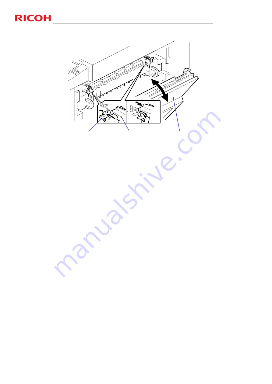
Pressure release lever     Door catch

Right door

Pressure Release

Pressure Release

ˆ

When the right door opens (on each side) it pulls open the door catch (on each 
side). This releases pressure on the pressure roller, allowing the pressure roller 
to turn freely, assisting in removal of jams. 

ˆ

When the right door closes, the pressure release lever pushes the door catch 
closed. This lets normal pressure return.

Содержание D109

Страница 1: ...S C4L Training 1 Slide 1 D109 D110 Service Training Product Outline No additional notes ...

Страница 2: ...S C4L Training 2 Slide 2 Machine Appearance By pass tray and duplex unit Optional paper tray Internal Tray Standard Tray Auto Reverse document Feeder ARDF Option No additional notes ...

Страница 3: ...S C4L Training 3 Slide 3 Operation Panel No additional notes ...

Страница 4: ...matically scans double sided pages optional on this model Color scanning ability added for saving as data in computers via TWAIN Overall performance improvement with faster operation over previous version GDI Controller USB 2 0 Ethernet with NIC option for D109 No additional notes ...

Страница 5: ...ntroller Box D109 USB Motherboard Connection Note that the exact shape of the production controller box may slightly vary from the picture above but the location of the motherboard connection and connectivity jacks should be the same ...

Страница 6: ...Box D110 Ethernet with NIC USB Motherboard Connection Note that the exact shape of the production controller box may slightly vary from the picture above but the location of the motherboard connection and connectivity jacks should be the same ...

Страница 7: ...sonal business machine Mid to large sized offices 10 50 people as a work group division printer scanner Mid to large sized offices as a business personal machine This machine has these benefits Compact size Quick warm up time Standard duplex printing both scan and print Copier printer No additional notes ...

Страница 8: ...e operating instructions general settings section and examine what you can do with this machine As this is only a brief introduction also refer to the operating instructions in the Machine Overview and Machine Operation training module No additional notes ...

Страница 9: ...pecifications In this section you will do these things Examine the general specifications for the machine Examine the machine configuration When you finish this section you should know the answers to these questions What are the main specifications for this machine Are the specifications the same for all models ...

Страница 10: ...canning electrophotographic printing Copy speed 17 ppm A4 8 x 11 100 Warm up basic 10 seconds or less First copy time 7 5 seconds or less Copy paper capacity Paper tray 250 sheets Optional paper tray 500 sheets x 2 Bypass 100 sheets Toner Yield 7 000 copies per toner bottle No additional notes ...

Страница 11: ...n of the machine s specifications refer to the Specifications section of the Field Service Manual noting in particular the following Copy paper size Copy paper weight Power consumption and machine dimensions Copy paper capacity Original paper size Paper feed No additional notes ...

Страница 12: ... There are two machines in this series D109 for Asia GDI controller without NIC NIC is an option D110 for Europe GDI controller with NIC Standard 250 Copy Duplex 250 sheet x1 tray 100 sheet bypass tray 250 sheet output tray GDI printer USB 2 0 Color Scan Options 500 ARDF 500 Sheet Tray Accessibility handle No additional notes ...

Страница 13: ... In this section you will do these things Install the main machine When you finish this section you should know the answers to these questions How do I install this machine What do I have to do after I have installed the machine Is there any firmware for this machine ...

Страница 14: ...ment ventilation temperature range etc Space and power requirements Accessory check for the model you will install Before installing optional units be sure to Switch the machine off and remove the power cord and network cable Keep the system parameter report You will need it for any future troubleshooting of the machine No additional notes ...

Страница 15: ...mind the following when you install the machine and paper tray unit You do not need to pull the toner bottle holder all the way out of the machine Do not remove the inner cap of the toner bottle Do not use force to turn the toner bottle after you have set it in the toner bottle holder The machine will turn the bottle Remove all tape from the machine No additional notes ...

Страница 16: ... machine SP Mode Service Program mode SSP Mode Special Service Program mode Read the Service Program section of the Service Manual Then try entering some of the SP and SSP modes detailed in Unit 5 after you have finished installed the machine Service Program Mode SP SSP modes are for the service technician only Do not let users access SP SSP modes ...

Страница 17: ...e Training Machine Overview and Machine Operation Machine Overview Introducing the machine In this section you will do these things Examine mechanical and electrical components Examine the paper path and drive layout Learn the basic copy process ...

Страница 18: ...ion Pad 29 Paper Feed Roller 30 Paper End Sensor 31 TD Toner Density Sensor 32 Bottom Plate 33 Polygon Mirror Motor 34 Laser Unit 35 Toner Supply Bottle or THM 36 Toner Collection Coil 37 Scanner HP Sensor 1 Exposure Lamp 2 1st Scanner 3 CCD on SBU 4 Lens Block 5 2nd Scanner 6 2nd Mirror 7 3rd Mirror 8 Platen Cover Sensor 9 Exposure Glass 10 Exit Roller 11 Exit Sensor 12 Scanner Motor 13 Hot Rolle...

Страница 19: ...Density Sensor 12 Registration Sensor 13 Paper End Sensor 14 Toner Density Sensor 15 Bypass Paper End Sensor 16 Right Door Safety Switch 17 Front Door Safety Switch 18 Quenching Lamp 1 Lens Block 2 Exposure Lamp 3 Lamp Stabilizer Board 4 Scanner HP Sensor 5 Platen Cover Sensor 6 Scanner Motor 7 Mechanical Counter 8 Polygon Mirror Motor 9 LD Unit ...

Страница 20: ...mponents 2 The callout key is in the notes Component names 1 Duplex Motor 2 Exhaust Fan 3 PSU 4 Controller Board GDI 5 BICU 6 Main Motor 7 Paper Feed Clutch 8 Toner Supply Clutch 9 Bypass Feed Clutch 10 Registration Clutch 11 Fusing Solenoid ...

Страница 21: ...S C4L Training 21 Slide 21 Paper Path Paper Path The paper path is indicated on the slide with heavy black lines and arrows The ARDF is optional ...

Страница 22: ...e 22 Drive Layout Toner Bottle Clutch Main Motor Paper Feed Clutch Scanner Motor Duplex Motor Exit Roller Drive Layout The slide shows some of the drive components For more details and information refer to the Service Manual ...

Страница 23: ...n Motor Toner Supply Clutch Quenching Lamp Exposure Lamp Lamp Stabilizer PCU Paper Feed Clutch Fusing Solenoid HVP Board Registration Clutch Bypass Feed Clutch Sensors LD Unit Operation Panel Fusing Lamp PSU Tray Heater Document Feeder Mechanical Counter Paper Tray Unit BICU No additional notes ...

Страница 24: ...you have There are two different procedures SP5 824 1 NVRAM Upload From the BICU to a flash memory card SP5 825 1 NVRAM Download From a flash memory card to the BICU Practice as outlined in the NVRAM Data Upload Download SP5 824 825 section of the Service Tables unit No additional notes ...

Страница 25: ...fter clearing engine data SP 5801 2 If you replace any of these First scanner or second scanner lens block scanner motor polygon mirror motor paper tray Do adjustments as outlined in Adjusting Copy Image Area section of Replacement and Adjustment chapter of Service Manual No additional notes ...

Страница 26: ...Instructions While these are user operations service technicians should also be generally familiar with them Read these if you re not already familiar with them User Tools General settings Placing originals and copying No additional notes ...

Страница 27: ...raining Scanning and Image Processing Scanning and Image Processing Scanning and Image Processing will be covered In this section you will do these things Examine how the machine does image processing Examine the steps involved in image processing ...

Страница 28: ...or Scanning Overview The HP sensor makes sure the scanner is at home position To copy the original is illuminated by the xenon exposure lamp Then the 1st 2nd and 3rd mirrors move reflected light to the lens block Then the lens transmits it to the CCD The 1st scanner has a reflector This helps to not let shadows get on pasted originals ...

Страница 29: ...ive timing belts that drive the 1st scanner The first scanner is attached to timing belts which drive the 2nd scanner with the 2nd scanner s pulleys When you scan in book mode the 2nd scanner moves at half the speed of the 1st scanner Scanner speed is faster for reduction printing and slower for enlargement printing You can adjust magnification in the sub scan direction with SP 4008 This will adju...

Страница 30: ... the AFE on the BICU In the BICU IPU Auto shading filtering magnification scanner gamma correction ID gamma correction VCU Printer gamma correction LD print timing control and laser power PWM control FCI inside the VCU Smoothing The data then moves to the LD drive board in accordance with timing controlled by the BICU CALDA CCD drive AFE drive Data conversion Offset correction AFE Analog digital c...

Страница 31: ...not switch modes at these times When accessing user tools When scanning an original Practice switching modes and getting multi access Refer to Operating Instructions General Settings Guide To learn more about image processing see the Core Technology Manual No additional notes ...

Страница 32: ... In this section you will do these things Examine the laser and PCU units Examine drum drive and drum charge When you finish this section you should know the answers to these questions How do I replace the laser unit What SP modes do I need to use after I replace the laser unit How does the machine detect a new PCU How does the machine clean the charge roller ...

Страница 33: ...ns Laser Unit Overview This machine uses a standard exposure unit The LD unit controls laser output and synchronization The machine cuts the power to the LD drive board when the front door or right door is opened The LD shutter blocks the laser beam path if the toner bottle holder is unlatched ...

Страница 34: ...are installed at the front and right doors The machine will cut power to the LD drive board if either door is opened The corresponding switch cuts the power supply 5VS to the laser diode The safety switches are installed on the 24V line coming from the power supply unit PSU The 24V supply must pass through these switches before converting into the 5VS power that drives the laser ...

Страница 35: ...il OPC drum Development roller Mixing auger 2 Photoconductor Unit PCU Overview Cleaning roller Charge roller Doctor blade Mixing auger 1 TD sensor PCU Overview Go to the machine and find the above components if you re not already familiar with them ...

Страница 36: ...S C4L Training 36 Slide 36 Drum Drive Drum Drum drive shaft Main motor Drum Drive The main motor drives the drum through a series of gears and the drum drive shaft ...

Страница 37: ...PC drum is charged via a contact charge roller The drum charge roller stays in contact with the drum This gives a charge of 900 V on the drum surface The high voltage supply board gives a negative charge to the charge roller with a wire and spring The default base charge is 1650V You can adjust this with SP 2001 1 ...

Страница 38: ...n initial warm up If the machine is set to low power or auto off mode for more than 4 hours a check will be done when the machine wakes up Procedure Right after the machine creates the ID sensor pattern for toner density control the development bias pattern is created The development bias is decreased to 400 V The ID sensor measures the development bias pattern s density Vsdp and the bare drum s v...

Страница 39: ...S C4L Training 39 Slide 39 Charge Roller Cleaning Cleaning roller Charge Roller Cleaning A cleaning roller cleans the charge roller You do not need to replace or clean this roller ...

Страница 40: ...x Initialize the TD sensor Initialize the PCU counter The machine automatically detects a new PCU and performs initialization In the shipped state the connection plates are pressed together and make a complete circuit This tells the CPU that the PCU is new and must be initialized When the PCU gear rotates the top connection plate gets free and breaks the circuit Pre installed PCUs do not use this ...

Страница 41: ...l do these things Examine toner supply and toner path Examine the toner bottle Examine toner density control Examine SP modes used for the development unit When you finish this section you should know the answers to these questions How is toner supplied to the machine How can I adjust toner density What toner errors does the machine show ...

Страница 42: ...lopment roller Mixing auger 2 Mixing Auger 1 TD sensor Development Overview Two mixing augers mix the developer carrier toner mix The TD toner density sensor and the ID image density sensor shown in a red circle are used to control the copy image density ...

Страница 43: ...with the smallest negative charge The drum has a large negative charge 900V The latent image on the drum has a small negative charge 140 50V The high voltage supply board gives a 600 V bias to the development roller This sends toner from the development roller to the latent image You can adjust the development bias with SP 2201 1 ...

Страница 44: ...a toner bottle is set in the machine The toner bottle cap is held with a chuck The cap comes off when you push in the lever Spiral grooves move toner out of the bottle Mylar blades circled in red move toner through a slit into the development unit This happens when the clutch turns the toner bottle The toner collection coil recycles toner it gets from the OPC drum Recycled toner moves down the chu...

Страница 45: ...ever Shutter Toner Bottle The toner bottle is the same for all models The toner shutter opens when you set the toner bottle into the machine The bottle cap will open when you press the lever Spiral grooves move toner out when the bottle spins ...

Страница 46: ...nitial Setting The Vts for this machine is 1 25 V The machine adjusts the sensor so that it reads out 1 25V for TD sensor initialization when a new PCU is installed Toner Concentration Measurement The machine checks concentration every copy cycle comparing Vt against the reference voltage to do this Vsp Vsg Detection An ID sensor pattern is made on the drum by the charge roller and laser diode The...

Страница 47: ...2 5 when Vsg is read Vsg 3 5 at maximum power Vsp 2 5 Vt 2 64 or Vt 0 20 You can see the current readings with SP 2221 TD Sensor TD 0 20 V TD 2 64 V If the machine gets error readings 10 times in succession SC 390 will be shown You can see the current value with SP 2220 No additional notes ...

Страница 48: ... 85 five times in succession The machine will show toner end at these times VT is Level 6 or VT 1 85 n times in a row VT is at Level 7 or VT 2 00 three times in a row Toner Near End End Detection n is the number of sheets that can be printed before toner near end gets to toner end n is set to 50 by default You can change the value of n to 20 with SP 2213 ...

Страница 49: ...The cleaning blade gets leftover toner from the drum after an image transfer Then toner piles on the blade The toner collect coil moves toner from the pile and puts it onto the chute Then the toner moves to the development unit through a slit The drum turns about 3 mm in reverse at the end of each copy job This moves toner away from the cleaning blade ...

Страница 50: ...e 50 SP Modes SP 2214 Developer initialization SP 2802 Forced developer churning SP 2908 Forced toner supply SP 2921 Toner supply mode SP 2922 Toner supply time SP 2926 Standard Vt SP 2928 Toner end clear No additional notes ...

Страница 51: ...oner Supply Clutch See the procedure in the FSM Preventive Maintenance You must clean the toner bottle holder after you replace the PCU To learn more see the following in the Core Technology Manual Development process Development bias Toner supply No additional notes ...

Страница 52: ...overed In this section you will do these things Examine the paper feed mechanism Examine the paper feed path and drive When you finish this section you should know the answers to these questions How is paper fed through the machine What parts do I need to replace What adjustments do I need to make ...

Страница 53: ...ng 53 Slide 53 Paper Feed Overview Exit roller Paper feed roller Exit sensor By pass feed roller Registration sensor By pass paper end sensor Friction pads Paper end sensor Registration rollers No additional notes ...

Страница 54: ...ion roller Main motor Paper feed roller Registration clutch Paper feed clutch Drive Mechanism From Paper Tray The main motor drives gears on the registration clutch and the paper feed clutch These clutches transmit motion to the registration roller and paper feed roller ...

Страница 55: ... Bypass Tray Bypass feed roller Main motor Registration clutch Bypass feed clutch Drive Mechanism Bypass Tray The main motor drives the gears of the registration clutch and bypass feed clutch The bypass feed clutch moves the bypass feed roller ...

Страница 56: ...S C4L Training 56 Slide 56 Paper Feed And Separation ...

Страница 57: ...pring Projection B Latch Rounded slider Paper Lift Mechanism The projection B on the frame pushes the rounded slider in against the spring when the tray is closed by sliding it into the machine This retracts the latch allowing the bottom plate spring to push the plate up ...

Страница 58: ...S C4L Training 58 Slide 58 Paper End Detection Main Tray Paper end sensor Paper End Detection Main Tray The feeler goes into the cutout when paper runs out Then the paper end sensor is activated ...

Страница 59: ...S C4L Training 59 Slide 59 Paper End Detection Bypass Tray Paper end sensor Feeler Paper End Detection Bypass Tray The feeler goes into the cutout when paper runs out activating the paper end sensor ...

Страница 60: ...S C4L Training 60 Slide 60 Paper Registration Registration sensor No additional notes ...

Страница 61: ...S C4L Training 61 Slide 61 Learn More Refer to the Core Technology Manual Paper path Paper feed process Paper registration Paper transport No additional notes ...

Страница 62: ...paration Image transfer and paper separation will be covered In this section you will do these things Examine how paper is fed through the machine Examine transfer current When you finish this section you should know the answers to these questions How is paper fed through the machine How is the transfer roller cleaned ...

Страница 63: ... against the OPC drum The high power supply board gives a positive charge to the transfer roller which causes toner to be transferred from the drum to the paper This machine uses the following two paper separation techniques The drum s curvature helps separate the paper The discharge plate removes the paper s charge ...

Страница 64: ...fer roller at the time of image transfer This allows the transfer roller to move toner to the paper The high voltage supply board does not supply current when the trailing edge of the paper has passed the transfer roller The high voltage supply board supplies low level current if the machine prints more pages Transfer Current Timing You can adjust the transfer current level with SP 2301 Examine th...

Страница 65: ...pply unit gives a negative charge to the transfer roller Toner with negative charge moves back to the drum Then the high voltage unit provides a positive current Toner with a positive charge moves back to the drum The roller is cleaned at these times When power is switched on After you clear a paper jam At the end of a job if at least 10 print jobs have been made since the last clean cycle You can...

Страница 66: ...positively charged toner came from as the toner gets a negative charge in the development unit Almost all of the toner on the transfer roller is negative 98 However stress and pressure applied to toner particles for example at the cleaning blade or at times of recycle can cause a very small percent to take on a slight positive charge No additional notes ...

Страница 67: ...se things Examine the machine s fusing unit Examine the energy saver mode Examine replacement and adjustments Learn the SP modes used When you finish this section you should know the answers to these questions How many energy saver levels does the machine have What is the target fusing temperature for this machine Which parts in the fusing unit are replaceable ...

Страница 68: ... 68 Slide 68 Pressure spring Pressure roller Exit roller Paper path sensor Fusing lamp Hot roller Overview Overview This slide shows some of the components for the fusing unit For more details see the Service Manual ...

Страница 69: ...in the gear train Drive power of the main motor is not transmitted to the hot roller Drive power of the main motor is not transmitted to the paper exit roller This roller is driven by the exit motor Contact Release Control The contact release solenoid comes on at these times When the copier warms the hot roller When the hot roller temperature is 18 C or higher Fusing idling SP 1103 1 is set to No ...

Страница 70: ...ler The pressure springs constantly press the pressure roller against the hot roller The springs can be set in two different positions The default is set in the high pressure lower position position You can move the springs to the low pressure upper position position if you want to lower the pressure ...

Страница 71: ... the right door opens on each side it pulls open the door catch on each side This releases pressure on the pressure roller allowing the pressure roller to turn freely assisting in removal of jams When the right door closes the pressure release lever pushes the door catch closed This lets normal pressure return ...

Страница 72: ...S C4L Training 72 Slide 72 Separation Separation The hot roller stripper pawls 3 stripper pawls prevent paper from staying on the hot roller ...

Страница 73: ...al from the thermistor every 1 5 seconds The BICU controls the fusing lamp depending on the following conditions Current temperature Previous temperature 1 5 seconds before Target fusing temperature The target fusing temperature starts at 180ºC and then goes to 170ºC after one minute Examine the target temperature table in the Service Manual ...

Страница 74: ...trol Unit stops the machine when the thermistor detects an abnormal condition Then the machine will show one of these SC codes SC 543 SC 544 SC 545 SC 546 Feature 3 The BICU stops the machine if the thermistor does not work correctly Then the copier shows SC 541 Feature 4 The thermostat near the center cuts power to the fusing lamp at 160ºC The thermoswitch near the end cuts power to the fusing la...

Страница 75: ...s the energy saver when in low power mode Timers are user settable The energy saver timer and the auto off timer start at the same time when the machine ends all jobs or when the user ends all manual operations The auto off timer does not wait for the energy saver timer If the user sets a smaller value in the energy saver timer the auto off timer will finish before the energy saver timer Low power...

Страница 76: ...ervice Manual Fusing unit Exit sensor Hot roller stripper pawls Hot roller and fusing lamp Thermoswitch and thermistor Pressure roller Nip band adjustment Contact release solenoid Replacement and Adjustments All parts for the fusing unit have the same PM intervals You must replace or clean these components at PM 90 K ...

Страница 77: ...S C4L Training 77 Slide 77 Learn More Core Technology Manual Fusing overview Stripper Pawls No additional notes ...

Страница 78: ...n you will do these things Examine the duplex print procedure Examine the adjustments for the duplex unit Learn the SP modes used in the duplex unit When you finish this section you should know the answers to these questions How is duplex printing done with this machine What do I need to replace or adjust in the duplex unit ...

Страница 79: ...th sensor Fusing unit Duplex roller Exit rollers Mechanical Layout The exit motor drives the exit roller and duplex roller One of the paper guides on the fusing unit is linked to the duplex timing sensor The bypass tray cannot be used for duplex printing ...

Страница 80: ...ain motor and duplex motor 2 The hot roller A and pressure roller B transport the paper to the paper guide C 3 The leading edge of the paper pushes the paper guide the paper guide turns the paper path sensor D on 4 When the leading edge of the paper reaches the exit roller E the exit roller transports the paper Continued on next slide No additional notes ...

Страница 81: ...ion F and turns the paper path sensor G off 6 The controller starts to operate the duplex motor in reverse the exit roller H turns in reverse transporting the paper to the duplex roller 7 The paper goes over the paper guide and reaches the duplex roller I 8 The duplex roller transports the paper into the duplex unit The paper goes through the unit Continued on next slide No additional notes ...

Страница 82: ...otor The duplex roller holds the paper in the duplex unit 10 When the OPC drum K gets ready for printing the controller restarts the duplex motor The duplex roller transports the paper 11 The duplex roller keeps transporting the paper until the paper reaches the fusing unit 12 The hot and pressure rollers transport the paper to the paper guide Continued on next slide No additional notes ...

Страница 83: ... 13 The leading edge of the paper pushes the paper guide L the paper guide turns the paper path sensor M on 14 The controller changes the direction of the duplex motor The exit roller N changes the direction of its rotation transporting the paper to the copy tray No additional notes ...

Страница 84: ...des in the Service Manual SP 1001 3 Leading edge registration SP 1002 6 Side to side registration SP 1003 5 Paper feed timing SP 2301 3 Transfer current timing SP 7504 60 Off registration duplex SP 7504 123 Off duplex inverter SP 7504 125 On duplex inverter No additional notes ...

Страница 85: ...S C4L Training 85 Slide 85 Learn More Core Technology Manual Duplex printing Interleave duplexing No additional notes ...

Страница 86: ...ssed In this section you will do these things Examine the mechanical layout for the ARDF Examine the feed process Review the replacement and adjustment procedures When you finish this section you should know the answers to these questions Are the optics fixed or do they move for original scanning What paper sizes can the ARDF handle ...

Страница 87: ...er weight 52 105 g m 14 28 lb Tray Capacity 50 sheets 80 g m 21 lb Transport Roller transport Feed order Top first Separation FRR Feed and Reverse Roller Original transport Roller transport Reproduction range 50 200 Power source 24 and 5 Vdc from the copier Specifications The ARDF is optional ...

Страница 88: ...t Separation Roller Paper Feed Roller Pick up Roller Exit Roller Junction Gate Inverter Roller Mechanical Layout This slide shows some of the components for the ARDF See the ARDF DF1000 B872 Service Manual for full details and technical drawings ...

Страница 89: ...S C4L Training 89 Slide 89 Electrical Component Layout 1 Registration Sensor Left Cover Sensor Inverter Sensor DF Drive Board Original Set Sensor Junction Gate Solenoid No additional notes ...

Страница 90: ...S C4L Training 90 Slide 90 Electrical Component Layout 2 DF Drive Board No additional notes ...

Страница 91: ...S C4L Training 91 Slide 91 Electrical Component Layout 3 DF Drive Board No additional notes ...

Страница 92: ... Layout DF Feed Motor Feed Roller Registration Roller Exit Roller Transport Roller DF Feed Clutch Drive Layout This slide shows the major components Refer to the ARDF DF1000 B872 Service Manual for full details and technical drawings ...

Страница 93: ...Feed Roller Original set sensor Original Size Detection The original pushes down the feeler of the original set sensor when you put an original on the feeder table The copier exits energy saver mode if energy saver mode is enabled The ARDF does not detect paper sizes ...

Страница 94: ...top sheet s between the feed and separation roller where the top sheet is separated and fed to the transport rollers Clutch Operation The DF feed clutch stops feeding when the original is fed to the inverter tray in double sided mode If the DF feed clutch didn t stop pick up feed and separation rollers in double sided mode the next original would be fed while the first original was at the inverter...

Страница 95: ...f original passes the exit sensor the junction gate solenoid switches off and the junction gate is closed Following feeding of the original onto the inverter table feed and transport motors stop The feed motor rotates in reverse and the original is fed to the exit roller by the inverter roller Feed motor stops briefly to adjust original skew After adjusting original is fed again by exit roller and...

Страница 96: ...S C4L Training 96 Slide 96 Paper Transport Two sided Originals 1 No additional notes ...

Страница 97: ...S C4L Training 97 Slide 97 Paper Transport Two sided Originals 2 No additional notes ...

Страница 98: ...S C4L Training 98 Slide 98 Paper Transport Two sided Originals 3 No additional notes ...

Страница 99: ...and original table See Replacement and Adjustment section of ARDF DF1000 B872 Service Manual Practice the removal procedures for the following as outlined in the Service Manual Pick up roller Paper feed roller Separation roller DF feed motor DF feed clutch Sensors DF drive board No additional notes ...

Страница 100: ...ling erase SP 6006 5 Sub scan magnification SP 6009 1 ARDF free run in duplex mode SP 6009 3 ARDF free run in simplex mode SP 6910 1 ARDF shading time These SC codes are for the ARDF They are all level B error codes SC 760 DF gate error 1 SC 761 DF gate abnormal 2 SC 762 DF gate abnormal 3 Practice using the above SP modes if you are unfamiliar with them No additional notes ...

Страница 101: ...S C4L Training 101 Slide 101 Preventive Maintenance These need to be replaced at PM interval 90K Separation roller Pick up roller Feed roller Clean the remaining parts when necessary No additional notes ...

Страница 102: ...e things Examine the mechanical layout for the paper tray unit Examine drive and paper lift Learn how the paper tray unit detects the paper end Replace the friction pad and feed roller When you finish this section you should know the answers to these questions What feed mechanism does the paper tray unit use How is the paper end detected Which components will I need to replace ...

Страница 103: ...anisms for these Paper feed friction pad method Paper lift springs Paper end detection feeler method The paper tray unit does not have any mechanism to detect paper size If you want to change the paper size you must set the new paper size in the machine memory with a user tool This will prevent timing jams No additional notes ...

Страница 104: ...ining 104 Slide 104 Specifications Paper sizes A4 SEF 8 x 11 SEF 8 x 13 SEF 8 x 14 SEF Paper weight 60 90 g m 16 24 lb Tray Capacity 500 sheets Paper feed system Feed roller and friction pad No additional notes ...

Страница 105: ...ng 105 Slide 105 Mechanical Component Layout Optional tray heater Feed roller Bottom plate Friction pad Refer to the B421 Paper Tray Unit Service Manual full electrical component layout details No additional notes ...

Страница 106: ...S C4L Training 106 Slide 106 Drive Layout Paper feed motor Feed roller Paper feed clutch Friction pad Drive Layout Find these components if you re not already familiar with them ...

Страница 107: ...S C4L Training 107 Slide 107 Paper Feed and Separation Paper feed roller Friction pad Paper Feed and Separation Find these components if you re not already familiar with them ...

Страница 108: ...ate the latch will set locking the plate down compressing the spring below After loading in paper when you push the paper tray back into the machine the runner pushes the rounded slider releasing the latch Then the compressed springs push the plate up and keep the latch retracted preventing the plate from becoming locked down under a full load of paper ...

Страница 109: ... End Detection If there is some paper in the tray the feeler will push up and sense this If there is no paper in the tray the feeler drops in the cutout and activates the sensor The feeler is rounded and moves when the tray is pushed in or out preventing the feeler from getting caught in the tray ...

Страница 110: ... and End Fences Side Fence Set width to A4 81 4 or 81 2 End fence Set from 11 to 13 with standard settings at 11 A4 and 13 To feed 14 paper the end fence must be removed and stored in an internal storage compartment You can secure both fences with screws at standard positions ...

Страница 111: ...cedures Read Paper Tray Unit section of Service Manual You will usually have to replace these PM interval every 120K in the field due to normal wear and tear Practice these removal procedures Feed roller and friction pad Sensors Drive block Paper feed motor Paper feed clutch Tray main board Clean the bottom plate when necessary No additional notes ...

Страница 112: ...lide 112 D109 D110 Service Training Preventive Maintenance Preventive Maintenance PM intervals for the machine will be covered In this section you will do these things Examine the PM table Learn how to clear the PM counter ...

Страница 113: ...st parts have a PM interval of 90 K the PCU has a PM interval of 45 K Some parts require cleaning only You do not need to replace these parts You must clear the PM counter with SP 7804 after you do a PM schedule Read these Preventative Maintenance chapter of the Service Manual How to clear the PM counter SP 7804 1 No additional notes ...

Страница 114: ...y Image Adjustments Overview You need to do copy image adjustments if you do these Do a memory all clear Replace the first or second scanner Replace the lens block Replace the polygon mirror Replace the paper tray No additional notes ...

Страница 115: ...d make sure the registration is set to the correct tolerance levels Blank margin Adjust the leading edge and left edge margins only if you could not correctly adjust the registration Printing Adjustments Make sure the paper is set correctly in the paper tray before starting Use SP 5902 to print the test pattern to check the adjustments Blank margin Adjust the margins in this order Trailing edge Ri...

Страница 116: ... for this adjustment Main scan magnification Use SP 4009 for this adjustment Scan Auto Adjustment See Scan Auto Adjustment in the Preventive Maintenance chapter of the Service Manual Scanning Adjustments Do the registration and blank margin adjustments for printing before you adjust the scanner Use the A4 test chart to perform all adjustments ...

Страница 117: ...ction you will do these things Examine the error codes and SC code tables Examine sensor and switch errors Check machine functions When you finish this section you should know the answers to these questions How do I troubleshoot this machine What machine checks can I do in the field ...

Страница 118: ...eared by the user and which codes cannot be cleared by the user FSM Æ Troubleshooting Æ Service Call Conditions Study the SC code table FSM Æ Appendix Troubleshooting Æ SC Code Table Overview Examine these before you replace any component in the machine If the problem is with circuit boards Disconnect and then reconnect all connectors before you replace a circuit board If the problem is with a mot...

Страница 119: ...ble explains symptoms the machine will exhibit when a sensor or switched circuit is in an open condition Open the front or right door Make sure the Close Front Right Cover message is indicated on the screen Do some of the open sensor examples Make sure you do not damage the connectors No additional notes ...

Страница 120: ...itions Read the Blow Fuse Conditions section of the Troubleshooting unit of the Service Manual It shows what happens if one of the fuses blows on the power supply board Pull the copy tray out to simulate a blown fuse condition No additional notes ...

Страница 121: ...terns Print several of the test patterns indicated in the Test Pattern Print SP 5902 1 section of the Service Tables unit in the Service Manual Output check Use the output check mode to test the operation of the polygon motor main motor and fan motor Free run Scanner SP 4013 Machine SP 5802 Printer SP 5901 ARDF SP 6009 No additional notes ...

Страница 122: ... check This lets you check the condition of most sensors and switches in the machine ID sensor analysis SP 2221 lets you check these Vsg displayed as Vg Vsp displayed as Vp Power displayed as PW This is the power for the light source Vsdp displayed as Vg Vp This value does not have any error conditions Vt No additional notes ...

Отзывы: